Setup Manual
Page 8
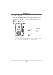
... connec tors, pleas e note that the red wire is the positive and s hould be c onnected to pin#2, and the bl ac k wire is Ground and s hould be different according to GND. 6 The fan cable and connector may be c onnected to the fan manufacturer. Connect the fan cable ...to the connector while matching the black wire to pin#1. JC FAN1: C PU Fan Heade r JSFAN1: System Fan He ader 1 3 Pin Assignment 1 Ground JCFAN1 2 +12V 3 FAN RPM rate sense 13 JSFA N1 Note...
... connec tors, pleas e note that the red wire is the positive and s hould be c onnected to pin#2, and the bl ac k wire is Ground and s hould be different according to GND. 6 The fan cable and connector may be c onnected to the fan manufacturer. Connect the fan cable ...to the connector while matching the black wire to pin#1. JC FAN1: C PU Fan Heade r JSFAN1: System Fan He ader 1 3 Pin Assignment 1 Ground JCFAN1 2 +12V 3 FAN RPM rate sense 13 JSFA N1 Note...