
Setup Manual
Page 1
... reserves the right to revise this publication, in part or in whole, is subject to be c hanged without first obtaining the vendor's approval in writing. K8M800 Micro AM2 Setup Manual FCC Information and Copyright This equipment has been tes ted and found in accordance with respec t to the contents here and s pecially disclaims...
... reserves the right to revise this publication, in part or in whole, is subject to be c hanged without first obtaining the vendor's approval in writing. K8M800 Micro AM2 Setup Manual FCC Information and Copyright This equipment has been tes ted and found in accordance with respec t to the contents here and s pecially disclaims...
Setup Manual
Page 2
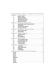
Table of Contents Chapter 1: Introduction 1 1.1 Before You Start 1 1.2 Package Checklist 1 1.3 Motherboard Features 2 1.4 Rear Panel Connectors 3 1.5 Motherboard Layout 4 Chapter 2: Hardware Installation 5 2.1 Installing Central Processing Unit (CPU 5 2.2 FAN Headers 7 2.3 Installing System Memory 8 2.4 Connectors and Slots 10 Chapter 3: Headers & Jumpers Setup 12 3.1 How to Setup Jumpers 12 3.2 Detail Settings 12 Chapter 4: RAID Functions 17 4.1 Operation System 17 4.2 Raid Arrays 17 4.3 How RAID Works 17 Chapter 5: Useful Help 19 5.1 ...
Table of Contents Chapter 1: Introduction 1 1.1 Before You Start 1 1.2 Package Checklist 1 1.3 Motherboard Features 2 1.4 Rear Panel Connectors 3 1.5 Motherboard Layout 4 Chapter 2: Hardware Installation 5 2.1 Installing Central Processing Unit (CPU 5 2.2 FAN Headers 7 2.3 Installing System Memory 8 2.4 Connectors and Slots 10 Chapter 3: Headers & Jumpers Setup 12 3.1 How to Setup Jumpers 12 3.2 Detail Settings 12 Chapter 4: RAID Functions 17 4.1 Operation System 17 4.2 Raid Arrays 17 4.3 How RAID Works 17 Chapter 5: Useful Help 19 5.1 ...

Setup Manual
Page 3
... equipment. „ Keep the compute r from anti-static bag, ground yourse lf prope rly by touching any unfastene d small parts inside the case afte r installation. K8M800 Micro A M2 CHAPTER 1: INTRODUCTION 1.1 BEFORE YOU START Thank you for ATX Case X 1 Se rial ATA Cable X 1 (optional) USB 2.0 Cable X1 (optional) S/PDIF Cable X 1 (optional) Se rial...
... equipment. „ Keep the compute r from anti-static bag, ground yourse lf prope rly by touching any unfastene d small parts inside the case afte r installation. K8M800 Micro A M2 CHAPTER 1: INTRODUCTION 1.1 BEFORE YOU START Thank you for ATX Case X 1 Se rial ATA Cable X 1 (optional) USB 2.0 Cable X1 (optional) S/PDIF Cable X 1 (optional) Se rial...

Setup Manual
Page 4
... Bandwidth Environment Control initiatives, Super I/O Provides the most commonly usedlegacy H/W Monitor Super I/O functionality. SATA Version 1.0specificationcompliant. Motherboard Manual 1.3 MOT HERBOARD FEAT URES SPEC CPU Socket AM2 AMDSempron processors Supports Hyper Transport andCool=n=Quiet FSB Chipset Support HyperTransport K8M80 0 VT823 7R+ ITE IT8705 Supports up to 1.5 Gb/s.
... Bandwidth Environment Control initiatives, Super I/O Provides the most commonly usedlegacy H/W Monitor Super I/O functionality. SATA Version 1.0specificationcompliant. Motherboard Manual 1.3 MOT HERBOARD FEAT URES SPEC CPU Socket AM2 AMDSempron processors Supports Hyper Transport andCool=n=Quiet FSB Chipset Support HyperTransport K8M80 0 VT823 7R+ ITE IT8705 Supports up to 1.5 Gb/s.

Setup Manual
Page 5
... Printer Port I/O VGA port LAN port USB Port Audio Jack BoardSize 197 x 243 (mm) Special Features RAID 0 / 1 support OS Support Windows 2000 / XP K8M800 Micro A M2 SPEC x1 Connects to Power supply x1 Connects to Power supply x1 Connects to PS/2 Keyboard x1 Connects to PS/2 Mouse x1 Connects to...Connects to D-SUB Screen x1 Connects to RJ-45 ethernet cable x4 Connects to USB devices x3 Provide Audio-In/Out and microphone connection Micro ATX Size Board Biostar Reserves the right to add or remove support for any OS Withor without notice. 1.4 REAR PANEL CONNECT ORS PS/2 Mou se Printe ...
... Printer Port I/O VGA port LAN port USB Port Audio Jack BoardSize 197 x 243 (mm) Special Features RAID 0 / 1 support OS Support Windows 2000 / XP K8M800 Micro A M2 SPEC x1 Connects to Power supply x1 Connects to Power supply x1 Connects to PS/2 Keyboard x1 Connects to PS/2 Mouse x1 Connects to...Connects to D-SUB Screen x1 Connects to RJ-45 ethernet cable x4 Connects to USB devices x3 Provide Audio-In/Out and microphone connection Micro ATX Size Board Biostar Reserves the right to add or remove support for any OS Withor without notice. 1.4 REAR PANEL CONNECT ORS PS/2 Mou se Printe ...

Setup Manual
Page 6
Motherboard Manual 1.5 MOT HERBOARD LAYOUT JKB MS1 JATX PWR1 DIMMA1 DIMMB1 F DD1 Socket A M2 JPRNT1 J CO M1 JVGA1 IDE1 IDE2 JUS B1 JUSBLAN1 JATXP WR2 JCFAN1 JAUDIO1 K8M800 Super I/O LAN AGP 1 BIOS PCI1 Codec PCI2 JAUDIO2 JCDIN1 JSPDIF_OUT1 JSFAN1 Not e: ■ repre sents the 1st pin. 4 BAT1 VT8237R+ JCMOS1 JSATA2 JUSB2 JUSB3 JS ATA1 J PA NE L1
Motherboard Manual 1.5 MOT HERBOARD LAYOUT JKB MS1 JATX PWR1 DIMMA1 DIMMB1 F DD1 Socket A M2 JPRNT1 J CO M1 JVGA1 IDE1 IDE2 JUS B1 JUSBLAN1 JATXP WR2 JCFAN1 JAUDIO1 K8M800 Super I/O LAN AGP 1 BIOS PCI1 Codec PCI2 JAUDIO2 JCDIN1 JSPDIF_OUT1 JSFAN1 Not e: ■ repre sents the 1st pin. 4 BAT1 VT8237R+ JCMOS1 JSATA2 JUSB2 JUSB3 JS ATA1 J PA NE L1

Setup Manual
Page 7
The CPU will fit only in the correct orientation. 5 Step 2: Pull the lever toward direction A from the socket and then raise the lever up to a 90-degree angle. Step 3: Look for the white triangle on socket, and the gold triangle on CPU should point towards this white triangle. K8M800 Micro A M2 CHAPTER 2: HARDWARE INSTALLATION 2.1 INST ALLING CENT RAL PROCESSING UNIT (CPU) Step 1: Remove the socket protection cap.
The CPU will fit only in the correct orientation. 5 Step 2: Pull the lever toward direction A from the socket and then raise the lever up to a 90-degree angle. Step 3: Look for the white triangle on socket, and the gold triangle on CPU should point towards this white triangle. K8M800 Micro A M2 CHAPTER 2: HARDWARE INSTALLATION 2.1 INST ALLING CENT RAL PROCESSING UNIT (CPU) Step 1: Remove the socket protection cap.

Setup Manual
Page 8
This completes the installation. 6 Connect the CPU FAN power cable to complete the installation. Step 5: Put the CPU Fan on the CPU and buckle it. Motherboard Manual Step 4: Hold the CPU down firmly, and then close the lever toward direct B to the JCFAN1.
This completes the installation. 6 Connect the CPU FAN power cable to complete the installation. Step 5: Put the CPU Fan on the CPU and buckle it. Motherboard Manual Step 4: Hold the CPU down firmly, and then close the lever toward direct B to the JCFAN1.
Setup Manual
Page 9
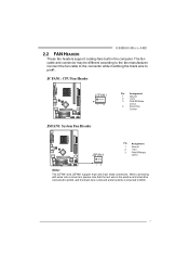
... manufacturer. Connect the fan cable to the connector while matching the black wire to GND. 7 The fan cable and connector may be c onnected to pin#1. K8M800 Micro A M2 2.2 FAN HEADERS These fan headers support cooling-fans built in the computer.
... manufacturer. Connect the fan cable to the connector while matching the black wire to GND. 7 The fan cable and connector may be c onnected to pin#1. K8M800 Micro A M2 2.2 FAN HEADERS These fan headers support cooling-fans built in the computer.

Setup Manual
Page 10
Insert the DIMM vertically and firmly into the slot until the retaining chip snap back in place and the DIMM is properly seated. Align a DIMM on the slot such that the notch on the DIMM matches the break on the Slot. 2. Memory Capacity DIMM Socket Location DIMMA1 DIMMB1 DDR Module 256MB/512MB/1GB *1 256MB/512MB/1GB *1 Total Memory Size Max memory 2GB. 8 DDR2 module DIMMA1 DIMMB1 1. B. Motherboard Manual 2.3 INST ALLING SYST EM MEMORY A. Unlock a DIMM slot by pressing the retaining clips outward.
Insert the DIMM vertically and firmly into the slot until the retaining chip snap back in place and the DIMM is properly seated. Align a DIMM on the slot such that the notch on the DIMM matches the break on the Slot. 2. Memory Capacity DIMM Socket Location DIMMA1 DIMMB1 DDR Module 256MB/512MB/1GB *1 256MB/512MB/1GB *1 Total Memory Size Max memory 2GB. 8 DDR2 module DIMMA1 DIMMB1 1. B. Motherboard Manual 2.3 INST ALLING SYST EM MEMORY A. Unlock a DIMM slot by pressing the retaining clips outward.

Setup Manual
Page 11
K8M800 Micro A M2 C. Dual Channel Status DIMMA1 DIMMB1 Disabled O X Disabled X O Enabled O O (O means memory installed, X means memory not installed.) The DRAM bus width of the memory module must meet the following requirements: Install memory module of the motherboard, the memory module must be the same (x8 or x16) 9 Dual Channel Memory installation To trigger the Dual Channel f unction of the same density in pair, shown in the following table.
K8M800 Micro A M2 C. Dual Channel Status DIMMA1 DIMMB1 Disabled O X Disabled X O Enabled O O (O means memory installed, X means memory not installed.) The DRAM bus width of the memory module must meet the following requirements: Install memory module of the motherboard, the memory module must be the same (x8 or x16) 9 Dual Channel Memory installation To trigger the Dual Channel f unction of the same density in pair, shown in the following table.

Setup Manual
Page 12
Motherboard Manual 2.4 CONNECT ORS AND SLOT S FDD1: Floppy Disk Conne ctor The motherboard prov ides a standard floppy disk connector that prov ides PIO Mode 0~4, Bus Master, and Ultra DMA 33/66/100/133 f unctionality. The f irst hard drive should always be connected to four hard disk drives. The IDE connectors can connect a master and a slav e driv e, so y ou can connect up to IDE1. 40 39 2 1 IDE1 IDE2 10 This connector supports the prov ided f loppy drive ribbon cables. 34 33 2 1 IDE1/IDE2: Hard Disk Conne ctors The motherboard has a 32-bit Enhanced PCI IDE Controller ...
Motherboard Manual 2.4 CONNECT ORS AND SLOT S FDD1: Floppy Disk Conne ctor The motherboard prov ides a standard floppy disk connector that prov ides PIO Mode 0~4, Bus Master, and Ultra DMA 33/66/100/133 f unctionality. The f irst hard drive should always be connected to four hard disk drives. The IDE connectors can connect a master and a slav e driv e, so y ou can connect up to IDE1. 40 39 2 1 IDE1 IDE2 10 This connector supports the prov ided f loppy drive ribbon cables. 34 33 2 1 IDE1/IDE2: Hard Disk Conne ctors The motherboard has a 32-bit Enhanced PCI IDE Controller ...

Setup Manual
Page 13
K8M800 Micro A M2 PCI1~PCI2: Pe riphe ral Component Interconne ct Slots This motherboard is also equipped with an Accelerated Graphics Port (AGP). An AGP card will ...
K8M800 Micro A M2 PCI1~PCI2: Pe riphe ral Component Interconne ct Slots This motherboard is also equipped with an Accelerated Graphics Port (AGP). An AGP card will ...

Setup Manual
Page 14
It allows user to set up jumpers. When the jumper cap is "open". Motherboard Manual CHAPTER 3: HEADERS & JUMPERS SETUP 3.1 HOW T O SET UP JUMPERS The illustration shows how to connect the PC case's f ront panel switch functions. PWR _LED SLP On/Off ++ - 9 16 1 +- 8 SPK RST H LED Pin Assignment 1 +5V 2 N/A 3 N/A 4 Speaker 5 HDD LED (+) 6 HDD LED (-) 7 Ground 8 Reset control Functio n Pin 9 Speaker 10 Connec tor 11 12 Hard drive 13 LED 14 Reset button 15 16 Assignment Sleep control Ground N/A Power LED (+) Power LED (+) Power LED (-) Power button Ground ...
It allows user to set up jumpers. When the jumper cap is "open". Motherboard Manual CHAPTER 3: HEADERS & JUMPERS SETUP 3.1 HOW T O SET UP JUMPERS The illustration shows how to connect the PC case's f ront panel switch functions. PWR _LED SLP On/Off ++ - 9 16 1 +- 8 SPK RST H LED Pin Assignment 1 +5V 2 N/A 3 N/A 4 Speaker 5 HDD LED (+) 6 HDD LED (-) 7 Ground 8 Reset control Functio n Pin 9 Speaker 10 Connec tor 11 12 Hard drive 13 LED 14 Reset button 15 16 Assignment Sleep control Ground N/A Power LED (+) Power LED (+) Power LED (-) Power button Ground ...

Setup Manual
Page 15
K8M800 Micro A M2 JATXPWR1: ATX Powe r Source C onne ctor This connector allows user to CPU power circuit. JATX PWR1 10 20 1 11 Pin Assignment 1 +3.3V 2 +3.3V 3 Ground 4 +...
K8M800 Micro A M2 JATXPWR1: ATX Powe r Source C onne ctor This connector allows user to CPU power circuit. JATX PWR1 10 20 1 11 Pin Assignment 1 +3.3V 2 +3.3V 3 Ground 4 +...

Setup Manual
Page 16
JUSB2 JUSB3 2 10 1 9 Pin Assignment 1 +5V (fused) 2 +5V (fused) 3 USB4 USB5 USB+ 6 USB+ 7 Ground 8 Ground 9 Key 10 NC JAUDIO 2: Front Panel Audio Heade r This header allows user to connect additional USB cable on back panel audio connectors. Pin Assignment 1 Mic in/center 2 Ground 3 Mic power/Bass 4 Audio power 5 Right line out/ Speaker out Right 6 Right line out/ Speaker out Right 7 Res erved 8 Key 9 Left line out/ Speaker out Left 2 14 10 Left line out/ Speaker out Left 11 Right line in/ 1 13 Rear speaker Right 12 Right line in/ Rear speaker ...
JUSB2 JUSB3 2 10 1 9 Pin Assignment 1 +5V (fused) 2 +5V (fused) 3 USB4 USB5 USB+ 6 USB+ 7 Ground 8 Ground 9 Key 10 NC JAUDIO 2: Front Panel Audio Heade r This header allows user to connect additional USB cable on back panel audio connectors. Pin Assignment 1 Mic in/center 2 Ground 3 Mic power/Bass 4 Audio power 5 Right line out/ Speaker out Right 6 Right line out/ Speaker out Right 7 Res erved 8 Key 9 Left line out/ Speaker out Left 2 14 10 Left line out/ Speaker out Left 11 Right line in/ 1 13 Rear speaker Right 12 Right line in/ Rear speaker ...

Setup Manual
Page 17
... 1-2 close ". 3. Reset your desired password or clear the CMOS data. 15 Remov e AC power line. 2. Wait f or f ive seconds. 4. Set the jumper to "Pin 2-3 close ". 5. K8M800 Micro A M2 JCDIN1: CD-RO M Audio-in Connector This connector allows user to connect the audio source f rom the v ariaty dev ices, like CD-ROM, DVD...
... 1-2 close ". 3. Reset your desired password or clear the CMOS data. 15 Remov e AC power line. 2. Wait f or f ive seconds. 4. Set the jumper to "Pin 2-3 close ". 5. K8M800 Micro A M2 JCDIN1: CD-RO M Audio-in Connector This connector allows user to connect the audio source f rom the v ariaty dev ices, like CD-ROM, DVD...

Setup Manual
Page 18
Motherboard Manual JSATA1~JSATA2: Se rial ATA C onne ctors The motherboard has a PCI to connect the PCI bracket SPDIF output header. 13 Pin Assignment 1 +5V 2 SPDIF_OUT 1 3 Ground 16 JSATA1 JSATA2 741 Pin Assignment 1 Ground 2 TX+ 3 TX4 Ground 5 RX6 RX+ 7 Ground JSPDIF_O UT1: Digital Audio out Conne ctors This connector allows user to SATA Controller with 2 channels SATA interface, it satisfies the SATA 1.0 spec and with transfer rate of 1.5Gb/s.
Motherboard Manual JSATA1~JSATA2: Se rial ATA C onne ctors The motherboard has a PCI to connect the PCI bracket SPDIF output header. 13 Pin Assignment 1 +5V 2 SPDIF_OUT 1 3 Ground 16 JSATA1 JSATA2 741 Pin Assignment 1 Ground 2 TX+ 3 TX4 Ground 5 RX6 RX+ 7 Ground JSPDIF_O UT1: Digital Audio out Conne ctors This connector allows user to SATA Controller with 2 channels SATA interface, it satisfies the SATA 1.0 spec and with transfer rate of 1.5Gb/s.

Setup Manual
Page 19
.... No capacity loss penalty f or parity. Drawbacks: Does not deliver any drive in a RAID 0 array system. Depending on the system environment. CHAPTER 4: RAID FUNCTIONS K8M800 Micro A M2 4.1 OPERAT ION SYST EM Supports Windows XP Home/Prof essional Edition, and Windows 2000 Professional. 4.2 RAID ARRAYS RAID supports the following types of RAID...
.... No capacity loss penalty f or parity. Drawbacks: Does not deliver any drive in a RAID 0 array system. Depending on the system environment. CHAPTER 4: RAID FUNCTIONS K8M800 Micro A M2 4.1 OPERAT ION SYST EM Supports Windows XP Home/Prof essional Edition, and Windows 2000 Professional. 4.2 RAID ARRAYS RAID supports the following types of RAID...

Setup Manual
Page 20
RAID 1 provides a hot-standby copy of data if the active volume or drive is corrupted or becomes unavailable because of one driv e f ail, the controller switches to more expensive and less reliable media. Should one driv e. Block 1 Block 2 Block 3 Block 1 Block 2 Block 3 18 Perf ormance is ideal for small databases or any other drive. Drawbacks: Requires 2 driv es for high-availability solutions, or as a form of automatic backup that eliminates tedious manual backups to the other application that requires f ault tolerance and minimal capacity. Benefits: Prov ...
RAID 1 provides a hot-standby copy of data if the active volume or drive is corrupted or becomes unavailable because of one driv e f ail, the controller switches to more expensive and less reliable media. Should one driv e. Block 1 Block 2 Block 3 Block 1 Block 2 Block 3 18 Perf ormance is ideal for small databases or any other drive. Drawbacks: Requires 2 driv es for high-availability solutions, or as a form of automatic backup that eliminates tedious manual backups to the other application that requires f ault tolerance and minimal capacity. Benefits: Prov ...