Setup Manual
Page 2
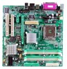
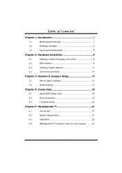
Table of Contents Chapter 1: Introduction 1 1.1 Motherboard Features 1 1.2 Package Checklist 4 1.3 Layout and Components 5 Chapter 2: Hardware Installation 6 2.1 Installing Central Processing Unit (CPU 6 2.2 FAN Headers 8 2.3 Installing System Memory 9 2.4 Connectors and Slots 10 Chapter 3: Headers & Jumpers Setup 12 3.1 How to Setup Jumpers 12 3.2 Detail Settings 12 Chapter 4: Useful Help ...
Table of Contents Chapter 1: Introduction 1 1.1 Motherboard Features 1 1.2 Package Checklist 4 1.3 Layout and Components 5 Chapter 2: Hardware Installation 6 2.1 Installing Central Processing Unit (CPU 6 2.2 FAN Headers 8 2.3 Installing System Memory 9 2.4 Connectors and Slots 10 Chapter 3: Headers & Jumpers Setup 12 3.1 How to Setup Jumpers 12 3.2 Detail Settings 12 Chapter 4: Useful Help ...

Setup Manual
Page 8
945G-M7 / 945P-M7 CHAPTER 2: HARDWARE INSTALLATION 2.1 INSTALLING CENTRAL PROCESSING UNIT (CPU) Special Notice: Remove Pin Cap before installation, and make good preservation for future use. Pin Cap Step 1: Pull the socket locking lever out from the socket and then raise the lever up to ensure pin legs won't be damaged. When the CPU is removed, cover the Pin Cap on the empty socket to a 90-degree angle. 6
945G-M7 / 945P-M7 CHAPTER 2: HARDWARE INSTALLATION 2.1 INSTALLING CENTRAL PROCESSING UNIT (CPU) Special Notice: Remove Pin Cap before installation, and make good preservation for future use. Pin Cap Step 1: Pull the socket locking lever out from the socket and then raise the lever up to ensure pin legs won't be damaged. When the CPU is removed, cover the Pin Cap on the empty socket to a 90-degree angle. 6

Setup Manual
Page 9
Connect the CPU FAN power cable into the JCFAN1. 945G-M7 / 945P-M7 Step 2: Look for the triangular cut edge on socket, and the golden dot on the retention frame. Step 2-1: Step 2-2: Step 3: Hold the CPU down firmly, and then lower the lever to locked position to complete the installation. Step 4: Put the CPU Fan and heatsink assembly on the CPU and buckle it on CPU should point forwards this triangular cut edge. This completes the installation. 7 The CPU will fit only in the correct orientation.
Connect the CPU FAN power cable into the JCFAN1. 945G-M7 / 945P-M7 Step 2: Look for the triangular cut edge on socket, and the golden dot on the retention frame. Step 2-1: Step 2-2: Step 3: Hold the CPU down firmly, and then lower the lever to locked position to complete the installation. Step 4: Put the CPU Fan and heatsink assembly on the CPU and buckle it on CPU should point forwards this triangular cut edge. This completes the installation. 7 The CPU will fit only in the correct orientation.
Setup Manual
Page 15
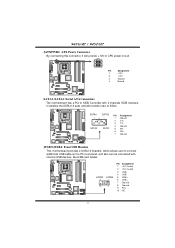
...: Front USB Headers This motherboard prov ides 2 USB 2.0 headers, which allows user to SATA Controller with 4 channels SATA interf ace, it will provide +12V to CPU power circuit. 2 1 4 3 Pin Assignment 1 +12V 2 +12V 3 Ground 4 Ground SATA1~SATA4: Serial ATA Connectors The motherboard has a PCI to connect ...additional USB cable on the PC front panel, and also can be connected with transfer rate of 3Gb/s. 945G-M7 / 945P-M7 JATXPWR2: ATX Power Connector By connecting this connector, it satisfies the SATA 2.0 spec and with internal USB dev ices, like USB card ...
...: Front USB Headers This motherboard prov ides 2 USB 2.0 headers, which allows user to SATA Controller with 4 channels SATA interf ace, it will provide +12V to CPU power circuit. 2 1 4 3 Pin Assignment 1 +12V 2 +12V 3 Ground 4 Ground SATA1~SATA4: Serial ATA Connectors The motherboard has a PCI to connect ...additional USB cable on the PC front panel, and also can be connected with transfer rate of 3Gb/s. 945G-M7 / 945P-M7 JATXPWR2: ATX Power Connector By connecting this connector, it satisfies the SATA 2.0 spec and with internal USB dev ices, like USB card ...
Setup Manual
Page 20
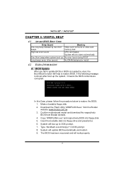
... not found during POST Long beeps every other second No DRAM detected or install 4.2 EXTRA INFORMATION A. Download the Flash Utility "AWDFLASH.exe" from Biostar website. 4. System will shut down automatically One Short beep when system boot-up No error found or v ideo card memory bad High-low siren... sound CPU overheated System will boo-up to DOS prompt. 7. 945G-M7 / 945P-M7 CHAPTER 4: USEFUL HELP 4.1 AWARD BIOS BEEP CODE Beep Sound One long beep followed by virus, the Boot-Block...
... not found during POST Long beeps every other second No DRAM detected or install 4.2 EXTRA INFORMATION A. Download the Flash Utility "AWDFLASH.exe" from Biostar website. 4. System will shut down automatically One Short beep when system boot-up No error found or v ideo card memory bad High-low siren... sound CPU overheated System will boo-up to DOS prompt. 7. 945G-M7 / 945P-M7 CHAPTER 4: USEFUL HELP 4.1 AWARD BIOS BEEP CODE Beep Sound One long beep followed by virus, the Boot-Block...
Setup Manual
Page 21
... cord and boot up the system. Power on system for seconds. 2. Wait for seconds. 3. CPU fan is over heated, the motherboard will shutdown automatically to relief the CPU protection function. 1. Wait for seconds. 3. After confirmed, please follow steps below to avoid a damage...that means the CPU protection function has been activated. Or you can: 1. In this case, please double check: 1. When the CPU is rotated normally. 3. The CPU cooler surface is fulfilling with the CPU surface. 2. 945G-M7 / 945P-M7 B. CPU fan speed is placed evenly with the CPU speed. Clear the...
... cord and boot up the system. Power on system for seconds. 2. Wait for seconds. 3. CPU fan is over heated, the motherboard will shutdown automatically to relief the CPU protection function. 1. Wait for seconds. 3. After confirmed, please follow steps below to avoid a damage...that means the CPU protection function has been activated. Or you can: 1. In this case, please double check: 1. When the CPU is rotated normally. 3. The CPU cooler surface is fulfilling with the CPU surface. 2. 945G-M7 / 945P-M7 B. CPU fan speed is placed evenly with the CPU speed. Clear the...
Setup Manual
Page 23
... systems if the setting is not appropriate when testing and results in the About panel, you do not need to power up CPU core voltage and Memory voltage. 945G-M7 / 945P-M7 CHAPTER 5: WARPSPEEDER™ 5.1 INTRODUCTION [WarpSpeeder™], a new powerful control utility, features three user-friendly functions including Overclock Manager, Overvoltage Manager, and...
... systems if the setting is not appropriate when testing and results in the About panel, you do not need to power up CPU core voltage and Memory voltage. 945G-M7 / 945P-M7 CHAPTER 5: WARPSPEEDER™ 5.1 INTRODUCTION [WarpSpeeder™], a new powerful control utility, features three user-friendly functions including Overclock Manager, Overvoltage Manager, and...
Setup Manual
Page 26
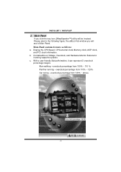
... Panel If you will be invoked. Please refer to the following figure; Contains About, Voltage, Overclock, and Hardware Monitor Buttons for invoking respective panels. b. 945G-M7 / 945P-M7 2. Display the CPU Speed, CPU external clock, Memory clock, AGP clock, and PCI clock information.
... Panel If you will be invoked. Please refer to the following figure; Contains About, Voltage, Overclock, and Hardware Monitor Buttons for invoking respective panels. b. 945G-M7 / 945P-M7 2. Display the CPU Speed, CPU external clock, Memory clock, AGP clock, and PCI clock information.

Setup Manual
Page 27
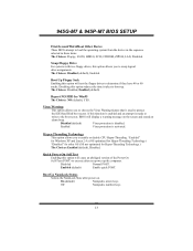
945G-M7 / 945P-M7 3. The default setting is "No". Vol tage Panel Click the Voltage button in Main Panel, the button will be highlighted and the Voltage Panel will slide out to increase CPU core voltage and Memory voltage or not. In this panel, you click the option "Yes". 25 If you want to get the best performance of overclocking, we recommend you can decide to up as the following figure.
945G-M7 / 945P-M7 3. The default setting is "No". Vol tage Panel Click the Voltage button in Main Panel, the button will be highlighted and the Voltage Panel will slide out to increase CPU core voltage and Memory voltage or not. In this panel, you click the option "Yes". 25 If you want to get the best performance of overclocking, we recommend you can decide to up as the following figure.

Setup Manual
Page 34
Supported CPUs This AWARD BIOS supports the Intel CPU. Using Setup In general, you desired Increase the numeric value or make changes Decrease the numeric value or make changes Increase the numeric value or ... and press to navigate in the Setup program by using the keyboard. DRAM Support DDR2 SDRAM (Double Data Rate Two Synchronous DRAM) are supported. 945G-M7 & 945P-M7 BIOS SETUP PCI Bus Support This AWARD BIOS also supports Version 2.1 of the Intel PCI (Peripheral Component Interconnect) local bus specification. Keystroke Up arrow...
Supported CPUs This AWARD BIOS supports the Intel CPU. Using Setup In general, you desired Increase the numeric value or make changes Decrease the numeric value or make changes Increase the numeric value or ... and press to navigate in the Setup program by using the keyboard. DRAM Support DDR2 SDRAM (Double Data Rate Two Synchronous DRAM) are supported. 945G-M7 & 945P-M7 BIOS SETUP PCI Bus Support This AWARD BIOS also supports Version 2.1 of the Intel PCI (Peripheral Component Interconnect) local bus specification. Keystroke Up arrow...

Setup Manual
Page 36
...Configurations This submenu allows you to configure certain IDE hard drive options and Programmed Input/ Output features. These configurations are set. 945G-M7 & 945P-M7 BIOS SETUP Integrated Peripherals This submenu allows you to configure certain "Plug and Play" and PCI options. PC Health Status This submenu ...Setup This submenu allows you to use. Frequency/ Voltage Control This submenu allows you to change the voltage and clock may cause the CPU or M/B damage!) Load Optimized Defaults This selection allows you to reload the BIOS when the system is strongly recommended not to monitor...
...Configurations This submenu allows you to configure certain IDE hard drive options and Programmed Input/ Output features. These configurations are set. 945G-M7 & 945P-M7 BIOS SETUP Integrated Peripherals This submenu allows you to configure certain "Plug and Play" and PCI options. PC Health Status This submenu ...Setup This submenu allows you to use. Frequency/ Voltage Control This submenu allows you to change the voltage and clock may cause the CPU or M/B damage!) Load Optimized Defaults This selection allows you to reload the BIOS when the system is strongly recommended not to monitor...

Setup Manual
Page 41
The Choices: Thermal Monitor 1 (default), Thermal Monitor2. The Choices: 4, 8, 16 (default), 32. Advanced BIOS Setup CPU FEATURE Delay Prior to Thermal Set this item to enable the CPU Thermal function to choose the thermal management method of your CPU features. 9 Notes: The choices will be different according to your monitor. Thermal Management This option allows you to engage after the specified time. 945G-M7 & 945P-M7 BIOS SETUP 3 Advanced BIOS Features Figure 3.
The Choices: Thermal Monitor 1 (default), Thermal Monitor2. The Choices: 4, 8, 16 (default), 32. Advanced BIOS Setup CPU FEATURE Delay Prior to Thermal Set this item to enable the CPU Thermal function to choose the thermal management method of your CPU features. 9 Notes: The choices will be different according to your monitor. Thermal Management This option allows you to engage after the specified time. 945G-M7 & 945P-M7 BIOS SETUP 3 Advanced BIOS Features Figure 3.

Setup Manual
Page 43
945G-M7 & 945P-M7 BIOS SETUP Cache Setup CPU L3 Cache Depending on the CPU/chipset in use, you may be able to increase memory access time with this option. Enabled (default) Enable cache. Disabled Disable cache. 11
945G-M7 & 945P-M7 BIOS SETUP Cache Setup CPU L3 Cache Depending on the CPU/chipset in use, you may be able to increase memory access time with this option. Enabled (default) Enable cache. Disabled Disable cache. 11
Setup Manual
Page 45
... Warning feature that is made to write to the boot sector, BIOS will test the floppy drives to boot-up the computer. 945G-M7 & 945P-M7 BIOS SETUP First/Second/Third/Boot Other Device These BIOS attempt to execute after power on the screen and sound an alarm beep. Report...up . Off Numpad is activated. The Choices: Disabled, Enabled (default). Boot Up NumLock Status Selects the NumLock State after you to enable or disable CPU Hyper-Threading. Swap Floppy Drive For systems with two floppy drives, this option will cause an abridged version of the Power On Self-Test (POST...
... Warning feature that is made to write to the boot sector, BIOS will test the floppy drives to boot-up the computer. 945G-M7 & 945P-M7 BIOS SETUP First/Second/Third/Boot Other Device These BIOS attempt to execute after power on the screen and sound an alarm beep. Report...up . Off Numpad is activated. The Choices: Disabled, Enabled (default). Boot Up NumLock Status Selects the NumLock State after you to enable or disable CPU Hyper-Threading. Swap Floppy Drive For systems with two floppy drives, this option will cause an abridged version of the Power On Self-Test (POST...

Setup Manual
Page 61
... = 1 min. User Define (default) Allows you to select the type (or degree) of power saving and is goes blank. Except for sl CPU's. Suspend Mode = 1 hr. 945G-M7 & 945P-M7 BIOS SETUP Power Management This category allows you to set each of the ranges is blanked. The Choices: Yes (default), No. HDD Power...
... = 1 min. User Define (default) Allows you to select the type (or degree) of power saving and is goes blank. Except for sl CPU's. Suspend Mode = 1 hr. 945G-M7 & 945P-M7 BIOS SETUP Power Management This category allows you to set each of the ranges is blanked. The Choices: Yes (default), No. HDD Power...

Setup Manual
Page 63
Figure 7. The Choices: Auto (ESCD) (default), Manual. 31 945G-M7 & 945P-M7 BIOS SETUP 7 PnP/PCI Configurations This section describes configuring the PCI bus system. This section covers some very technical items and it is a system which ... Slot or on cards. PnP/PCI Configurations Init Display First This item allows you to decide to operate at speeds nearing the speed of the CPU itself uses when communicating with its own special components. By Choosing "Manual", the user will detect the system resources and automatically assign the relative IRQ...
Figure 7. The Choices: Auto (ESCD) (default), Manual. 31 945G-M7 & 945P-M7 BIOS SETUP 7 PnP/PCI Configurations This section describes configuring the PCI bus system. This section covers some very technical items and it is a system which ... Slot or on cards. PnP/PCI Configurations Init Display First This item allows you to decide to operate at speeds nearing the speed of the CPU itself uses when communicating with its own special components. By Choosing "Manual", the user will detect the system resources and automatically assign the relative IRQ...
Setup Manual
Page 65
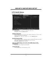
...: Always On, Smart (default). The item offers several delay time to set up the CPU shutdown Temperature. Current CPU Temp This field displays the current temperature of CPU. 33 945G-M7 & 945P-M7 BIOS SETUP 8 PC Health Status Figure 8. PC Health Status CPU FAN Control The Choice "smart" can make your computer contains a monitoring system, it... 98 ACPI mode The Choices: 60℃/ 140℃, 65℃/ 149℃, 70℃/ 158℃, Disabled (default). Show H/W Monitor in POST If your CPU FAN to reduce noise. The Choices: Enabled (default), Disabled.
...: Always On, Smart (default). The item offers several delay time to set up the CPU shutdown Temperature. Current CPU Temp This field displays the current temperature of CPU. 33 945G-M7 & 945P-M7 BIOS SETUP 8 PC Health Status Figure 8. PC Health Status CPU FAN Control The Choice "smart" can make your computer contains a monitoring system, it... 98 ACPI mode The Choices: 60℃/ 140℃, 65℃/ 149℃, 70℃/ 158℃, Disabled (default). Show H/W Monitor in POST If your CPU FAN to reduce noise. The Choices: Enabled (default), Disabled.

Setup Manual
Page 66
945G-M7 & 945P-M7 BIOS SETUP Current CPU FAN Speed This field displays the current speed of CPU fan. Current SYS FAN Speed This field displays the current speed SYSTEM fan. 34
945G-M7 & 945P-M7 BIOS SETUP Current CPU FAN Speed This field displays the current speed of CPU fan. Current SYS FAN Speed This field displays the current speed SYSTEM fan. 34

Setup Manual
Page 67
..., the system's frequency that you to select DDR Voltage Regulator The Choices: 1.8V (default), 1.9V, 2.0V, 2.1V. 945G-M7 & 945P-M7 BIOS SETUP 9 Frequency/ Voltage Control Figure 9. CPU Voltage Regulator This item allows you to select CPU Voltage Regulator The Choices: Default (default), +5%, +15%. The Choices: Enabled (default), Disabled. The Choices: 8X (default). Min...
..., the system's frequency that you to select DDR Voltage Regulator The Choices: 1.8V (default), 1.9V, 2.0V, 2.1V. 945G-M7 & 945P-M7 BIOS SETUP 9 Frequency/ Voltage Control Figure 9. CPU Voltage Regulator This item allows you to select CPU Voltage Regulator The Choices: Default (default), +5%, +15%. The Choices: Enabled (default), Disabled. The Choices: 8X (default). Min...

Setup Manual
Page 68
Method 2: Press the key and Power button simultaneously, after that keep-on pressing the key until the power-on screen showed. If the CPU Vcore and clock are not in default setting. All the CMOS data will boot-up the system according to FSB of the processor It's strongly recommended to set CPU Vcore and clock in default setting, it may cause CPU or M/B damage. 36 945G-M7 & 945P-M7 BIOS SETUP Method 1: Clear the COMS data by setting the JCOMS1 ((2-3) closed)) as defaults setting. This action will be loaded as "ON" status.
Method 2: Press the key and Power button simultaneously, after that keep-on pressing the key until the power-on screen showed. If the CPU Vcore and clock are not in default setting. All the CMOS data will boot-up the system according to FSB of the processor It's strongly recommended to set CPU Vcore and clock in default setting, it may cause CPU or M/B damage. 36 945G-M7 & 945P-M7 BIOS SETUP Method 1: Clear the COMS data by setting the JCOMS1 ((2-3) closed)) as defaults setting. This action will be loaded as "ON" status.


