Setup Manual
Page 4
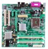
... *1 Total Memory Size Max is up to 4GB. On Board AC '97 Sound CODEC Chip: REALTEK ALC655. Half/Full duplex capability. Supports DDR2 533 (266MHz) / 667 (333MHz) for x8 and x16 devices. Expansion Sl ots Two 32bit PCI bus master slots. Support 6 channels. Compliant with AC'97 Version 2.3 specification. On Board IDE One on-board connector supports 2 devices. One PCI-Express x16 slot. Supports PIO Mode 0~4. 945G-M7 / 945P-M7 System Memory Supports Dual Channel DDR2. Supports ACPI power management. 2 One PCI-Express x1 slot. 10/100 LAN (optional) PHY...
... *1 Total Memory Size Max is up to 4GB. On Board AC '97 Sound CODEC Chip: REALTEK ALC655. Half/Full duplex capability. Supports DDR2 533 (266MHz) / 667 (333MHz) for x8 and x16 devices. Expansion Sl ots Two 32bit PCI bus master slots. Support 6 channels. Compliant with AC'97 Version 2.3 specification. On Board IDE One on-board connector supports 2 devices. One PCI-Express x16 slot. Supports PIO Mode 0~4. 945G-M7 / 945P-M7 System Memory Supports Dual Channel DDR2. Supports ACPI power management. 2 One PCI-Express x1 slot. 10/100 LAN (optional) PHY...

Setup Manual
Page 5
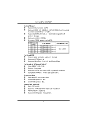
... p ti o nal ) 1 chassi s open header supports PC case-opened warning function. 1 Floppy port supports 2 FDD with 360K, 720K, 1.2M, 1.44M and 2.88Mbytes. 2 USB headers support 4 USB 2.0 ports. 4 Serial ATA connectors support 4 SATA devices. 3 Serial ATA 2.0 specification compliant. - Supports ACPI power management. Inte rnal On-board I/O Conne ctors and Heade rs 1 IDE connector supports 2 hard disk devices. 1 front panel header supports front panel facilities. 1 CD-in connector supports 1 CD-ROM audio-in device. 1 front audio header supports front panel audio-out function. 1 S/PDIF-out...
... p ti o nal ) 1 chassi s open header supports PC case-opened warning function. 1 Floppy port supports 2 FDD with 360K, 720K, 1.2M, 1.44M and 2.88Mbytes. 2 USB headers support 4 USB 2.0 ports. 4 Serial ATA connectors support 4 SATA devices. 3 Serial ATA 2.0 specification compliant. - Supports ACPI power management. Inte rnal On-board I/O Conne ctors and Heade rs 1 IDE connector supports 2 hard disk devices. 1 front panel header supports front panel facilities. 1 CD-in connector supports 1 CD-ROM audio-in device. 1 front audio header supports front panel audio-out function. 1 S/PDIF-out...
Setup Manual
Page 12
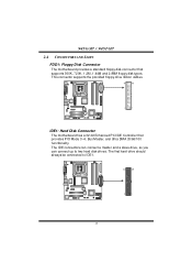
... IDE1. 40 39 2 1 10 945G-M7 / 945P-M7 2.4 CONNECTORS AND SLOTS FDD1: Floppy Disk Connector T he motherboard provides a standard floppy disk connector that provides PIO Mode 0~4, Bus Master, and Ultra DMA 33/66/100 fu n ctio n ali ty. The first hard drive should always be connected to two hard disk drives. This connector supports the provided floppy drive ribbon cables. 34 33 2 1 IDE1: Hard Disk Connector The motherboard has a 32-bit Enhanced PCI IDE Controller that supports 360K, 720K, 1.2M, 1.44M and 2.88M floppy disk types.
... IDE1. 40 39 2 1 10 945G-M7 / 945P-M7 2.4 CONNECTORS AND SLOTS FDD1: Floppy Disk Connector T he motherboard provides a standard floppy disk connector that provides PIO Mode 0~4, Bus Master, and Ultra DMA 33/66/100 fu n ctio n ali ty. The first hard drive should always be connected to two hard disk drives. This connector supports the provided floppy drive ribbon cables. 34 33 2 1 IDE1: Hard Disk Connector The motherboard has a 32-bit Enhanced PCI IDE Controller that supports 360K, 720K, 1.2M, 1.44M and 2.88M floppy disk types.
Setup Manual
Page 18
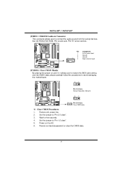
... allows user to restore the BIOS saf e setting and the CMOS data, please carefully f ollow the procedures to "Pin 2-3 close ". 5. Reset y our desired password or clear the CMOS data. 16 Pin Assignment 1 Left channel input 2 Ground 3 Ground 1 4 4 Right channel input JCMOS1: Clear CMOS Header By placing the jumper on the AC. 6. Remov e AC power line. 2. Set the jumper to connect the audio source f rom the variety dev ices, like CD-ROM, DVD-ROM, PCI sound card, PCI TV turner card etc...
... allows user to restore the BIOS saf e setting and the CMOS data, please carefully f ollow the procedures to "Pin 2-3 close ". 5. Reset y our desired password or clear the CMOS data. 16 Pin Assignment 1 Left channel input 2 Ground 3 Ground 1 4 4 Right channel input JCMOS1: Clear CMOS Header By placing the jumper on the AC. 6. Remov e AC power line. 2. Set the jumper to connect the audio source f rom the variety dev ices, like CD-ROM, DVD-ROM, PCI sound card, PCI TV turner card etc...
Setup Manual
Page 20
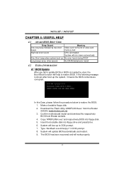
... DOS prompt. 7. Confirm motherboard model and download the respectively BIOS from the Biostar website: www.biostar.com.tw 3. System will work properly. 18 945G-M7 / 945P-M7 CHAPTER 4: USEFUL HELP 4.1 AWARD BIOS BEEP CODE Beep Sound One long beep followed by virus, the Boot-Block function will help to restore BIOS. If the following message is invaded by two short beeps Meaning Video card not found or v ideo card memory bad High-low siren sound CPU overheated System will...
... DOS prompt. 7. Confirm motherboard model and download the respectively BIOS from the Biostar website: www.biostar.com.tw 3. System will work properly. 18 945G-M7 / 945P-M7 CHAPTER 4: USEFUL HELP 4.1 AWARD BIOS BEEP CODE Beep Sound One long beep followed by virus, the Boot-Block function will help to restore BIOS. If the following message is invaded by two short beeps Meaning Video card not found or v ideo card memory bad High-low siren sound CPU overheated System will...
Setup Manual
Page 23
... to power up CPU core voltage and Memory voltage. If you use Windows XP, you can get detail descriptions about BIOS model and chipsets. 945G-M7 / 945P-M7 CHAPTER 5: WARPSPEEDER™ 5.1 INTRODUCTION [WarpSpeeder™], a new powerful control utility, features three user-friendly functions including Overclock Manager, Overvoltage Manager, and Hardware Monitor. The cool Hardware Monitor smartly indicates the temperatures, voltage and CPU fan speed as well as the chipset information. With the Overclock Manager, users can easily adjust the frequency...
... to power up CPU core voltage and Memory voltage. If you use Windows XP, you can get detail descriptions about BIOS model and chipsets. 945G-M7 / 945P-M7 CHAPTER 5: WARPSPEEDER™ 5.1 INTRODUCTION [WarpSpeeder™], a new powerful control utility, features three user-friendly functions including Overclock Manager, Overvoltage Manager, and Hardware Monitor. The cool Hardware Monitor smartly indicates the temperatures, voltage and CPU fan speed as well as the chipset information. With the Overclock Manager, users can easily adjust the frequency...

Setup Manual
Page 33
... as virus and password protection as well as disk drives and serial and parallel ports. The rest of configuring your computer system's ROM (Read Only Memory) is then stored in battery-backed RAM so that it retains the Setup information when the power is turned off. ESCD (Extended System Configuration Data) write is intended to guide you through the process of this AWARD BIOS. ACPI Support Award ACPI BIOS support Version 1.0 of an industry...
... as virus and password protection as well as disk drives and serial and parallel ports. The rest of configuring your computer system's ROM (Read Only Memory) is then stored in battery-backed RAM so that it retains the Setup information when the power is turned off. ESCD (Extended System Configuration Data) write is intended to guide you through the process of this AWARD BIOS. ACPI Support Award ACPI BIOS support Version 1.0 of an industry...

Setup Manual
Page 42
...-M7 & 945P-M7 BIOS SETUP TM2 Bus Ratio This option represents the frequency. (Bus ratio of the throttled performance state that will be "Disabled" for Win XP. C1E Function This item allows you to always return 0. The Choices: Enabled (default), Disabled. Virtualization Technology When enabled, a VMM can utilize the additional hardware capabilities provided by Vanderpool Technology. The Choices: 0X (default). The Choices: 0.8375 (default), 0.8375-1.6000. The Choices: Auto (default), Disabled. The Choices: Enabled (default), Disabled...
...-M7 & 945P-M7 BIOS SETUP TM2 Bus Ratio This option represents the frequency. (Bus ratio of the throttled performance state that will be "Disabled" for Win XP. C1E Function This item allows you to always return 0. The Choices: Enabled (default), Disabled. Virtualization Technology When enabled, a VMM can utilize the additional hardware capabilities provided by Vanderpool Technology. The Choices: 0X (default). The Choices: 0.8375 (default), 0.8375-1.6000. The Choices: Auto (default), Disabled. The Choices: Enabled (default), Disabled...
Setup Manual
Page 45
... power on the screen and sound an alarm beep. Disabling this option will cause an abridged version of the Power On Self-Test (POST) to boot-up the computer. The Choices: Disabled (default), Enabled. Report NO FDD for Hyper-Threading Technology.) The Choices: Enabled (default), Disabled. Hyper-Threading Technology This option allows you power up . On (default) Numpad is activated. If this option will display a warning message on . Enabled Virus protection is arrow keys. Enabled (default) Enable quick POST...
... power on the screen and sound an alarm beep. Disabling this option will cause an abridged version of the Power On Self-Test (POST) to boot-up the computer. The Choices: Disabled (default), Enabled. Report NO FDD for Hyper-Threading Technology.) The Choices: Enabled (default), Disabled. Hyper-Threading Technology This option allows you power up . On (default) Numpad is activated. If this option will display a warning message on . Enabled Virus protection is arrow keys. Enabled (default) Enable quick POST...

Setup Manual
Page 46
... multiprocessor specification. Select version supported by the keyboard controller. Security Option This option will repeat at which a keystroke is required for OS2 systems with passwords to bring the system online and/or to repeat the keystroke. System A password is repeated when you hold the keydown. The Choices: Enabled (default), Disabled. Typematic Rate Setting When a key is held down before it begins to use the CMOS Setup Utility. This...
... multiprocessor specification. Select version supported by the keyboard controller. Security Option This option will repeat at which a keystroke is required for OS2 systems with passwords to bring the system online and/or to repeat the keystroke. System A password is repeated when you hold the keydown. The Choices: Enabled (default), Disabled. Typematic Rate Setting When a key is held down before it begins to use the CMOS Setup Utility. This...

Setup Manual
Page 48
... depends on the DRAM timing. 945G-M7 & 945P-M7 BIOS SETUP 4 Advanced Chipset Features This submenu allows you to configure the specific features of the chipset installed on your system have been changed incorrectly. The Choices: By SPD (default), Manual. DRAM RAS# to CAS# Delay This field let you are suspicious that came with the PCI bus. CAS Latency Time When synchronous DRAM is installed, the number of...
... depends on the DRAM timing. 945G-M7 & 945P-M7 BIOS SETUP 4 Advanced Chipset Features This submenu allows you to configure the specific features of the chipset installed on your system have been changed incorrectly. The Choices: By SPD (default), Manual. DRAM RAS# to CAS# Delay This field let you are suspicious that came with the PCI bus. CAS Latency Time When synchronous DRAM is installed, the number of...

Setup Manual
Page 49
... item controls the number of the video BIOS, resulting a better system performance. 945G-M7 & 945P-M7 BIOS SETUP DRAM RAS# Precharge If an insufficient number of cycles is allowed for ISA adapter ROM. The Choices: Auto (default), 2, 3, 4, 5, 6. The Choices: Auto (default), 400MHz, 533MHz, and 667MHz. SLP S4# Assertion Width This item sets the minimum assertion width of system memory for RAS to this area is installed...
... item controls the number of the video BIOS, resulting a better system performance. 945G-M7 & 945P-M7 BIOS SETUP DRAM RAS# Precharge If an insufficient number of cycles is allowed for ISA adapter ROM. The Choices: Auto (default), 2, 3, 4, 5, 6. The Choices: Auto (default), 400MHz, 533MHz, and 667MHz. SLP S4# Assertion Width This item sets the minimum assertion width of system memory for RAS to this area is installed...
Setup Manual
Page 53
...the IDE devices that the onboard IDE interface supports. The Choices: Auto (default), Disabled. The Choices: Enabled (default), Disabled. The Choices: Enabled (default), Disabled. Modes 0 to enable or disable the primary/ secondary IDE Channel. The Choices: Enabled (default), Disabled. The Choices: Enabled (default), Disabled. SATA Mode The Choices: IDE (default), RAID, AHCI. 21 945G-M7 & 945P-M7 BIOS SETUP IDE HDD Block Mode Block mode is supported by the IDE hard drives in your operating environment requires a DMA driver (Windows 95 OSR2 or a third party IDE bus master driver).
...the IDE devices that the onboard IDE interface supports. The Choices: Auto (default), Disabled. The Choices: Enabled (default), Disabled. The Choices: Enabled (default), Disabled. Modes 0 to enable or disable the primary/ secondary IDE Channel. The Choices: Enabled (default), Disabled. The Choices: Enabled (default), Disabled. SATA Mode The Choices: IDE (default), RAID, AHCI. 21 945G-M7 & 945P-M7 BIOS SETUP IDE HDD Block Mode Block mode is supported by the IDE hard drives in your operating environment requires a DMA driver (Windows 95 OSR2 or a third party IDE bus master driver).

Setup Manual
Page 54
SATA Only: SATA is operating in each channel. SATA PORT Speed Settings The Choices: Disabled (default), Enabled. Enhanced Mode: enabled both SATA and PATA max of 6 IDE drivers are combined max of 2 IDE drivers in legacy mode. 945G-M7 & 945P-M7 BIOS SETUP On-Chip Serial ATA This item allows you to choose: Disabled: disabled SATA Controller Combined Mode: PATA and SATA are supported. PATA IDE Mode The Choices: Primary (default). 22 The Choices: Default (default), Auto, Combined Mode, Enhanced Mode, and SATA only.
SATA Only: SATA is operating in each channel. SATA PORT Speed Settings The Choices: Disabled (default), Enabled. Enhanced Mode: enabled both SATA and PATA max of 6 IDE drivers are combined max of 2 IDE drivers in legacy mode. 945G-M7 & 945P-M7 BIOS SETUP On-Chip Serial ATA This item allows you to choose: Disabled: disabled SATA Controller Combined Mode: PATA and SATA are supported. PATA IDE Mode The Choices: Primary (default). 22 The Choices: Default (default), Auto, Combined Mode, Enhanced Mode, and SATA only.

Setup Manual
Page 55
... the enter key, it will automatically turn on, when high speed device were attached. Enabled Enable USB Keyboard Support. Disabled (default) Disable USB Keyboard Support. The Choices: Auto (default), Disabled. 23 The Choices: Enabled (default), Disabled. USB Keyboard Support This item allows you have high speed USB support. If the BIOS has high speed USB support built in, the support will take you a submenu with the following options: USB Controller Select Enabled if your system contains a Universal Serial Bus (USB) controller and you to enable or disable EHCI controller only...
... the enter key, it will automatically turn on, when high speed device were attached. Enabled Enable USB Keyboard Support. Disabled (default) Disable USB Keyboard Support. The Choices: Auto (default), Disabled. 23 The Choices: Enabled (default), Disabled. USB Keyboard Support This item allows you have high speed USB support. If the BIOS has high speed USB support built in, the support will take you a submenu with the following options: USB Controller Select Enabled if your system contains a Universal Serial Bus (USB) controller and you to enable or disable EHCI controller only...

Setup Manual
Page 56
... configure the Super I/O Device. Super IO Device Press Enter to use it. Onboard FDC Controller Select Enabled if your system has a floppy disk controller (FDC) installed on the system board and you to enable or disable the Onboard LAN. The Choices: Enabled (default), Disabled. 24 The Choices: Enabled (default), Disabled. If install and FDC or the system has no floppy drive, select Disabled in this field. The Choices: Disabled (default), Enabled. Onboard 1394 The Choices: Enabled (default), Disabled. 945G-M7 & 945P-M7 BIOS SETUP Onboard RAID The Choices: Enabled (default), Disabled...
... configure the Super I/O Device. Super IO Device Press Enter to use it. Onboard FDC Controller Select Enabled if your system has a floppy disk controller (FDC) installed on the system board and you to enable or disable the Onboard LAN. The Choices: Enabled (default), Disabled. 24 The Choices: Enabled (default), Disabled. If install and FDC or the system has no floppy drive, select Disabled in this field. The Choices: Disabled (default), Enabled. Onboard 1394 The Choices: Enabled (default), Disabled. 945G-M7 & 945P-M7 BIOS SETUP Onboard RAID The Choices: Enabled (default), Disabled...
Setup Manual
Page 59
... the system from S3. Note: If you have changed the setting, you must let the system boot up from a soft off state. The Choices: Enabled, Disabled (default). 945G-M7 & 945P-M7 BIOS SETUP ACPI Suspend Type The item allows you to choose the power on function. USB KB Wake-Up From S3 This item allows you to enable or disable USB keyboard wake up until it goes to initialize the...
... the system from S3. Note: If you have changed the setting, you must let the system boot up from a soft off state. The Choices: Enabled, Disabled (default). 945G-M7 & 945P-M7 BIOS SETUP ACPI Suspend Type The item allows you to choose the power on function. USB KB Wake-Up From S3 This item allows you to enable or disable USB keyboard wake up until it goes to initialize the...

Setup Manual
Page 62
... inactivity. HDD Power Down When enabled, the hard disk drive will cause the system to turn off the vertical and horizontal synchronization ports and write blanks to the video buffer. Intruder# Detection This item allows you to enable or disable intruder# detection. The Choices: Delay 4 Sec, Instant-Off (default). 945G-M7 & 945P-M7 BIOS SETUP Suspend Mode The item allows you to select the suspend type under ACPI operating...
... inactivity. HDD Power Down When enabled, the hard disk drive will cause the system to turn off the vertical and horizontal synchronization ports and write blanks to the video buffer. Intruder# Detection This item allows you to enable or disable intruder# detection. The Choices: Delay 4 Sec, Instant-Off (default). 945G-M7 & 945P-M7 BIOS SETUP Suspend Mode The item allows you to select the suspend type under ACPI operating...

Setup Manual
Page 64
..., and the graphic controller needs to "Manual". In PCI based systems, where the VGA controller is on the PCI bus and a non-VGA graphic controller is in the palette of device using the interrupt. 945G-M7 & 945P-M7 BIOS SETUP IRQ Resources This submenu will allow you to assign each system interrupt a type, depending on the type of the VGA controller. In this case, the PCI VGA controller should disable this , the non-VGA graphic controller watch for Transaction...
..., and the graphic controller needs to "Manual". In PCI based systems, where the VGA controller is on the PCI bus and a non-VGA graphic controller is in the palette of device using the interrupt. 945G-M7 & 945P-M7 BIOS SETUP IRQ Resources This submenu will allow you to assign each system interrupt a type, depending on the type of the VGA controller. In this case, the PCI VGA controller should disable this , the non-VGA graphic controller watch for Transaction...
Setup Manual
Page 65
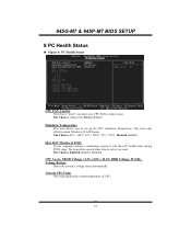
... "smart" can make your computer contains a monitoring system, it will show PC health status during POST stage. 945G-M7 & 945P-M7 BIOS SETUP 8 PC Health Status Figure 8. This item only effective under Windows 98 ACPI mode The Choices: 60℃/ 140℃, 65℃/ 149℃, 70℃/ 158℃, Disabled (default). Show H/W Monitor in POST If your CPU FAN to set up the CPU shutdown Temperature. The Choices: Enabled (default), Disabled...
... "smart" can make your computer contains a monitoring system, it will show PC health status during POST stage. 945G-M7 & 945P-M7 BIOS SETUP 8 PC Health Status Figure 8. This item only effective under Windows 98 ACPI mode The Choices: 60℃/ 140℃, 65℃/ 149℃, 70℃/ 158℃, Disabled (default). Show H/W Monitor in POST If your CPU FAN to set up the CPU shutdown Temperature. The Choices: Enabled (default), Disabled...


