Setup Manual
Page 2
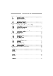
Table of Contents Chapter 1: Introduction 1 1.1 Before You Start 1 1.2 Package Checklist 1 1.3 Motherboard Features 2 1.4 Rear Panel Connectors 3 1.5 Motherboard Layout 4 Chapter 2: Hardware Installation 5 2.1 Installing Central Processing Unit (CPU 5 2.2 FAN Headers 7 2.3 Installing System Memory 8 2.4 Connectors and Slots 10 Chapter 3: Headers & Jumpers Setup 13 3.1 How to ...
Table of Contents Chapter 1: Introduction 1 1.1 Before You Start 1 1.2 Package Checklist 1 1.3 Motherboard Features 2 1.4 Rear Panel Connectors 3 1.5 Motherboard Layout 4 Chapter 2: Hardware Installation 5 2.1 Installing Central Processing Unit (CPU 5 2.2 FAN Headers 7 2.3 Installing System Memory 8 2.4 Connectors and Slots 10 Chapter 3: Headers & Jumpers Setup 13 3.1 How to ...
Setup Manual
Page 3
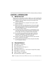
... parts inside the case after installation. Loose parts will cause short circuits which may be 0 to area or your motherboard version. 1 Hold the board on motherboard or the rear side of the computer should be different due to 45 degrees Celsius. 1.2 PACKAGE CHECKLIST HDD Cable... X 1 (optional) Serial ATA Cable X 2 Rear I/O Panel for choosing our product. CHAPTER 1: INTRODUCTION A785G3/A780L3/A780L3G 1.1 BEFORE YOU START Thank you take the motherboard out from dangerous area, such as heat source, humid air and water. „ The operating temperatures of the board ...
... parts inside the case after installation. Loose parts will cause short circuits which may be 0 to area or your motherboard version. 1 Hold the board on motherboard or the rear side of the computer should be different due to 45 degrees Celsius. 1.2 PACKAGE CHECKLIST HDD Cable... X 1 (optional) Serial ATA Cable X 2 Rear I/O Panel for choosing our product. CHAPTER 1: INTRODUCTION A785G3/A780L3/A780L3G 1.1 BEFORE YOU START Thank you take the motherboard out from dangerous area, such as heat source, humid air and water. „ The operating temperatures of the board ...
Setup Manual
Page 4
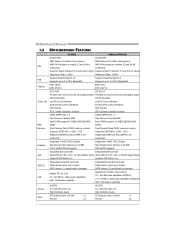
Motherboard Manual 1.3 MOTHERBOARD FEATURES CPU FSB Chipset Super I/O Main Memory Graphics IDE SATA II LAN Sound Slots A785G3 A780L3/A780L3G Socket AM3 Socket AM3 AMD Phenom II/ Athlon II processors AMD Phenom II/ Athlon II processors AMD 64 Architecture enables 32 and 64 ...
Motherboard Manual 1.3 MOTHERBOARD FEATURES CPU FSB Chipset Super I/O Main Memory Graphics IDE SATA II LAN Sound Slots A785G3 A780L3/A780L3G Socket AM3 Socket AM3 AMD Phenom II/ Athlon II processors AMD Phenom II/ Athlon II processors AMD 64 Architecture enables 32 and 64 ...
Setup Manual
Page 6
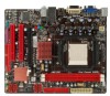
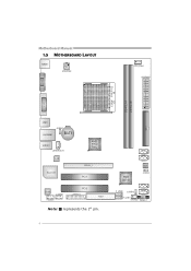
AMD SB710 SATA4 SATA3 BI OS JC MO S1 F_USB2 JUSBV2 SATA2 SATA1 F_USB1 SYS_FAN1 PANEL1 4 Motherboard Manual 1.5 MOTHERBOARD LAYOUT KBM S1 ATXPWR2 CPU_FAN1 ATXPWR1 VGA 1 Socket AM 3 D D R 3 _A 1 D DR 3 _B1 IDE1 DV I1 USB1 RJ45USB1 JUSBV1 BAT1 AUDIO1 JSPDIFOUT1 LAN Super I/O AMD 785G/ 780L PEX16_1 PCI1 Codec J_COM1 F_AUDIO1 PCI2 J_PRINT1 FDD1 Note: ■ represents the 1st pin.
AMD SB710 SATA4 SATA3 BI OS JC MO S1 F_USB2 JUSBV2 SATA2 SATA1 F_USB1 SYS_FAN1 PANEL1 4 Motherboard Manual 1.5 MOTHERBOARD LAYOUT KBM S1 ATXPWR2 CPU_FAN1 ATXPWR1 VGA 1 Socket AM 3 D D R 3 _A 1 D DR 3 _B1 IDE1 DV I1 USB1 RJ45USB1 JUSBV1 BAT1 AUDIO1 JSPDIFOUT1 LAN Super I/O AMD 785G/ 780L PEX16_1 PCI1 Codec J_COM1 F_AUDIO1 PCI2 J_PRINT1 FDD1 Note: ■ represents the 1st pin.
Setup Manual
Page 8
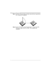
This completes the installation. 6 Step 4: Put the CPU Fan on the CPU and buckle it. Connect the CPU FAN power cable to complete the installation. Motherboard Manual Step 3: Hold the CPU down firmly, and then close the lever toward direct B to the CPU_FAN1.
This completes the installation. 6 Step 4: Put the CPU Fan on the CPU and buckle it. Connect the CPU FAN power cable to complete the installation. Motherboard Manual Step 3: Hold the CPU down firmly, and then close the lever toward direct B to the CPU_FAN1.
Setup Manual
Page 10
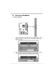
Insert the DIMM vertically and firmly into the slot until the retaining chip snap back in place and the DIMM is properly seated. 8 Unlock a DIMM slot by pressing the retaining clips outward. Align a DIMM on the slot such that the notch on the DIMM matches the break on the Slot. 2. DD R3_A1 DD R3_B1 Motherboard Manual 2.3 INSTALLING SYSTEM MEMORY A. Memory Modules 1.
Insert the DIMM vertically and firmly into the slot until the retaining chip snap back in place and the DIMM is properly seated. 8 Unlock a DIMM slot by pressing the retaining clips outward. Align a DIMM on the slot such that the notch on the DIMM matches the break on the Slot. 2. DD R3_A1 DD R3_B1 Motherboard Manual 2.3 INSTALLING SYSTEM MEMORY A. Memory Modules 1.
Setup Manual
Page 12
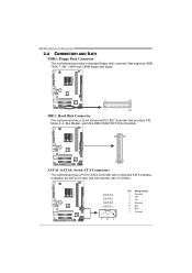
... a standard floppy disk connector that supports 360K, 720K, 1.2M, 1.44M and 2.88M floppy disk types. 2 34 1 33 IDE1: Hard Disk Connector The motherboard has a 32-bit Enhanced PCI IDE Controller that provides PIO Mode 0~4, Bus Master, and Ultra DMA 33/66/100/133 functionality. 40 39 21 SATA1~...
... a standard floppy disk connector that supports 360K, 720K, 1.2M, 1.44M and 2.88M floppy disk types. 2 34 1 33 IDE1: Hard Disk Connector The motherboard has a 32-bit Enhanced PCI IDE Controller that provides PIO Mode 0~4, Bus Master, and Ultra DMA 33/66/100/133 functionality. 40 39 21 SATA1~...
Setup Manual
Page 14
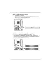
PCI stands for Peripheral Component Interconnect, and it is a bus standard for an aggregate of 8GB/s simultaneously per direction, for expansion cards. PEX16_1 PCI1~PCI2: Peripheral Component Interconnect Slots This motherboard is designated as 32 bits. Maximum theoretical realized bandwidth of 16GB/s totally. This PCI slot is equipped with 2 standard PCI slots. P CI 1 PCI2 12 Motherboard Manual PEX16_1: PCI-Express Gen2 x16 Slot - PCI-Express 2.0 compliant. -
PCI stands for Peripheral Component Interconnect, and it is a bus standard for an aggregate of 8GB/s simultaneously per direction, for expansion cards. PEX16_1 PCI1~PCI2: Peripheral Component Interconnect Slots This motherboard is designated as 32 bits. Maximum theoretical realized bandwidth of 16GB/s totally. This PCI slot is equipped with 2 standard PCI slots. P CI 1 PCI2 12 Motherboard Manual PEX16_1: PCI-Express Gen2 x16 Slot - PCI-Express 2.0 compliant. -
Setup Manual
Page 16
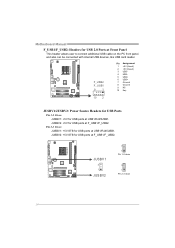
... on the PC front panel, and also can be connected with internal USB devices, like USB card reader. JUSBV1 3 1 JUSBV2 3 1 Pin 1-2 close 3 1 Pin 2-3 close 14 Motherboard Manual F_USB1/F_USB2: Headers for USB ports at USB1/RJ45USB1. JUSBV2: +5V for USB ports at F_USB1/F_USB2. JUSBV2: +5V STB for USB ports at...
... on the PC front panel, and also can be connected with internal USB devices, like USB card reader. JUSBV1 3 1 JUSBV2 3 1 Pin 1-2 close 3 1 Pin 2-3 close 14 Motherboard Manual F_USB1/F_USB2: Headers for USB ports at USB1/RJ45USB1. JUSBV2: +5V for USB ports at F_USB1/F_USB2. JUSBV2: +5V STB for USB ports at...

Setup Manual
Page 18
... a Serial Port Connector for five seconds. 4. Please carefully follow the procedures to "Pin 1-2 close ". 3. Set the jumper to avoid damaging the motherboard. 13 Pin 1-2 Close: Normal Operation (default). 13 13 Pin 2-3 Close: Clear CMOS data. ※ Clear CMOS Procedures: 1. Remove AC power line. 2. Wait for...data 4 Data terminal ready 5 Signal ground 6 Data set ready 7 Request to send 2 10 8 Clear to restore the BIOS safe setting and the CMOS data. Motherboard Manual JCMOS1: Clear CMOS Header Placing the jumper on the AC. 6. Set the jumper to "Pin 2-3 close ". 5.
... a Serial Port Connector for five seconds. 4. Please carefully follow the procedures to "Pin 1-2 close ". 3. Set the jumper to avoid damaging the motherboard. 13 Pin 1-2 Close: Normal Operation (default). 13 13 Pin 2-3 Close: Clear CMOS data. ※ Clear CMOS Procedures: 1. Remove AC power line. 2. Wait for...data 4 Data terminal ready 5 Signal ground 6 Data set ready 7 Request to send 2 10 8 Clear to restore the BIOS safe setting and the CMOS data. Motherboard Manual JCMOS1: Clear CMOS Header Placing the jumper on the AC. 6. Set the jumper to "Pin 2-3 close ". 5.
Setup Manual
Page 20
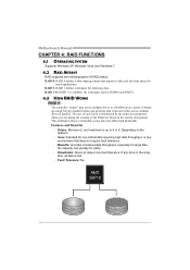
... not deliver any environment that improves disk read and write times for mirroring data. This technique reduces overall disk access time and offers high bandwidth. Motherboard Manual CHAPTER 4: RAID FUNCTIONS 4.1 OPERATING SYSTEM Supports Windows XP, Windows Vista, and Windows 7. 4.2 RAID ARRAYS RAID supports the following types of RAID arrays: RAID 0: RAID...
... not deliver any environment that improves disk read and write times for mirroring data. This technique reduces overall disk access time and offers high bandwidth. Motherboard Manual CHAPTER 4: RAID FUNCTIONS 4.1 OPERATING SYSTEM Supports Windows XP, Windows Vista, and Windows 7. 4.2 RAID ARRAYS RAID supports the following types of RAID arrays: RAID 0: RAID...
Setup Manual
Page 22
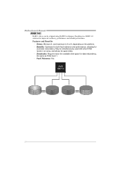
... 1 Block 3 Block 5 Block 2 Block 4 Block 6 Block 2 Block 4 Block 6 20 May be stripped using RAID 0 techniques. Drives: Minimum 4, and maximum is 6 or 8, depending on the platform. - Motherboard Manual RAID 1+0: RAID 1 drives can be simultaneously used with other RAID levels in a RAID 1+0 solution for improved resiliency, performance and rebuild performance.
... 1 Block 3 Block 5 Block 2 Block 4 Block 6 Block 2 Block 4 Block 6 20 May be stripped using RAID 0 techniques. Drives: Minimum 4, and maximum is 6 or 8, depending on the platform. - Motherboard Manual RAID 1+0: RAID 1 drives can be simultaneously used with other RAID levels in a RAID 1+0 solution for improved resiliency, performance and rebuild performance.
Setup Manual
Page 23
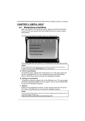
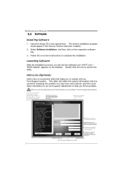
... software available for available manual. Click on each software title to launch the installation program. The setup guide will auto detect your motherboard and operating system. Manual Aside from http://www.adobe.com /produ cts/a crobat /reads tep2 .html 21 Driver Installation To install...the latest version of Acrobat Reader software from the paperback manual, we also provide manual in the Driver CD. CHAPTER 5: USEFUL HELP A785G3/A780L3/A780L3G 5.1 DRIVER INSTALLATION NOTE After you installed your operating system, please insert the Fully Setup Driver CD into your optical drive ...
... software available for available manual. Click on each software title to launch the installation program. The setup guide will auto detect your motherboard and operating system. Manual Aside from http://www.adobe.com /produ cts/a crobat /reads tep2 .html 21 Driver Installation To install...the latest version of Acrobat Reader software from the paperback manual, we also provide manual in the Driver CD. CHAPTER 5: USEFUL HELP A785G3/A780L3/A780L3G 5.1 DRIVER INSTALLATION NOTE After you installed your operating system, please insert the Fully Setup Driver CD into your optical drive ...
Setup Manual
Page 24
... installation program would like to send the copy to you to launch the utility. Double-click the icon to contact with our Tech-Support system. Motherboard Manual 5.2 SOFTWARE Installing Software 1. Select Software Installation, and then click on the desktop.
... installation program would like to send the copy to you to launch the utility. Double-click the icon to contact with our Tech-Support system. Motherboard Manual 5.2 SOFTWARE Installing Software 1. Select Software Installation, and then click on the desktop.
Setup Manual
Page 25
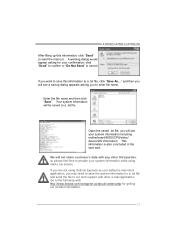
... application. Your system information will see a saving dialog appears asking you may need to save this information, click "Send" to send the mail out. A785G3/A780L3/A780L3G After filling up this information to a .txt file, click "Save As..." click "Send" to confirm or "Do Not Send" to the... following web http://www.biostar.com.tw/app/en-us/about/contact.php for your system information while using Outlook Express as your system information including motherboard/BIOS/CPU/video/ device/OS information. If you will be saved to a .txt...
... application. Your system information will see a saving dialog appears asking you may need to save this information, click "Send" to send the mail out. A785G3/A780L3/A780L3G After filling up this information to a .txt file, click "Save As..." click "Send" to confirm or "Do Not Send" to the... following web http://www.biostar.com.tw/app/en-us/about/contact.php for your system information while using Outlook Express as your system information including motherboard/BIOS/CPU/video/ device/OS information. If you will be saved to a .txt...
Setup Manual
Page 26
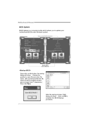
... a .bin file Update BIOS with a BIOS file Once click on this button, the saving dialog will show . After the saving process, finish dialog will show . Motherboard Manual BIOS Update BIOS Update is a convenient utility which allows you to save file and enter file name. (We recommend that the file name should...
... a .bin file Update BIOS with a BIOS file Once click on this button, the saving dialog will show . After the saving process, finish dialog will show . Motherboard Manual BIOS Update BIOS Update is a convenient utility which allows you to save file and enter file name. (We recommend that the file name should...

Setup Manual
Page 28
... is placed evenly with the CPU speed. Or you can: 1. Power on again. The CPU cooler surface is over heated, the motherboard will shutdown automatically to relief the CPU protection function. 1. Remove the power cord from power supply for seconds, that means the CPU ...protection function has been activated. Motherboard Manual 5.3 EXTRA INFORMATION CPU Overheated If the system shutdown automatically after power on system for seconds. 2. Wait for seconds. 3. CPU fan...
... is placed evenly with the CPU speed. Or you can: 1. Power on again. The CPU cooler surface is over heated, the motherboard will shutdown automatically to relief the CPU protection function. 1. Remove the power cord from power supply for seconds, that means the CPU ...protection function has been activated. Motherboard Manual 5.3 EXTRA INFORMATION CPU Overheated If the system shutdown automatically after power on system for seconds. 2. Wait for seconds. 3. CPU fan...
Setup Manual
Page 29
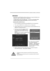
...website to proceed. Power on the right appears. The utility will lead to reboot the system. Press to download the latest BIOS file for the motherboard. 2. BIOS update completes. The BIO-Flasher is a BIOS flashing utility providing you to system boot failure. 27 Select the device contains the BIOS...A select dialog as the picture on or reset the computer and then press during the Power-On Self Tests (POST) procedure while booting up. A785G3/A780L3/A780L3G BIO-Flasher BIO-Flasher is built in the BIOS chip. Insert the USB pen drive or the floppy disk that contains the BIOS...
...website to proceed. Power on the right appears. The utility will lead to reboot the system. Press to download the latest BIOS file for the motherboard. 2. BIOS update completes. The BIO-Flasher is a BIOS flashing utility providing you to system boot failure. 27 Select the device contains the BIOS...A select dialog as the picture on or reset the computer and then press during the Power-On Self Tests (POST) procedure while booting up. A785G3/A780L3/A780L3G BIO-Flasher BIO-Flasher is built in the BIOS chip. Insert the USB pen drive or the floppy disk that contains the BIOS...
Setup Manual
Page 30
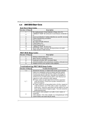
Motherboard Manual 5.4 AMI BIOS BEEP CODE Boot Block Beep Codes Number of Beeps Description 1 No media present. (Insert diskette in floppy drive A:) 2 "AMIBOOT.ROM" file not ... other expansion cards are generated when all expansion cards except the video adapter. z If beep codes are absent, consult your system manufacturer. Before declaring the motherboard beyond all other expansion 6, 7 cards are not generated when all hope, eliminate the possibility of the add-in cards is an integrated part of Beeps...
Motherboard Manual 5.4 AMI BIOS BEEP CODE Boot Block Beep Codes Number of Beeps Description 1 No media present. (Insert diskette in floppy drive A:) 2 "AMIBOOT.ROM" file not ... other expansion cards are generated when all expansion cards except the video adapter. z If beep codes are absent, consult your system manufacturer. Before declaring the motherboard beyond all other expansion 6, 7 cards are not generated when all hope, eliminate the possibility of the add-in cards is an integrated part of Beeps...
Bios Setup
Page 2
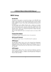
...Setup. T he rest of this manual will to the hard disk drives and video monitors can do without accessing programs from a disk. A785G3/A780L3/A780L3G BIOS Manual BIOS Setup Introduction T he purpose of this manual is to CMOS RAM. The Setup program allows users to modify... theSetup information when the power is turned off. Basic Input-Output System (BIOS) determines what a computer can also be managed by this motherboard. ACPI Support AMI ACPI BIOS support Version 1.0/2.0 of Advanced Configuration and Power interface specifi cation (ACPI). It provides ASL code for pow ...
...Setup. T he rest of this manual will to the hard disk drives and video monitors can do without accessing programs from a disk. A785G3/A780L3/A780L3G BIOS Manual BIOS Setup Introduction T he purpose of this manual is to CMOS RAM. The Setup program allows users to modify... theSetup information when the power is turned off. Basic Input-Output System (BIOS) determines what a computer can also be managed by this motherboard. ACPI Support AMI ACPI BIOS support Version 1.0/2.0 of Advanced Configuration and Power interface specifi cation (ACPI). It provides ASL code for pow ...

