Setup Manual
Page 1
... and to make changes to radio communications. There is not allowed without obligation to notify any implied warranties of this user's manual is subject to provide reasonable protection against harmful interference in a residential installation. A785G3/A780L3/A780L3G Setup Manual FCC Information and Copyright This equipment has been tested and found in this user...
... and to make changes to radio communications. There is not allowed without obligation to notify any implied warranties of this user's manual is subject to provide reasonable protection against harmful interference in a residential installation. A785G3/A780L3/A780L3G Setup Manual FCC Information and Copyright This equipment has been tested and found in this user...
Setup Manual
Page 3
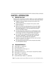
... the computer from power outlet before operation. „ Before you for ATX Case X 1 Installation Guide X 1 Fully Setup Driver CD X 1 (full version manual files inside the case after installation. CHAPTER 1: INTRODUCTION A785G3/A780L3/A780L3G 1.1 BEFORE YOU START Thank you take the motherboard out from dangerous area, such as heat source, humid air and...
... the computer from power outlet before operation. „ Before you for ATX Case X 1 Installation Guide X 1 Fully Setup Driver CD X 1 (full version manual files inside the case after installation. CHAPTER 1: INTRODUCTION A785G3/A780L3/A780L3G 1.1 BEFORE YOU START Thank you take the motherboard out from dangerous area, such as heat source, humid air and...
Setup Manual
Page 4
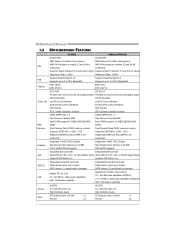
Motherboard Manual 1.3 MOTHERBOARD FEATURES CPU FSB Chipset Super I/O Main Memory Graphics IDE SATA II LAN Sound Slots A785G3 A780L3/A780L3G Socket AM3 Socket AM3 AMD Phenom II/ Athlon II processors AMD Phenom II/ Athlon II processors AMD 64 Architecture enables 32 and 64 ...
Motherboard Manual 1.3 MOTHERBOARD FEATURES CPU FSB Chipset Super I/O Main Memory Graphics IDE SATA II LAN Sound Slots A785G3 A780L3/A780L3G Socket AM3 Socket AM3 AMD Phenom II/ Athlon II processors AMD Phenom II/ Athlon II processors AMD 64 Architecture enables 32 and 64 ...
Setup Manual
Page 6
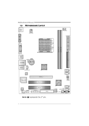
Motherboard Manual 1.5 MOTHERBOARD LAYOUT KBM S1 ATXPWR2 CPU_FAN1 ATXPWR1 VGA 1 Socket AM 3 D D R 3 _A 1 D DR 3 _B1 IDE1 DV I1 USB1 RJ45USB1 JUSBV1 BAT1 AUDIO1 JSPDIFOUT1 LAN Super I/O AMD 785G/ 780L PEX16_1 PCI1 Codec J_COM1 F_AUDIO1 PCI2 J_PRINT1 FDD1 Note: ■ represents the 1st pin. AMD SB710 SATA4 SATA3 BI OS JC MO S1 F_USB2 JUSBV2 SATA2 SATA1 F_USB1 SYS_FAN1 PANEL1 4
Motherboard Manual 1.5 MOTHERBOARD LAYOUT KBM S1 ATXPWR2 CPU_FAN1 ATXPWR1 VGA 1 Socket AM 3 D D R 3 _A 1 D DR 3 _B1 IDE1 DV I1 USB1 RJ45USB1 JUSBV1 BAT1 AUDIO1 JSPDIFOUT1 LAN Super I/O AMD 785G/ 780L PEX16_1 PCI1 Codec J_COM1 F_AUDIO1 PCI2 J_PRINT1 FDD1 Note: ■ represents the 1st pin. AMD SB710 SATA4 SATA3 BI OS JC MO S1 F_USB2 JUSBV2 SATA2 SATA1 F_USB1 SYS_FAN1 PANEL1 4
Setup Manual
Page 8
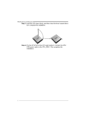
Motherboard Manual Step 3: Hold the CPU down firmly, and then close the lever toward direct B to the CPU_FAN1. Connect the CPU FAN power cable to complete the installation. This completes the installation. 6 Step 4: Put the CPU Fan on the CPU and buckle it.
Motherboard Manual Step 3: Hold the CPU down firmly, and then close the lever toward direct B to the CPU_FAN1. Connect the CPU FAN power cable to complete the installation. This completes the installation. 6 Step 4: Put the CPU Fan on the CPU and buckle it.
Setup Manual
Page 10
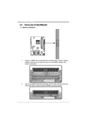
Unlock a DIMM slot by pressing the retaining clips outward. Align a DIMM on the slot such that the notch on the DIMM matches the break on the Slot. 2. Insert the DIMM vertically and firmly into the slot until the retaining chip snap back in place and the DIMM is properly seated. 8 DD R3_A1 DD R3_B1 Motherboard Manual 2.3 INSTALLING SYSTEM MEMORY A. Memory Modules 1.
Unlock a DIMM slot by pressing the retaining clips outward. Align a DIMM on the slot such that the notch on the DIMM matches the break on the Slot. 2. Insert the DIMM vertically and firmly into the slot until the retaining chip snap back in place and the DIMM is properly seated. 8 DD R3_A1 DD R3_B1 Motherboard Manual 2.3 INSTALLING SYSTEM MEMORY A. Memory Modules 1.
Setup Manual
Page 12
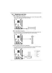
SATA4 SATA3 SATA2 SATA1 Pin Assignment 1 Ground 2 TX+ 3 TX4 Ground 5 RX6 RX+ 7 Ground 74 1 10 Motherboard Manual 2.4 CONNECTORS AND SLOTS FDD1: Floppy Disk Connector The motherboard provides a standard floppy disk connector that supports 360K, 720K, 1.2M, 1.44M and 2.88M floppy disk types. 2 ...
SATA4 SATA3 SATA2 SATA1 Pin Assignment 1 Ground 2 TX+ 3 TX4 Ground 5 RX6 RX+ 7 Ground 74 1 10 Motherboard Manual 2.4 CONNECTORS AND SLOTS FDD1: Floppy Disk Connector The motherboard provides a standard floppy disk connector that supports 360K, 720K, 1.2M, 1.44M and 2.88M floppy disk types. 2 ...
Setup Manual
Page 14
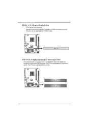
Motherboard Manual PEX16_1: PCI-Express Gen2 x16 Slot - PCI stands for Peripheral Component Interconnect, and it is designated as 32 bits. This PCI slot is a bus standard for an aggregate of 16GB/s totally. PEX16_1 PCI1~PCI2: Peripheral Component Interconnect Slots This motherboard is equipped with 2 standard PCI slots. P CI 1 PCI2 12 Maximum theoretical realized bandwidth of 8GB/s simultaneously per direction, for expansion cards. PCI-Express 2.0 compliant. -
Motherboard Manual PEX16_1: PCI-Express Gen2 x16 Slot - PCI stands for Peripheral Component Interconnect, and it is designated as 32 bits. This PCI slot is a bus standard for an aggregate of 16GB/s totally. PEX16_1 PCI1~PCI2: Peripheral Component Interconnect Slots This motherboard is equipped with 2 standard PCI slots. P CI 1 PCI2 12 Maximum theoretical realized bandwidth of 8GB/s simultaneously per direction, for expansion cards. PCI-Express 2.0 compliant. -
Setup Manual
Page 16
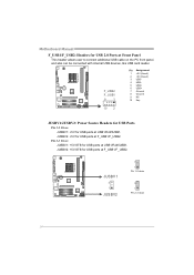
... the PC front panel, and also can be connected with internal USB devices, like USB card reader. JUSBV1 3 1 JUSBV2 3 1 Pin 1-2 close 3 1 Pin 2-3 close 14 Motherboard Manual F_USB1/F_USB2: Headers for USB 2.0 Ports at F_USB1/F_USB2. JUSBV2: +5V for USB ports at USB1/RJ45USB1. Pin 2-3 Close: JUSBV1: +5V STB for USB ports...
... the PC front panel, and also can be connected with internal USB devices, like USB card reader. JUSBV1 3 1 JUSBV2 3 1 Pin 1-2 close 3 1 Pin 2-3 close 14 Motherboard Manual F_USB1/F_USB2: Headers for USB 2.0 Ports at F_USB1/F_USB2. JUSBV2: +5V for USB ports at USB1/RJ45USB1. Pin 2-3 Close: JUSBV1: +5V STB for USB ports...

Setup Manual
Page 18
... CMOS Procedures: 1. Reset your desired password or clear the CMOS data. Power on pin2-3, it allows user to "Pin 1-2 close ". 3. Remove AC power line. 2. Motherboard Manual JCMOS1: Clear CMOS Header Placing the jumper on the AC. 6. Set the jumper to restore the BIOS safe setting and the CMOS data.
... CMOS Procedures: 1. Reset your desired password or clear the CMOS data. Power on pin2-3, it allows user to "Pin 1-2 close ". 3. Remove AC power line. 2. Motherboard Manual JCMOS1: Clear CMOS Header Placing the jumper on the AC. 6. Set the jumper to restore the BIOS safe setting and the CMOS data.
Setup Manual
Page 20
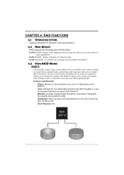
Motherboard Manual CHAPTER 4: RAID FUNCTIONS 4.1 OPERATING SYSTEM Supports Windows XP, Windows Vista, and Windows 7. 4.2 RAID ARRAYS RAID supports the following types of the RAID set during the ...
Motherboard Manual CHAPTER 4: RAID FUNCTIONS 4.1 OPERATING SYSTEM Supports Windows XP, Windows Vista, and Windows 7. 4.2 RAID ARRAYS RAID supports the following types of the RAID set during the ...
Setup Manual
Page 21
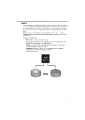
... failure. Drives: Minimum 2, and maximum is actually carried out in parallel across 2 disk drives in the array. Benefits: Provides 100% data redundancy. Fault Tolerance: Yes. A785G3/A780L3/A780L3G RAID 1: Every read and write is 2. - Should one drive. RAID 1 provides a hot-standby copy of data if the active volume or drive is... system. Performance is ideal for high-availability solutions, or as a form of one drive fail, the controller switches to the other application that eliminates tedious manual backups to more expensive and less reliable media.
... failure. Drives: Minimum 2, and maximum is actually carried out in parallel across 2 disk drives in the array. Benefits: Provides 100% data redundancy. Fault Tolerance: Yes. A785G3/A780L3/A780L3G RAID 1: Every read and write is 2. - Should one drive. RAID 1 provides a hot-standby copy of data if the active volume or drive is... system. Performance is ideal for high-availability solutions, or as a form of one drive fail, the controller switches to the other application that eliminates tedious manual backups to more expensive and less reliable media.
Setup Manual
Page 22
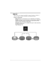
... 6 20 Drives: Minimum 4, and maximum is 6 or 8, depending on the platform. - Drawbacks: Requires twice the available disk space for automatic redundancy. Fault Tolerance: Yes. Motherboard Manual RAID 1+0: RAID 1 drives can be simultaneously used with other RAID levels in a RAID 1+0 solution for improved resiliency, performance and rebuild performance. May be stripped using...
... 6 20 Drives: Minimum 4, and maximum is 6 or 8, depending on the platform. - Drawbacks: Requires twice the available disk space for automatic redundancy. Fault Tolerance: Yes. Motherboard Manual RAID 1+0: RAID 1 drives can be simultaneously used with other RAID levels in a RAID 1+0 solution for improved resiliency, performance and rebuild performance. May be stripped using...
Setup Manual
Page 23
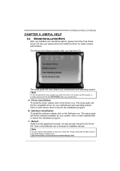
... The setup guide will list the compatible driver for your system, click on each device driver to launch the installation program. B. Manual Aside from http://www.adobe.com /produ cts/a crobat /reads tep2 .html 21 Please download the latest version of Acrobat Reader software...and execute the file SETUP.EXE under your optical drive and install the driver for available manual. Note: You will auto detect your motherboard and operating system. C. CHAPTER 5: USEFUL HELP A785G3/A780L3/A780L3G 5.1 DRIVER INSTALLATION NOTE After you installed your operating system, please insert the ...
... The setup guide will list the compatible driver for your system, click on each device driver to launch the installation program. B. Manual Aside from http://www.adobe.com /produ cts/a crobat /reads tep2 .html 21 Please download the latest version of Acrobat Reader software...and execute the file SETUP.EXE under your optical drive and install the driver for available manual. Note: You will auto detect your motherboard and operating system. C. CHAPTER 5: USEFUL HELP A785G3/A780L3/A780L3G 5.1 DRIVER INSTALLATION NOTE After you installed your operating system, please insert the ...
Setup Manual
Page 24
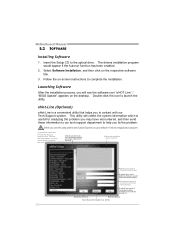
... you will see the software icon "eHOT Line" / "BIOS Update" appears on the desktop. Launching Software After the installation process, you fix the problem. Motherboard Manual 5.2 SOFTWARE Installing Software 1. Provide the name of your system. *Select your default e-mail clientapplication program. *represents important informa ti on of the power suppl y manufacturer...
... you will see the software icon "eHOT Line" / "BIOS Update" appears on the desktop. Launching Software After the installation process, you fix the problem. Motherboard Manual 5.2 SOFTWARE Installing Software 1. Provide the name of your system. *Select your default e-mail clientapplication program. *represents important informa ti on of the power suppl y manufacturer...
Setup Manual
Page 26
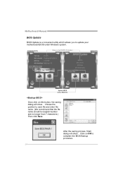
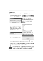
... AWARD BIOS) Save current BIOS to a .bin file Update BIOS with a BIOS file Once click on OK to complete the BIOS Backup procedure. 24 Motherboard Manual BIOS Update BIOS Update is a convenient utility which allows you to save file and enter file name. (We recommend that the file name should be...
... AWARD BIOS) Save current BIOS to a .bin file Update BIOS with a BIOS file Once click on OK to complete the BIOS Backup procedure. 24 Motherboard Manual BIOS Update BIOS Update is a convenient utility which allows you to save file and enter file name. (We recommend that the file name should be...
Setup Manual
Page 27
... shows, press key to be run with the proper BIOS file, and this process may be updated. The utility will show for your reference only. A785G3/A780L3/A780L3G Before doing this, please download the proper BIOS file from this...
... shows, press key to be run with the proper BIOS file, and this process may be updated. The utility will show for your reference only. A785G3/A780L3/A780L3G Before doing this, please download the proper BIOS file from this...

Setup Manual
Page 28
... placed evenly with the CPU speed. Wait for seconds, that means the CPU protection function has been activated. When the CPU is rotated normally. 3. Motherboard Manual 5.3 EXTRA INFORMATION CPU Overheated If the system shutdown automatically after power on system for seconds. 3. The CPU cooler surface is fulfilling with the CPU surface...
... placed evenly with the CPU speed. Wait for seconds, that means the CPU protection function has been activated. When the CPU is rotated normally. 3. Motherboard Manual 5.3 EXTRA INFORMATION CPU Overheated If the system shutdown automatically after power on system for seconds. 3. The CPU cooler surface is fulfilling with the CPU surface...
Setup Manual
Page 30
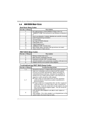
.... Insert the cards back into the system one of the add-in cards is an add-in card, replace or 8 reseat the video adapter. Motherboard Manual 5.4 AMI BIOS BEEP CODE Boot Block Beep Codes Number of Beeps Description 1 No media present. (Insert diskette in floppy drive A:) 2 "AMIBOOT.ROM" file not found...
.... Insert the cards back into the system one of the add-in cards is an add-in card, replace or 8 reseat the video adapter. Motherboard Manual 5.4 AMI BIOS BEEP CODE Boot Block Beep Codes Number of Beeps Description 1 No media present. (Insert diskette in floppy drive A:) 2 "AMIBOOT.ROM" file not found...
Bios Setup
Page 1
A785G3/A780L3/A780L3G BIOS Manual BIOS Setup 1 1 Main Menu 3 2 Advanced Menu 6 3 PCIPnP Menu 16 4 Boot Menu 20 5 Chipset Menu 22 6 Performance Menu 28 7 Exit Menu 37 i
A785G3/A780L3/A780L3G BIOS Manual BIOS Setup 1 1 Main Menu 3 2 Advanced Menu 6 3 PCIPnP Menu 16 4 Boot Menu 20 5 Chipset Menu 22 6 Performance Menu 28 7 Exit Menu 37 i

