Setup Manual
Page 4
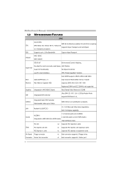
... Controller Ultra DMA 33 / 66 / 100 / 133 Bus Master Mode supports PIO Mode 0~4, SATA II Integrated Serial ATA Controller Data transfer rates up to 3 Gb/s. Motherboard Manual 1.3 MOTHERBOARD FEATURES SPEC Socket AM2 AMD 64 Architecture enables 32 and 64 bit computing CPU AMD Athlon 64 / Athlon 64 FX / Athlon 64 Supports Hyper Transport...
... Controller Ultra DMA 33 / 66 / 100 / 133 Bus Master Mode supports PIO Mode 0~4, SATA II Integrated Serial ATA Controller Data transfer rates up to 3 Gb/s. Motherboard Manual 1.3 MOTHERBOARD FEATURES SPEC Socket AM2 AMD 64 Architecture enables 32 and 64 bit computing CPU AMD Athlon 64 / Athlon 64 FX / Athlon 64 Supports Hyper Transport...

Setup Manual
Page 6
... NOTE 1: NOTE 2: 6 The HDMI and DVI-D ports both can provide digital video signals out-put function, but these ports cannot work at the same time. Motherboard Manual 1.4 REAR PANEL CONNECTORS X PS/2 Mouse Port Y PS/2 Keyboard Port Z S-Video TV-Out Port Transmit analog video signals to TV or any compatible digital audio and...
... NOTE 1: NOTE 2: 6 The HDMI and DVI-D ports both can provide digital video signals out-put function, but these ports cannot work at the same time. Motherboard Manual 1.4 REAR PANEL CONNECTORS X PS/2 Mouse Port Y PS/2 Keyboard Port Z S-Video TV-Out Port Transmit analog video signals to TV or any compatible digital audio and...

Setup Manual
Page 8
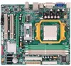
Motherboard Manual CHAPTER 2: HARDWARE INSTALLATION 2.1 INSTALLING CENTRAL PROCESSING UNIT (CPU) Step 1: Remove the socket protection cap. Step 2: Pull the lever toward direction A from the socket and then raise the lever up to a 90-degree angle. The CPU will fit only in the correct orientation. 8 Step 3: Look for the white triangle on socket, and the gold triangle on CPU should point towards this white triangle.
Motherboard Manual CHAPTER 2: HARDWARE INSTALLATION 2.1 INSTALLING CENTRAL PROCESSING UNIT (CPU) Step 1: Remove the socket protection cap. Step 2: Pull the lever toward direction A from the socket and then raise the lever up to a 90-degree angle. The CPU will fit only in the correct orientation. 8 Step 3: Look for the white triangle on socket, and the gold triangle on CPU should point towards this white triangle.

Setup Manual
Page 10
... 1 Ground 2 +12V 3 FAN RPM rate sense Note: The JCFAN1 supports 4-pin head connector. The fan cable and connector may be connected to the fan manufacturer. Motherboard Manual 2.2 FAN HEADERS These fan headers support cooling-fans built in the computer. Connect the fan cable to the connector while matching the black wire to...
... 1 Ground 2 +12V 3 FAN RPM rate sense Note: The JCFAN1 supports 4-pin head connector. The fan cable and connector may be connected to the fan manufacturer. Motherboard Manual 2.2 FAN HEADERS These fan headers support cooling-fans built in the computer. Connect the fan cable to the connector while matching the black wire to...

Setup Manual
Page 12
Motherboard Manual B. Dual Channel Status DIMMA1 DIMMB1 DIMMA2 DIMMB2 Enabled O O X X Enabled X X O O Enabled O O O O (O means memory installed, X means memory not installed.) The DRAM bus width of the memory module must meet the following requirements: Install memory module of the motherboard, the memory module must be the same (x8 or x16) 12 C. Dual Channel Memory installation To...
Motherboard Manual B. Dual Channel Status DIMMA1 DIMMB1 DIMMA2 DIMMB2 Enabled O O X X Enabled X X O O Enabled O O O O (O means memory installed, X means memory not installed.) The DRAM bus width of the memory module must meet the following requirements: Install memory module of the motherboard, the memory module must be the same (x8 or x16) 12 C. Dual Channel Memory installation To...

Setup Manual
Page 14
PCI-Express supports a raw bit-rate of 8GB/s totally. PEX16_1 PEX1_1 PCI1~PCI2: Peripheral Component Interconnect Slots This motherboard is a bus standard for expansion cards. PCI1 PCI2 14 PEX1_1: PCI-Express x1 slots - PCI stands for an aggregate of 2.5GB/s on the data pins. - ... per direction; 500MB/s in total. - Data transfer bandwidth up to 250MB/s per direction, for Peripheral Component Interconnect, and it is equipped with 2 standard PCI slots. Motherboard Manual PEX16_1: PCI-Express x16 Slot - PCI-Express 1.0a compliant. - PCI-Express 1.0a compliant. -
PCI-Express supports a raw bit-rate of 8GB/s totally. PEX16_1 PEX1_1 PCI1~PCI2: Peripheral Component Interconnect Slots This motherboard is a bus standard for expansion cards. PCI1 PCI2 14 PEX1_1: PCI-Express x1 slots - PCI stands for an aggregate of 2.5GB/s on the data pins. - ... per direction; 500MB/s in total. - Data transfer bandwidth up to 250MB/s per direction, for Peripheral Component Interconnect, and it is equipped with 2 standard PCI slots. Motherboard Manual PEX16_1: PCI-Express x16 Slot - PCI-Express 1.0a compliant. - PCI-Express 1.0a compliant. -

Setup Manual
Page 16
Motherboard Manual JATXPWR1: ATX Power Source Connector This connector allows user to connect 24-pin power connector on the ATX power supply. 12 24 Pin Assignment 13 +3....
Motherboard Manual JATXPWR1: ATX Power Source Connector This connector allows user to connect 24-pin power connector on the ATX power supply. 12 24 Pin Assignment 13 +3....

Setup Manual
Page 18
... AC power line. 2. Set the jumper to "Pin 2-3 close ". 5. Reset your desired password or clear the CMOS data. 18 Set the jumper to "Pin 1-2 close ". 3. Motherboard Manual JCDIN1: CD-ROM Audio-in Connector This connector allows user to connect the audio source from the variaty devices, like CD-ROM, DVD-ROM, PCI...
... AC power line. 2. Set the jumper to "Pin 2-3 close ". 5. Reset your desired password or clear the CMOS data. 18 Set the jumper to "Pin 1-2 close ". 3. Motherboard Manual JCDIN1: CD-ROM Audio-in Connector This connector allows user to connect the audio source from the variaty devices, like CD-ROM, DVD-ROM, PCI...

Setup Manual
Page 20
...-232 Port. Pin Assignment 1 +5V 2 SPDIF_OUT 3 Ground 3 1 JSPDIF_IN1: Digital Audio-out Connector (Optional) This connector allows user to connect the PCI bracket SPDIF output header. Motherboard Manual JSPDIF_OUT1: Digital Audio-out Connector This connector allows user to connect the PCI bracket SPDIF input header. Pin Assignment 2 10 1 Carrier detect 2 Received data 3 Transmitted...
...-232 Port. Pin Assignment 1 +5V 2 SPDIF_OUT 3 Ground 3 1 JSPDIF_IN1: Digital Audio-out Connector (Optional) This connector allows user to connect the PCI bracket SPDIF output header. Motherboard Manual JSPDIF_OUT1: Digital Audio-out Connector This connector allows user to connect the PCI bracket SPDIF input header. Pin Assignment 2 10 1 Carrier detect 2 Received data 3 Transmitted...

Setup Manual
Page 22
Motherboard Manual CHAPTER 4: RAID FUNCTIONS 4.1 OPERATION SYSTEM z Supports Windows XP Home/Professional Edition, and Windows Vista. 4.2 RAID ARRAYS RAID supports the following types of the RAID set ...
Motherboard Manual CHAPTER 4: RAID FUNCTIONS 4.1 OPERATION SYSTEM z Supports Windows XP Home/Professional Edition, and Windows Vista. 4.2 RAID ARRAYS RAID supports the following types of the RAID set ...

Setup Manual
Page 24
... 4 Block 6 Block 2 Block 4 Block 6 24 Drawbacks: Requires twice the available disk space for automatic redundancy. Drives: Minimum 4, and maximum is 6 or 8, depending on the platform. - Motherboard Manual RAID 1+0: RAID 1 drives can be simultaneously used with other RAID levels in a RAID 1+0 solution for spare disks. - Features and Benefits -
... 4 Block 6 Block 2 Block 4 Block 6 24 Drawbacks: Requires twice the available disk space for automatic redundancy. Drives: Minimum 4, and maximum is 6 or 8, depending on the platform. - Motherboard Manual RAID 1+0: RAID 1 drives can be simultaneously used with other RAID levels in a RAID 1+0 solution for spare disks. - Features and Benefits -

Setup Manual
Page 26
Manual Overclock System (M.O.S.) MOS is designed for both Elite and Casual overclockers. It allows users to customize personal overclock settings. 26 Overclocking Navigator Engine (O.N.E.): ONE provides two powerful overclocking engines: MOS and AOS for experienced overclock users. Motherboard Manual 5.2 T-POWER BIOS FEATURE A.
Manual Overclock System (M.O.S.) MOS is designed for both Elite and Casual overclockers. It allows users to customize personal overclock settings. 26 Overclocking Navigator Engine (O.N.E.): ONE provides two powerful overclocking engines: MOS and AOS for experienced overclock users. Motherboard Manual 5.2 T-POWER BIOS FEATURE A.

Setup Manual
Page 28
provides 3 ideal overclock configurations that are able to raise the system performance in overclock field, BET had developed an easy, fast, and powerful feature to increase the system performance, named A.O.S. Based on many tests and experiments, A.O.S. Motherboard Manual Automatic Overclock System (A.O.S.) For beginners in a single step. V8 Tech Engine: This setting will raise about 15%~25% of whole system performance. V6 Tech Engine: This setting will raise about 10%~15% of whole system performance. 28
provides 3 ideal overclock configurations that are able to raise the system performance in overclock field, BET had developed an easy, fast, and powerful feature to increase the system performance, named A.O.S. Based on many tests and experiments, A.O.S. Motherboard Manual Automatic Overclock System (A.O.S.) For beginners in a single step. V8 Tech Engine: This setting will raise about 15%~25% of whole system performance. V6 Tech Engine: This setting will raise about 10%~15% of whole system performance. 28

Setup Manual
Page 30
... be changed to "Enable" to proceed this test. ↓ Step 2: Save and Exit from "Enable" to "Disable" to activate this item is under this test. Motherboard Manual C. Memory Integration Test (M.I.T.): This function is "Disabled";
... be changed to "Enable" to proceed this test. ↓ Step 2: Save and Exit from "Enable" to "Disable" to activate this item is under this test. Motherboard Manual C. Memory Integration Test (M.I.T.): This function is "Disabled";

Setup Manual
Page 32
...; CPU Fan Off : If the CPU temperature is under Full Speed. CPU Fan Full speed When CPU temperature arrives to work under "PC Health Status". Motherboard Manual F. CPU Fan Start The CPU fan starts to the set value.
...; CPU Fan Off : If the CPU temperature is under Full Speed. CPU Fan Full speed When CPU temperature arrives to work under "PC Health Status". Motherboard Manual F. CPU Fan Start The CPU fan starts to the set value.

Setup Manual
Page 34
... monitor system voltage, temperature and fan speed accordingly. Hardware Monitor Toolbar i. Start-up . iv. ii. Additionally, a rescue action will be a check icon in system tray. Motherboard Manual 5.3 T-POWER WINDOWS FEATURE A.Hardware Monitor: T-Power Hardware monitor allows users to run Hardware Monitor Program when the Windows starts-up Setting Click on this program...
... monitor system voltage, temperature and fan speed accordingly. Hardware Monitor Toolbar i. Start-up . iv. ii. Additionally, a rescue action will be a check icon in system tray. Motherboard Manual 5.3 T-POWER WINDOWS FEATURE A.Hardware Monitor: T-Power Hardware monitor allows users to run Hardware Monitor Program when the Windows starts-up Setting Click on this program...

Setup Manual
Page 36
.... If battery voltage is only for present status reference. 36 Users can set value, the status line will change to monitor the CPU operating voltage. Motherboard Manual CPU/Battery Voltage i. Also, the system tray icon will alert you . Also, the system tray icon will alert you .
.... If battery voltage is only for present status reference. 36 Users can set value, the status line will change to monitor the CPU operating voltage. Motherboard Manual CPU/Battery Voltage i. Also, the system tray icon will alert you . Also, the system tray icon will alert you .

Setup Manual
Page 38
... increase VGA card performance. A. AGP/PCI-Express Overclocking Setting: By adjusting can configure two items for CPU overclocking. CPU Frequency Range: 200MHz~450MHz. B. B. Interval: 0.1V. Motherboard Manual CPU Overclocking Settings: By adjusting can configure three items for Memory overclocking. Interval: 1. CPU Ratio Range: 4~25. Range: 100MHz~150MHz. CPU Voltage Range: 0.8V~2.0V...
... increase VGA card performance. A. AGP/PCI-Express Overclocking Setting: By adjusting can configure two items for CPU overclocking. CPU Frequency Range: 200MHz~450MHz. B. B. Interval: 0.1V. Motherboard Manual CPU Overclocking Settings: By adjusting can configure three items for Memory overclocking. Interval: 1. CPU Ratio Range: 4~25. Range: 100MHz~150MHz. CPU Voltage Range: 0.8V~2.0V...

Setup Manual
Page 40
... CPU temperature. Calibrate: When changing CPU Fan or System Fan, click on this calibrate function would auto-run to illustrate the fan speed information. ii. Motherboard Manual C. Smart Fan Function When Smart Fan Function is done, the calibrating window will auto-close, and the main screen will pop-up to get upper...
... CPU temperature. Calibrate: When changing CPU Fan or System Fan, click on this calibrate function would auto-run to illustrate the fan speed information. ii. Motherboard Manual C. Smart Fan Function When Smart Fan Function is done, the calibrating window will auto-close, and the main screen will pop-up to get upper...

Setup Manual
Page 42
... pop up to run BIOS flashing process, and it's easy and safe. ii. Motherboard Manual D. Live Update When Live Update program is activated, a screen will link to default setting. 42 Update BIOS: Click on this item will be cleared and returned to Biostar website and BIOS file will clear the CMOS Data. iv.
... pop up to run BIOS flashing process, and it's easy and safe. ii. Motherboard Manual D. Live Update When Live Update program is activated, a screen will link to default setting. 42 Update BIOS: Click on this item will be cleared and returned to Biostar website and BIOS file will clear the CMOS Data. iv.


