Setup Manual
Page 2
Table of Contents Chapter 1: Introduction 1 1.1 Before You Start 1 1.2 Package Checklist 1 1.3 Motherboard Features 2 1.4 Rear Panel Connectors (for Ver 6.x 4 1.5 Rear Panel Connectors (for Ver 5.x 4 1.6 Motherboard Layout (for 945GC-M7 SE 5 1.7 Motherboard Layout (for 945GC Micro 775 6 Chapter 2: Hardware Installation 7 2.1 Installing Central Processing Unit (CPU 7 2.2 FAN Headers 9 2.3 Installing System Memory 10 2.4 Connectors and Slots 12 Chapter 3: Headers & Jumpers Setup 14 3.1 How...
Table of Contents Chapter 1: Introduction 1 1.1 Before You Start 1 1.2 Package Checklist 1 1.3 Motherboard Features 2 1.4 Rear Panel Connectors (for Ver 6.x 4 1.5 Rear Panel Connectors (for Ver 5.x 4 1.6 Motherboard Layout (for 945GC-M7 SE 5 1.7 Motherboard Layout (for 945GC Micro 775 6 Chapter 2: Hardware Installation 7 2.1 Installing Central Processing Unit (CPU 7 2.2 FAN Headers 9 2.3 Installing System Memory 10 2.4 Connectors and Slots 12 Chapter 3: Headers & Jumpers Setup 14 3.1 How...
Setup Manual
Page 3
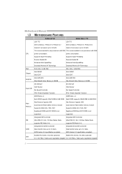
... the rear side of the board unless necessary. 945GC-M7 SE / 945GC Micro 775 CHAPTER 1: INTRODUCTION 1.1 BEFORE YOU START Thank you take the motherboard out from anti-static bag, ground yourself properly by touching any safely grounded appliance, or use ...X 1 (optional) Serial ATA Power Cable X 1 (optional) USB 2.0 Cable X1 (optional) S/PDIF out Cable X 1 (optional) 1 Before you start installing the motherboard, please make sure you follow the instructions below: „ Prepare a dry and stable working environment with sufficient lighting. „ Always disconnect the computer from dangerous...
... the rear side of the board unless necessary. 945GC-M7 SE / 945GC Micro 775 CHAPTER 1: INTRODUCTION 1.1 BEFORE YOU START Thank you take the motherboard out from anti-static bag, ground yourself properly by touching any safely grounded appliance, or use ...X 1 (optional) Serial ATA Power Cable X 1 (optional) USB 2.0 Cable X1 (optional) S/PDIF out Cable X 1 (optional) 1 Before you start installing the motherboard, please make sure you follow the instructions below: „ Prepare a dry and stable working environment with sufficient lighting. „ Always disconnect the computer from dangerous...
Setup Manual
Page 4
... Memory 64 Technology FSB 533 / 800 / 1066 MHz 533 / 800 / 1066 MHz Chipset Intel 945GC Intel ICH7 Intel 945GC Intel ICH7 Graphics Intel GMA 950 Max Shared Video Memory is 224MB Intel GMA 950 Max Shared Video ...LAN 10 / 100 Mb/s / 1Gb/s auto negotiation (Gigabit 10 / 100 Mb/s / 1Gb/s auto negotiation (Gigabit 2 SATA Version 2.0 specification compliant. Motherboard Manual 1.3 MOTHERBOARD FEATURES 945GC-M7 SE 945GC Micro 775 LGA 775 LGA 775 Intel Core2Duo / Pentium 4 / Pentium D / Intel Core2Duo / Pentium 4 / Pentium D / Celeron D processor up to 3.8 GHz Celeron D processor...
... Memory 64 Technology FSB 533 / 800 / 1066 MHz 533 / 800 / 1066 MHz Chipset Intel 945GC Intel ICH7 Intel 945GC Intel ICH7 Graphics Intel GMA 950 Max Shared Video Memory is 224MB Intel GMA 950 Max Shared Video ...LAN 10 / 100 Mb/s / 1Gb/s auto negotiation (Gigabit 10 / 100 Mb/s / 1Gb/s auto negotiation (Gigabit 2 SATA Version 2.0 specification compliant. Motherboard Manual 1.3 MOTHERBOARD FEATURES 945GC-M7 SE 945GC Micro 775 LGA 775 LGA 775 Intel Core2Duo / Pentium 4 / Pentium D / Intel Core2Duo / Pentium 4 / Pentium D / Celeron D processor up to 3.8 GHz Celeron D processor...
Setup Manual
Page 6
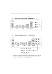
Motherboard Manual 1.4 REAR PANEL CONNECTORS (FOR VER 6.X) PS/2 Mo u se LAN PS/2 K ey bo ard COM1 VGA1 USBX2 USBX2 Line In/ S urro un d Line Out Mic ...
Motherboard Manual 1.4 REAR PANEL CONNECTORS (FOR VER 6.X) PS/2 Mo u se LAN PS/2 K ey bo ard COM1 VGA1 USBX2 USBX2 Line In/ S urro un d Line Out Mic ...
Setup Manual
Page 7
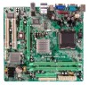
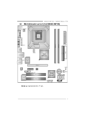
JCMOS1 Intel ICH7 BAT1 JSFAN1 SATA3 SATA1 JUSB3 JUSB4 SATA4 SATA2 JPANEL1 5 945GC-M7 SE / 945GC Micro 775 1.6 MOTHERBOARD LAYOUT (FOR 945GC-M7 SE) JKBMS1 JATXPWR2 LGA775 COJMC1OM1 CPU1 JVGA1 DDR2_A1 DDR2_B1 IDE1 FDD1 JPRNT1 JATXPWR1 JUSB2 JRJ45USB1 JCFAN1 Intel 945GC JAUDIOF1 JAUDIO1 Super I/O PEX16_1 Co dec PEX1_1 BIOS JCDIN1 LAN JSPDIF_OUT PCI1 PCI2 Note: ■ represents the 1st pin.
JCMOS1 Intel ICH7 BAT1 JSFAN1 SATA3 SATA1 JUSB3 JUSB4 SATA4 SATA2 JPANEL1 5 945GC-M7 SE / 945GC Micro 775 1.6 MOTHERBOARD LAYOUT (FOR 945GC-M7 SE) JKBMS1 JATXPWR2 LGA775 COJMC1OM1 CPU1 JVGA1 DDR2_A1 DDR2_B1 IDE1 FDD1 JPRNT1 JATXPWR1 JUSB2 JRJ45USB1 JCFAN1 Intel 945GC JAUDIOF1 JAUDIO1 Super I/O PEX16_1 Co dec PEX1_1 BIOS JCDIN1 LAN JSPDIF_OUT PCI1 PCI2 Note: ■ represents the 1st pin.
Setup Manual
Page 8
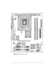
Motherboard Manual 1.7 MOTHERBOARD LAYOUT (FOR 945GC MICRO 775) JKBMS1 JATXPWR2 JKBV1 LGA775 COJMC1OM1 CPU1 JVGA1 DDR2_A1 DDR2_B1 IDE1 FDD1 JPRNT1 JATXPWR1 JUSB2 JUSBV1 JRJ45USB1 JA UDI O2 (for Ver 5.x) AUD IO1 (for Ver 6.x) Super I/O JAUDI OF1 JCFAN1 Intel 945GC PE X1 6_ 1 Co de c PE X1_ 1 BIOS JCDIN1 JSPDIF_OUT PCI1 LAN PCI2 Intel ICH7 JUSBV3_1 JUSB3 JUSB4 Note: ■ represents the 1st pin. JCMOS1 BAT1 JSFAN1 SATA3 SATA1 SATA4 SATA2 JPANEL1 6
Motherboard Manual 1.7 MOTHERBOARD LAYOUT (FOR 945GC MICRO 775) JKBMS1 JATXPWR2 JKBV1 LGA775 COJMC1OM1 CPU1 JVGA1 DDR2_A1 DDR2_B1 IDE1 FDD1 JPRNT1 JATXPWR1 JUSB2 JUSBV1 JRJ45USB1 JA UDI O2 (for Ver 5.x) AUD IO1 (for Ver 6.x) Super I/O JAUDI OF1 JCFAN1 Intel 945GC PE X1 6_ 1 Co de c PE X1_ 1 BIOS JCDIN1 JSPDIF_OUT PCI1 LAN PCI2 Intel ICH7 JUSBV3_1 JUSB3 JUSB4 Note: ■ represents the 1st pin. JCMOS1 BAT1 JSFAN1 SATA3 SATA1 SATA4 SATA2 JPANEL1 6
Setup Manual
Page 10
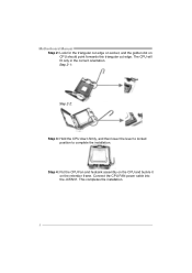
Step 2-1: Step 2-2: Step 3: Hold the CPU down firmly, and then lower the lever to locked position to complete the installation. The CPU will fit only in the correct orientation. Connect the CPU FAN power cable into the JCFAN1. Motherboard Manual Step 2: Look for the triangular cut edge. Step 4: Put the CPU Fan and heatsink assembly on the CPU and buckle it on CPU should point forwards this triangular cut edge on socket, and the golden dot on the retention frame. This completes the installation. 8
Step 2-1: Step 2-2: Step 3: Hold the CPU down firmly, and then lower the lever to locked position to complete the installation. The CPU will fit only in the correct orientation. Connect the CPU FAN power cable into the JCFAN1. Motherboard Manual Step 2: Look for the triangular cut edge. Step 4: Put the CPU Fan and heatsink assembly on the CPU and buckle it on CPU should point forwards this triangular cut edge on socket, and the golden dot on the retention frame. This completes the installation. 8
Setup Manual
Page 12
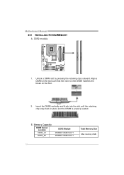
Align a DIMM on the slot such that the notch on the DIMM matches the break on the Slot. 2. Unlock a DIMM slot by pressing the retaining clips outward. Memory Capacity DIMM Socket Location DDR2_A1 DDR2_B1 DDR2 Module 256MB/512MB/1GB *1 256MB/512MB/1GB *1 Total Memory Size Max memory 2GB. 10 B. Motherboard Manual 2.3 INSTALLING SYSTEM MEMORY A. Insert the DIMM vertically and firmly into the slot until the retaining chip snap back in place and the DIMM is properly seated. DDR2 module DDR2_A1 DDR2_B1 1.
Align a DIMM on the slot such that the notch on the DIMM matches the break on the Slot. 2. Unlock a DIMM slot by pressing the retaining clips outward. Memory Capacity DIMM Socket Location DDR2_A1 DDR2_B1 DDR2 Module 256MB/512MB/1GB *1 256MB/512MB/1GB *1 Total Memory Size Max memory 2GB. 10 B. Motherboard Manual 2.3 INSTALLING SYSTEM MEMORY A. Insert the DIMM vertically and firmly into the slot until the retaining chip snap back in place and the DIMM is properly seated. DDR2 module DDR2_A1 DDR2_B1 1.
Setup Manual
Page 13
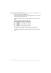
945GC-M7 SE / 945GC Micro 775 C. Dual Channel Memory installation To trigger the Dual Channel function of the same density in pairs, shown in the following table. Dual Channel Status DDR2_A1 DDR2_B1 Disabled O X Disabled X O Enabled O O (O means memory installed, X means memory not installed.) The DRAM bus width of the memory module must meet the following requirements: Install memory module of the motherboard, the memory module must be the same (x8 or x16) 11
945GC-M7 SE / 945GC Micro 775 C. Dual Channel Memory installation To trigger the Dual Channel function of the same density in pairs, shown in the following table. Dual Channel Status DDR2_A1 DDR2_B1 Disabled O X Disabled X O Enabled O O (O means memory installed, X means memory not installed.) The DRAM bus width of the memory module must meet the following requirements: Install memory module of the motherboard, the memory module must be the same (x8 or x16) 11
Setup Manual
Page 14
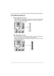
The IDE connector can connect a master and a slave drive, so you can connect up to two hard disk drives. 1 2 39 40 12 This connector supports the provided floppy drive ribbon cables. 1 2 33 34 IDE1: Hard Disk Connectors The motherboard has a 32-bit Enhanced PCI IDE Controller that supports 360K, 720K, 1.2M, 1.44M and 2.88M floppy disk types. Motherboard Manual 2.4 CONNECTORS AND SLOTS FDD1: Floppy Disk Connector The motherboard provides a standard floppy disk connector that provides PIO Mode 0~4, Bus Master, and Ultra DMA 33/66/100 functionality.
The IDE connector can connect a master and a slave drive, so you can connect up to two hard disk drives. 1 2 39 40 12 This connector supports the provided floppy drive ribbon cables. 1 2 33 34 IDE1: Hard Disk Connectors The motherboard has a 32-bit Enhanced PCI IDE Controller that supports 360K, 720K, 1.2M, 1.44M and 2.88M floppy disk types. Motherboard Manual 2.4 CONNECTORS AND SLOTS FDD1: Floppy Disk Connector The motherboard provides a standard floppy disk connector that provides PIO Mode 0~4, Bus Master, and Ultra DMA 33/66/100 functionality.
Setup Manual
Page 15
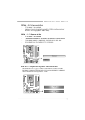
... traditional PCI architecture. PCI1 PCI2 13 PCI-Express 1.0a compliant. - PCI-Express supports a raw bit-rate of 8GB/s totally. 945GC-M7 SE / 945GC Micro 775 PEX16_1: PCI-Express x16 Slot - PEX1_1: PCI-Express x1 Slot - PEX1_1 PEX16_1 PCI1~PCI2: Peripheral Component Interconnect Slots The motherboard is equipped with 2 standard PCI slots. PCI-Express 1.0a compliant. -
... traditional PCI architecture. PCI1 PCI2 13 PCI-Express 1.0a compliant. - PCI-Express supports a raw bit-rate of 8GB/s totally. 945GC-M7 SE / 945GC Micro 775 PEX16_1: PCI-Express x16 Slot - PEX1_1: PCI-Express x1 Slot - PEX1_1 PEX16_1 PCI1~PCI2: Peripheral Component Interconnect Slots The motherboard is equipped with 2 standard PCI slots. PCI-Express 1.0a compliant. -
Setup Manual
Page 16
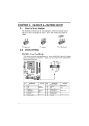
... Header This 16-pin connector includes Power-on, Reset, HDD LED, Power LED, Sleep button, and speaker connections. It allows user to set up jumpers. Motherboard Manual CHAPTER 3: HEADERS & JUMPERS SETUP 3.1 HOW TO SETUP JUMPERS The illustration shows how to connect the PC case's front panel switch functions.
... Header This 16-pin connector includes Power-on, Reset, HDD LED, Power LED, Sleep button, and speaker connections. It allows user to set up jumpers. Motherboard Manual CHAPTER 3: HEADERS & JUMPERS SETUP 3.1 HOW TO SETUP JUMPERS The illustration shows how to connect the PC case's front panel switch functions.
Setup Manual
Page 18
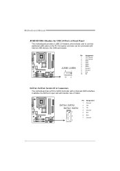
SATA4 SATA2 SATA3 SATA1 1 4 7 Pin Assignment 1 Ground 2 TX+ 3 TX4 Ground 5 RX6 RX+ 7 Ground 16 Motherboard Manual JUSB3/JUSB4: Headers for USB 2.0 Ports at Front Panel This motherboard provides 2 USB 2.0 headers, which allows user to SATA Controller with 4 channels SATA interface, it satisfies the SATA 2.0 spec and...2 Pin Assignment 1 +5V (fused) 2 +5V (fused) 3 USB4 USB5 USB+ 6 USB+ 7 Ground 8 Ground 9 Key 10 NC SATA1~SATA4: Serial ATA Connectors The motherboard has a PCI to connect additional USB cable on the PC front panel, and also can be connected with transfer rate of 3Gb/s.
SATA4 SATA2 SATA3 SATA1 1 4 7 Pin Assignment 1 Ground 2 TX+ 3 TX4 Ground 5 RX6 RX+ 7 Ground 16 Motherboard Manual JUSB3/JUSB4: Headers for USB 2.0 Ports at Front Panel This motherboard provides 2 USB 2.0 headers, which allows user to SATA Controller with 4 channels SATA interface, it satisfies the SATA 2.0 spec and...2 Pin Assignment 1 +5V (fused) 2 +5V (fused) 3 USB4 USB5 USB+ 6 USB+ 7 Ground 8 Ground 9 Key 10 NC SATA1~SATA4: Serial ATA Connectors The motherboard has a PCI to connect additional USB cable on the PC front panel, and also can be connected with transfer rate of 3Gb/s.
Setup Manual
Page 20
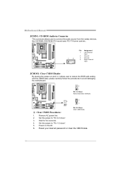
Set the jumper to "Pin 1-2 close ". 3. Set the jumper to "Pin 2-3 close ". 5. Motherboard Manual JCDIN1: CD-ROM Audio-in Connector This connector allows user to connect the audio source from the variaty devices, like CD-ROM, DVD-ROM,.... 6. Power on pin2-3, it allows user to restore the BIOS safe setting and the CMOS data, please carefully follow the procedures to avoid damaging the motherboard. 3 1 Pin 1-2 Close: Normal Operation (Default). 3 3 1 1 ※ Clear CMOS Procedures: Pin 2-3 Close: Clear CMOS data. 1. Remove AC power line. 2. Wait for five seconds. 4. Reset your ...
Set the jumper to "Pin 1-2 close ". 3. Set the jumper to "Pin 2-3 close ". 5. Motherboard Manual JCDIN1: CD-ROM Audio-in Connector This connector allows user to connect the audio source from the variaty devices, like CD-ROM, DVD-ROM,.... 6. Power on pin2-3, it allows user to restore the BIOS safe setting and the CMOS data, please carefully follow the procedures to avoid damaging the motherboard. 3 1 Pin 1-2 Close: Normal Operation (Default). 3 3 1 1 ※ Clear CMOS Procedures: Pin 2-3 Close: Clear CMOS data. 1. Remove AC power line. 2. Wait for five seconds. 4. Reset your ...
Setup Manual
Page 22
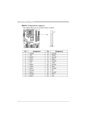
Motherboard Manual JPRNT1: Printer Port Connector This header allows you to connector printer on the PC. 25 Pin Assignment 1 -Strobe 2 -ALF 3 Data 0 4 -Error 5 Data 1 6 -Init 7 Data 2 8 -Scltin 9 Data 3 10 Ground 11 Data 4 12 Ground 13 Data 5 2 1 Pin Assignment 14 Ground 15 Data 6 16 Ground 17 Data 7 18 Ground 19 -ACK 20 Ground 21 Busy 22 Ground 23 PE 24 Ground 25 SCLT 26 Key 20
Motherboard Manual JPRNT1: Printer Port Connector This header allows you to connector printer on the PC. 25 Pin Assignment 1 -Strobe 2 -ALF 3 Data 0 4 -Error 5 Data 1 6 -Init 7 Data 2 8 -Scltin 9 Data 3 10 Ground 11 Data 4 12 Ground 13 Data 5 2 1 Pin Assignment 14 Ground 15 Data 6 16 Ground 17 Data 7 18 Ground 19 -ACK 20 Ground 21 Busy 22 Ground 23 PE 24 Ground 25 SCLT 26 Key 20
Setup Manual
Page 23
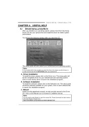
... Aside from http://www.adobe.com /produ cts/a crobat /reads tep2 .html 21 A. 945GC-M7 SE / 945GC Micro 775 CHAPTER 4: USEFUL HELP 4.1 DRIVER INSTALLATION NOTE After you installed your operating system, please insert the Fully Setup Driver CD into your motherboard and operating system. C. You will need Acrobat Reader to locate and execute the file...
... Aside from http://www.adobe.com /produ cts/a crobat /reads tep2 .html 21 A. 945GC-M7 SE / 945GC Micro 775 CHAPTER 4: USEFUL HELP 4.1 DRIVER INSTALLATION NOTE After you installed your operating system, please insert the Fully Setup Driver CD into your motherboard and operating system. C. You will need Acrobat Reader to locate and execute the file...
Setup Manual
Page 24
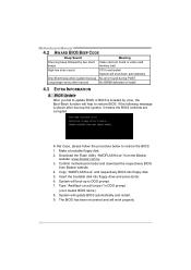
...during POST Long beeps every other second No DRAM detected or install 4.3 EXTRA INFORMATION A. Download the Flash Utility "AWDFLASH.exe" from Biostar website. 4. System will boot-up the system, it means the BIOS contents are corrupted. BIOS Update After you fail to update BIOS... BIOS into floppy drive and press Enter. 6. The BIOS has been recovered and will update BIOS automatically and restart. 9. Confirm motherboard model and download the respectively BIOS from the Biostar website: www.biostar.com.tw 3. Type "Awdflash xxxx.bf/sn/py/r" in DOS prompt. (xxxx means BIOS name...
...during POST Long beeps every other second No DRAM detected or install 4.3 EXTRA INFORMATION A. Download the Flash Utility "AWDFLASH.exe" from Biostar website. 4. System will boot-up the system, it means the BIOS contents are corrupted. BIOS Update After you fail to update BIOS... BIOS into floppy drive and press Enter. 6. The BIOS has been recovered and will update BIOS automatically and restart. 9. Confirm motherboard model and download the respectively BIOS from the Biostar website: www.biostar.com.tw 3. Type "Awdflash xxxx.bf/sn/py/r" in DOS prompt. (xxxx means BIOS name...
Setup Manual
Page 25
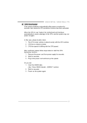
..." section) 2. In this case, please double check: 1. 945GC-M7 SE / 945GC Micro 775 B. Wait for seconds. 3. After confirmed, please follow steps below to avoid a damage of the CPU, and the system may not power on the system again. 23 CPU fan speed is over heated, the motherboard will shutdown automatically to relief the CPU 0protection...
..." section) 2. In this case, please double check: 1. 945GC-M7 SE / 945GC Micro 775 B. Wait for seconds. 3. After confirmed, please follow steps below to avoid a damage of the CPU, and the system may not power on the system again. 23 CPU fan speed is over heated, the motherboard will shutdown automatically to relief the CPU 0protection...
Setup Manual
Page 26
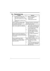
Motherboard Manual 4.4 TROUBLESHOOTING Probable Solution 1. inside power supply does not turn on. Using even pressure on keyboard does not turn 2. Reformat the hard drive. Screen message ...
Motherboard Manual 4.4 TROUBLESHOOTING Probable Solution 1. inside power supply does not turn on. Using even pressure on keyboard does not turn 2. Reformat the hard drive. Screen message ...
Setup Manual
Page 28
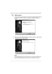
When you see the following dialog in this user manual will pop up. Execute the setup execution file, and then the following figures are only for reference, the screen printed in setup procedure, it means setup is completed. Click "Finish" button. Please click "Next" button and follow the default procedure to your motherboard on hand. 26 Usage: The following dialog will change according to install. 2. Motherboard Manual 5.3 INSTALLATION 1.
When you see the following dialog in this user manual will pop up. Execute the setup execution file, and then the following figures are only for reference, the screen printed in setup procedure, it means setup is completed. Click "Finish" button. Please click "Next" button and follow the default procedure to your motherboard on hand. 26 Usage: The following dialog will change according to install. 2. Motherboard Manual 5.3 INSTALLATION 1.

