Setup Manual
Page 4
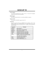
H/W Monitor Fan Speed Controller Low Pin Count Interface ITE's "Smart Guardian" function DIMM Slots x 2 Main Memory Each DIMM supports 256/512MB & 1GB DDR2 Max Memory Capacity 2GB Dual Channel Mode DDR2 memory module Registered DIMM and ECC...1 Printer port SATA Connector x4 Each connector supports 1 SATA devices 2 SATA Version 2.0 specification compliant. FSB 533 / 800 / 1066 / 1333 MHz Chipset Intel 945GC Intel ICH7 Graphics Intel GMA 950 Max Shared Video Memory is 224MB ITE IT8712F Environment Control initiatives, Provides the most commonly used legacy Super I/O Super...
H/W Monitor Fan Speed Controller Low Pin Count Interface ITE's "Smart Guardian" function DIMM Slots x 2 Main Memory Each DIMM supports 256/512MB & 1GB DDR2 Max Memory Capacity 2GB Dual Channel Mode DDR2 memory module Registered DIMM and ECC...1 Printer port SATA Connector x4 Each connector supports 1 SATA devices 2 SATA Version 2.0 specification compliant. FSB 533 / 800 / 1066 / 1333 MHz Chipset Intel 945GC Intel ICH7 Graphics Intel GMA 950 Max Shared Video Memory is 224MB ITE IT8712F Environment Control initiatives, Provides the most commonly used legacy Super I/O Super...
Setup Manual
Page 24
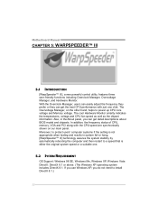
... not need to protect users' computer systems if the setting is either the original system speed or a suitable one click. The Overvoltage Manager, on our main panel. Moreover, to install DirectX 8.1.) 22 Motherboard Manual CHAPTER 5: WARPSPEEDER™ III 5.1 INTRODUCTION [WarpSpeeder™ III], a new powerful control utility, features three user-friendly functions...
... not need to protect users' computer systems if the setting is either the original system speed or a suitable one click. The Overvoltage Manager, on our main panel. Moreover, to install DirectX 8.1.) 22 Motherboard Manual CHAPTER 5: WARPSPEEDER™ III 5.1 INTRODUCTION [WarpSpeeder™ III], a new powerful control utility, features three user-friendly functions...
Setup Manual
Page 26
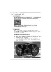
...clock information. Now you double-click the desktop icon, [WarpSpeeder™ III] will see is for invoking respective panels. Main Panel If you can launch the [WarpSpeeder™ III] utility simply by double-clicking the desktop icon. 2. The On/Off button is... Main Panel. Please refer to the following figure; Main Panel contains features as follows: a. b. Motherboard Manual 5.4 WARPSPEEDER™ III 1. Desktop Icon After the [WarpSpeeder™ III]...
...clock information. Now you double-click the desktop icon, [WarpSpeeder™ III] will see is for invoking respective panels. Main Panel If you can launch the [WarpSpeeder™ III] utility simply by double-clicking the desktop icon. 2. The On/Off button is... Main Panel. Please refer to the following figure; Main Panel contains features as follows: a. b. Motherboard Manual 5.4 WARPSPEEDER™ III 1. Desktop Icon After the [WarpSpeeder™ III]...
Setup Manual
Page 27
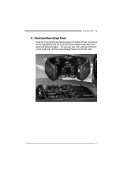
945GC-M7 TE 3. Overclock/Overvoltage Panel Click the Overclock/Overvoltage button in the Main Panel, the button will be highlighted and the Overclock/Overvoltage Panel will show up as the following figure. As you can see, the Overclock Panel is on the right side, and the Overvoltage Panel is on the left side. 25
945GC-M7 TE 3. Overclock/Overvoltage Panel Click the Overclock/Overvoltage button in the Main Panel, the button will be highlighted and the Overclock/Overvoltage Panel will show up as the following figure. As you can see, the Overclock Panel is on the right side, and the Overvoltage Panel is on the left side. 25

Setup Manual
Page 29
945GC-M7 TE Overvoltage Panel contains these features: a. Click on "+" to increase or "-" to decrease the Memory voltage. 4. In this panel, you can get the real-time status information of your system. Hardware Monitor Panel Click the Hardware Monitor button in Main Panel, the button will be highlighted and the Hardware Monitor panel...
945GC-M7 TE Overvoltage Panel contains these features: a. Click on "+" to increase or "-" to decrease the Memory voltage. 4. In this panel, you can get the real-time status information of your system. Hardware Monitor Panel Click the Hardware Monitor button in Main Panel, the button will be highlighted and the Hardware Monitor panel...

Setup Manual
Page 30
... will be highlighted and the About Panel will not interfere other panels' functions. If one chipset is not on board, the correlative button in Main Panel, the button will be disabled, but will show up as the following figure. In this panel, you can make [WarpSpeeder™ III] utility more ...
... will be highlighted and the About Panel will not interfere other panels' functions. If one chipset is not on board, the correlative button in Main Panel, the button will be disabled, but will show up as the following figure. In this panel, you can make [WarpSpeeder™ III] utility more ...
Bios Setup
Page 1
945GC-M7 TE BIOS SETUP BIOS Setup 1 1 Main Menu...3 2 Standard CMOS Features 6 3 Advanced BIOS Features 8 4 Advanced Chipset Features 13 5 Integrated Peripherals 16 6 Power Management Setup 21 7 PnP/PCI Configurations 26 8 PC Health Status 28 9 Frequency/Voltage Control 30 i
945GC-M7 TE BIOS SETUP BIOS Setup 1 1 Main Menu...3 2 Standard CMOS Features 6 3 Advanced BIOS Features 8 4 Advanced Chipset Features 13 5 Integrated Peripherals 16 6 Power Management Setup 21 7 PnP/PCI Configurations 26 8 PC Health Status 28 9 Frequency/Voltage Control 30 i
Bios Setup
Page 3
...PgUp key PgDn key + Key - Supported CPUs This PHOENIX-AWARD BIOS supports the Intel CPU. The following table provides more detail about how to Main Menu General help and press to the item you desired Increase the numeric value or make changes Decrease the numeric value or make changes Increase... the numeric value or make changes Decrease the numeric value or make changes Main Menu - Exit Current page and return to navigate in the Setup program by using the keyboard. 945GC-M7 TE PCI Bus Support This PHOENIX-AWARD BIOS also supports Version 2.3 of the Intel PCI ...
...PgUp key PgDn key + Key - Supported CPUs This PHOENIX-AWARD BIOS supports the Intel CPU. The following table provides more detail about how to Main Menu General help and press to the item you desired Increase the numeric value or make changes Decrease the numeric value or make changes Increase... the numeric value or make changes Decrease the numeric value or make changes Main Menu - Exit Current page and return to navigate in the Setup program by using the keyboard. 945GC-M7 TE PCI Bus Support This PHOENIX-AWARD BIOS also supports Version 2.3 of the Intel PCI ...

Bios Setup
Page 4
...the BIOS installed on the screen. Advanced Chipset Features This submenu allows you to select from several setup functions. WARNING !! The Main Menu allows you to configure special chipset features. 3 Advanced BIOS Features This submenu allows you enter Phoenix-Award BIOS™ CMOS Setup... Utility, the Main Menu will appear on board, for reference, please refer to accept and enter the sub-menu. !! 945GC-M7 TE 1 Main Menu Once you to configure enhanced features of the BIOS. Main Menu Standard CMOS Features This submenu contains industry ...
...the BIOS installed on the screen. Advanced Chipset Features This submenu allows you to select from several setup functions. WARNING !! The Main Menu allows you to configure special chipset features. 3 Advanced BIOS Features This submenu allows you enter Phoenix-Award BIOS™ CMOS Setup... Utility, the Main Menu will appear on board, for reference, please refer to accept and enter the sub-menu. !! 945GC-M7 TE 1 Main Menu Once you to configure enhanced features of the BIOS. Main Menu Standard CMOS Features This submenu contains industry ...

Bios Setup
Page 7
...of detailed options IDE Channel 0 Slave Options are in each item. „ Figure 2. Note that you can make on the Main Menu. Standard CMOS Setup Main Menu Selections This table shows the selections that the 'Day' automatically changes when you want in its sub Press to select the ...value you set the date. IDE Channel 0 Master Options are in Standard CMOS Setup Menu are divided into 10 categories. 945GC-M7 TE 2...
...of detailed options IDE Channel 0 Slave Options are in each item. „ Figure 2. Note that you can make on the Main Menu. Standard CMOS Setup Main Menu Selections This table shows the selections that the 'Day' automatically changes when you want in its sub Press to select the ...value you set the date. IDE Channel 0 Master Options are in Standard CMOS Setup Menu are divided into 10 categories. 945GC-M7 TE 2...
Bios Setup
Page 13
... when system boot up . APIC Mode Selecting Enabled enables APIC device mode reporting from the Setup main menu. The Choices: Enabled, Disabled (default). 12 Disab led No "Small Logo" shows when system boots up . 945GC-M7 TE Typematic Delay (Msec) Sets the delay time after the key is only used for the...
... when system boot up . APIC Mode Selecting Enabled enables APIC device mode reporting from the Setup main menu. The Choices: Enabled, Disabled (default). 12 Disab led No "Small Logo" shows when system boots up . 945GC-M7 TE Typematic Delay (Msec) Sets the delay time after the key is only used for the...