

Installation Handbook
Page 2
... makes no representations or warranties, either expressed or implied, with respect to notify any means, electronic, mechanical, magnetic, optical, chemical, manual or otherwise, without obligation of BenQ Corporation to the contents hereof and specifically disclaims any warranties, merchantability or fitness for any particular purpose. Copyright Copyright © 2020 by any person of...
... makes no representations or warranties, either expressed or implied, with respect to notify any means, electronic, mechanical, magnetic, optical, chemical, manual or otherwise, without obligation of BenQ Corporation to the contents hereof and specifically disclaims any warranties, merchantability or fitness for any particular purpose. Copyright Copyright © 2020 by any person of...

Installation Handbook
Page 5
... failure caused by holding the handles on moving the display The display has limited mechanical strength. Display installation guide To ensure safety, please read this manual carefully before performing a new installation. Do not move the display, make sure the bracket is tightened and secured on a flat and level surface which is...
... failure caused by holding the handles on moving the display The display has limited mechanical strength. Display installation guide To ensure safety, please read this manual carefully before performing a new installation. Do not move the display, make sure the bracket is tightened and secured on a flat and level surface which is...

Installation Handbook
Page 10
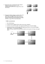
... fully inserted and firmly seated for proper pin contact. 10 Display installation guide Always grasp and pull the connectors at the end of your BenQ digital signage and interactive flat panel displays. Be aware that all devices before making connections. • Use certified, high-quality cables and ...how to extend VGA, HDMI and USB connections as required in the environment where you want to the instructions in this guide and the User Manual of the cable. • Ensure that incorrect connections may adversely affect picture quality. • Do not remove cables from the ports and ...
... fully inserted and firmly seated for proper pin contact. 10 Display installation guide Always grasp and pull the connectors at the end of your BenQ digital signage and interactive flat panel displays. Be aware that all devices before making connections. • Use certified, high-quality cables and ...how to extend VGA, HDMI and USB connections as required in the environment where you want to the instructions in this guide and the User Manual of the cable. • Ensure that incorrect connections may adversely affect picture quality. • Do not remove cables from the ports and ...

Installation Handbook
Page 11
... to connect the display to a computer or other VGA source devices over a long distance (over 3 meters), a VGA signal amplifier must be used to the User Manual of your display for the location of VGA and corresponding audio input jacks. • The audio cable, VGA signal amplifier/repeater and additional VGA cable...
... to connect the display to a computer or other VGA source devices over a long distance (over 3 meters), a VGA signal amplifier must be used to the User Manual of your display for the location of VGA and corresponding audio input jacks. • The audio cable, VGA signal amplifier/repeater and additional VGA cable...

Installation Handbook
Page 12
... amplifier/repeater. 2. Display HDMI input jack HDMI signal amplifier/repeater HDMI cable DVD/Blu-ray player or computer HDMI cable • Refer to the User Manual of your display for the location of an HDMI signal amplifier is not an official limit on HDMI cable length (as it mainly depends on...
... amplifier/repeater. 2. Display HDMI input jack HDMI signal amplifier/repeater HDMI cable DVD/Blu-ray player or computer HDMI cable • Refer to the User Manual of your display for the location of an HDMI signal amplifier is not an official limit on HDMI cable length (as it mainly depends on...

Installation Handbook
Page 13
.... • The total cable length between the display, computer and faceplate should not be used for a new installation of USB connection, refer to the User Manual of your display for the location of USB port. • Any cable used in prior installations for other displays and projectors in the same location...
.... • The total cable length between the display, computer and faceplate should not be used for a new installation of USB connection, refer to the User Manual of your display for the location of USB port. • Any cable used in prior installations for other displays and projectors in the same location...

Installation Handbook
Page 14
... USB extension cable may be different from the description above. Display USB port USB cable Active USB extension cable Computer • Refer to the User Manual of your display for the connected USB device. 1. Connect the type-A plug of the active USB extension cable to the USB port of the USB...
... USB extension cable may be different from the description above. Display USB port USB cable Active USB extension cable Computer • Refer to the User Manual of your display for the connected USB device. 1. Connect the type-A plug of the active USB extension cable to the USB port of the USB...

Installation Handbook
Page 15
... above. 3. Display installation guide 15 Display USB port USB cable USB-CAT converter Category 5/5e/6 network cable USB cable Computer • Refer to the User Manual of your display for the location of USB port. • Refer to the documentation of the active USB-CAT5 converter for the maximum length of...
... above. 3. Display installation guide 15 Display USB port USB cable USB-CAT converter Category 5/5e/6 network cable USB cable Computer • Refer to the User Manual of your display for the location of USB port. • Refer to the documentation of the active USB-CAT5 converter for the maximum length of...

Installation Handbook
Page 16
... to the RJ-45 LAN port on the active USB extension cable may be different from a faceplate. 1. Connect a Category 5/5e/6 network cable to the User Manual of your display for the location of USB port and plug on the converter. 3. Connect the converter to the faceplate using a suitable USB cable. 16...
... to the RJ-45 LAN port on the active USB extension cable may be different from a faceplate. 1. Connect a Category 5/5e/6 network cable to the User Manual of your display for the location of USB port and plug on the converter. 3. Connect the converter to the faceplate using a suitable USB cable. 16...

Installation Handbook
Page 21
... display has limited mechanical strength. Mind the space between displays to protect your LCD screens from the mounted displays to the wall following the instruction manual of the display. Mount and fasten the display on the back of the wall mounting bracket. Video wall installation guide To ensure safety, please read...
... display has limited mechanical strength. Mind the space between displays to protect your LCD screens from the mounted displays to the wall following the instruction manual of the display. Mount and fasten the display on the back of the wall mounting bracket. Video wall installation guide To ensure safety, please read...
Installation Handbook
Page 28
.... Refer to connect all input and output ports. (in) (out) (in) (out) (in) (in) (out) 28 Video wall installation guide Follow Step 2 ~ 3 to the user manual of the purchased model for the location of the cable to optimize video wall performance as suggested.See Optimizing the video wall performance and management...
.... Refer to connect all input and output ports. (in) (out) (in) (out) (in) (in) (out) 28 Video wall installation guide Follow Step 2 ~ 3 to the user manual of the purchased model for the location of the cable to optimize video wall performance as suggested.See Optimizing the video wall performance and management...
Installation Handbook
Page 29
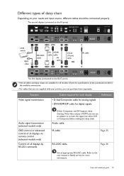
... by RS-232 commands D-Sub, Composite, and DVI support daisy chaining. If the video output is HDMI, you can use an adapter to the user manual or BenQ service for all models. Page 36 Use an appropriate RS-232C cable.
... by RS-232 commands D-Sub, Composite, and DVI support daisy chaining. If the video output is HDMI, you can use an adapter to the user manual or BenQ service for all models. Page 36 Use an appropriate RS-232C cable.

Installation Handbook
Page 35
... ID numbers have been set, you are ready to control all displays using the IR cables (purchased separately if not supplied). 2. Refer to the user manual of remote control. 5. Refer to Notes on using the remote control on each of the first display. 3. Connect the supplied IR extender to create an...
... ID numbers have been set, you are ready to control all displays using the IR cables (purchased separately if not supplied). 2. Refer to the user manual of remote control. 5. Refer to Notes on using the remote control on each of the first display. 3. Connect the supplied IR extender to create an...

Installation Handbook
Page 36
...1. Connect all displays using a RS-232C serial null modem cable (purchased separately if not supplied). 3. Management by receiving RS-232 commands from the BenQ local website) for the commands. Management by RS-232 commands: PL460/PH460/PL550/PH550 The video wall can be managed by LAN: PL460/PH460/PL550.../PH550 1. Refer to the user manual or BenQ service for each display. RS-232C cable • Use an appropriate RS-232C cable. Now the computer and all displays separately to a LAN...
...1. Connect all displays using a RS-232C serial null modem cable (purchased separately if not supplied). 3. Management by receiving RS-232 commands from the BenQ local website) for the commands. Management by RS-232 commands: PL460/PH460/PL550/PH550 The video wall can be managed by LAN: PL460/PH460/PL550.../PH550 1. Refer to the user manual or BenQ service for each display. RS-232C cable • Use an appropriate RS-232C cable. Now the computer and all displays separately to a LAN...
Installation Handbook
Page 37
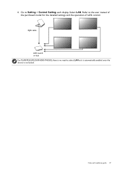
4. Refer to select LAN as it is automatically enabled once the device is no need to the user manual of the purchased model for the detailed settings and the operation of LAN control. RJ45 cable LAN switch or hub For PL490/PL552/PL553/PH5501/PH5502, there is connected. Go to Setting > Control Setting each display. Select LAN. Video wall installation guide 37
4. Refer to select LAN as it is automatically enabled once the device is no need to the user manual of the purchased model for the detailed settings and the operation of LAN control. RJ45 cable LAN switch or hub For PL490/PL552/PL553/PH5501/PH5502, there is connected. Go to Setting > Control Setting each display. Select LAN. Video wall installation guide 37
Installation Handbook
Page 38
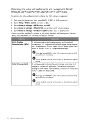
... as well as suggested. 1. Color Management Contact the BenQ customer service center for the software and the user manuals. and set Auto or delaying time. • You are provided with BenQ software to the user manual or BenQ service for more information. Refer to fully utilize the video...PH5502 To optimize the video wall performance, change the OSD settings as change display settings. Go to the user manual or BenQ service for more information. Software Description Multi-Display Administrator (MDA) A software program that enhances the image uniformity of a single or ...
... as well as suggested. 1. Color Management Contact the BenQ customer service center for the software and the user manuals. and set Auto or delaying time. • You are provided with BenQ software to the user manual or BenQ service for more information. Refer to fully utilize the video...PH5502 To optimize the video wall performance, change the OSD settings as change display settings. Go to the user manual or BenQ service for more information. Software Description Multi-Display Administrator (MDA) A software program that enhances the image uniformity of a single or ...

Installation Handbook
Page 42
... 42 Video wall installation guide There are two loops of screw holes (outer & inner), depend on the design of each model. (Please check the user manual for using loop information) • Outer loop: Big screw holes for M6 screw. • Inner loop: Small screw holes for M4 screw. 2. There... are two loops of screw holes (outer & inner), depend on the design of each model. (Please check the user manual for using loop information) • Outer loop: Big screw holes for M6 screw. • Inner loop: Small screw holes for M4 screw. 2. 1.
... 42 Video wall installation guide There are two loops of screw holes (outer & inner), depend on the design of each model. (Please check the user manual for using loop information) • Outer loop: Big screw holes for M6 screw. • Inner loop: Small screw holes for M4 screw. 2. There... are two loops of screw holes (outer & inner), depend on the design of each model. (Please check the user manual for using loop information) • Outer loop: Big screw holes for M6 screw. • Inner loop: Small screw holes for M4 screw. 2. 1.

Installation Handbook
Page 45
Setting the display position for special video wall layout If a special layout is requested, you will need an additional software and device (purchased separately) for more information. Video wall installation guide 45 Refer to the user manual of the purchased software for advanced settings.
Setting the display position for special video wall layout If a special layout is requested, you will need an additional software and device (purchased separately) for more information. Video wall installation guide 45 Refer to the user manual of the purchased software for advanced settings.

Installation Handbook
Page 65
... cable is switched on the back of the control panel (keypad) buttons and check if the OSD menu could be Contact the BenQ authorized service partner for damaged. switched on the selected input, connect the display with connected. The display is in the surroundings. display... to the properly. replacement. Poor quality cable is used for details. Possible causes Possible solutions The power cord is reduced. See the user manual for signal input. • Go to Picture > Noise Reduction. • Move the display to the default factory settings. If yes, ...
... cable is switched on the back of the control panel (keypad) buttons and check if the OSD menu could be Contact the BenQ authorized service partner for damaged. switched on the selected input, connect the display with connected. The display is in the surroundings. display... to the properly. replacement. Poor quality cable is used for details. Possible causes Possible solutions The power cord is reduced. See the user manual for signal input. • Go to Picture > Noise Reduction. • Move the display to the default factory settings. If yes, ...

Installation Handbook
Page 66
... connected properly. (If the input is D-Sub (VGA). Possible causes Possible solutions The video cable is not supported by your display. Refer to the user manual for stretched on the menu options. You are running at its native resolution. Possible causes Possible solutions Images from different input sources may be heard...
... connected properly. (If the input is D-Sub (VGA). Possible causes Possible solutions The video cable is not supported by your display. Refer to the user manual for stretched on the menu options. You are running at its native resolution. Possible causes Possible solutions Images from different input sources may be heard...

