User Guide
Page 17
...Guide Packing Qty. The motherboard delivers a host of the above items is damaged or missing, contact your motherboard package for buying an ASUS® Z9PA-D8 Series motherboard! 1.1 Welcome! Optional items PIKE 2208 PIKE 2108 PIKE 2008/IMR PIKE 2008 PIKE 9230 ASMB6-iKVM Description LSI 8-port ... 8-port SAS 6G RAID card LSI 8-port SAS 6G RAID card MARVELL 4-port SATA 6G RAID card Remote management solution provides KVM over IP solution ASUS Z9PA-D8 1-3 Standard Gift Box Pack 1 1 2 4 1 1 1 1 pc per carton Standard Bulk Pack 1 1 1 1 10 pcs per carton If any of new features and ...
...Guide Packing Qty. The motherboard delivers a host of the above items is damaged or missing, contact your motherboard package for buying an ASUS® Z9PA-D8 Series motherboard! 1.1 Welcome! Optional items PIKE 2208 PIKE 2108 PIKE 2008/IMR PIKE 2008 PIKE 9230 ASMB6-iKVM Description LSI 8-port ... 8-port SAS 6G RAID card LSI 8-port SAS 6G RAID card MARVELL 4-port SATA 6G RAID card Remote management solution provides KVM over IP solution ASUS Z9PA-D8 1-3 Standard Gift Box Pack 1 1 2 4 1 1 1 1 pc per carton Standard Bulk Pack 1 1 1 1 10 pcs per carton If any of new features and ...
User Guide
Page 19
... Command Queuing (NCQ), Power Management (PM) Implementation Algorithm, and Hot Swap. Additionally, get enhanced scalability, faster data retrieval, double the bandwidth of current bus systems. ASUS Z9PA-D8 1-5 The 4-channel DDR3 architecture also manages traffic with its complete backward compatibility to meet the higher bandwidth requirements of server and workstation applications. Serial ATA...
... Command Queuing (NCQ), Power Management (PM) Implementation Algorithm, and Hot Swap. Additionally, get enhanced scalability, faster data retrieval, double the bandwidth of current bus systems. ASUS Z9PA-D8 1-5 The 4-channel DDR3 architecture also manages traffic with its complete backward compatibility to meet the higher bandwidth requirements of server and workstation applications. Serial ATA...
User Guide
Page 22
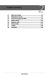
Chapter summary 2 2.1 Before you proceed 2-3 2.2 Motherboard overview 2-4 2.3 Central Processing Unit (CPU 2-8 2.4 System memory 2-13 2.5 Expansion slots 2-16 2.6 Onboard LEDs 2-21 2.7 Jumpers 2-26 2.8 Connectors 2-30 ASUS Z9PA-D8
Chapter summary 2 2.1 Before you proceed 2-3 2.2 Motherboard overview 2-4 2.3 Central Processing Unit (CPU 2-8 2.4 System memory 2-13 2.5 Expansion slots 2-16 2.6 Onboard LEDs 2-21 2.7 Jumpers 2-26 2.8 Connectors 2-30 ASUS Z9PA-D8
User Guide
Page 23
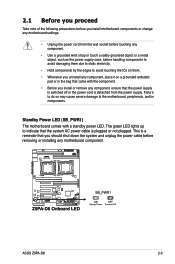
... or installing any component, place it on them due to static electricity. • Hold components by the edges to the motherboard, peripherals, and/or components. ASUS Z9PA-D8 2-3 The green LED lights up to indicate that the power supply is switched off or the power cord is plugged or not plugged. 2.1 Before you...
... or installing any component, place it on them due to static electricity. • Hold components by the edges to the motherboard, peripherals, and/or components. ASUS Z9PA-D8 2-3 The green LED lights up to indicate that the power supply is switched off or the power cord is plugged or not plugged. 2.1 Before you...
User Guide
Page 25
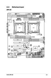
2.2.3 Motherboard layout Z9PA-D8 ASUS Z9PA-D8 2-5
2.2.3 Motherboard layout Z9PA-D8 ASUS Z9PA-D8 2-5
User Guide
Page 27
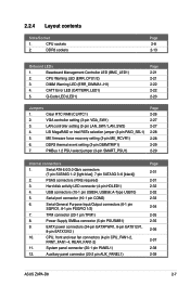
... firmware force recovery setting (3-pin ME_RCVR1) 6. Auxiliary panel connector (20-2 pin AUX_PANEL1) Page 2-31 2-31 2-32 2-32 2-33 2-34 2-35 2-35 2-36 2-37 2-38 2-39 ASUS Z9PA-D8 2-7 CPU sockets 2. CPU, front and rear fan connectors (4-pin CPU_FAN1-2, FRNT_FAN1-4, REAR_FAN1-2) 11.
... firmware force recovery setting (3-pin ME_RCVR1) 6. Auxiliary panel connector (20-2 pin AUX_PANEL1) Page 2-31 2-31 2-32 2-32 2-33 2-34 2-35 2-35 2-36 2-37 2-38 2-39 ASUS Z9PA-D8 2-7 CPU sockets 2. CPU, front and rear fan connectors (4-pin CPU_FAN1-2, FRNT_FAN1-4, REAR_FAN1-2) 11.
User Guide
Page 29
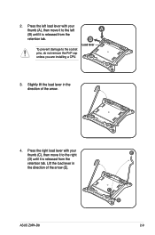
Load lever 3. A B To prevent damage to the left load lever with your thumb (A), then move it to the right (D) until it is released from the retention tab. ASUS Z9PA-D8 E C D 2-9 Press the left (B) until it to the socket pins, do not remove the PnP cap unless you are installing a CPU. Slightly lift the load lever in the direction of the arrow. 4. Press the right load lever with your thumb (C), then move it is released from the retention tab. Lift the load lever in the direction of the arrow (E). 2.
Load lever 3. A B To prevent damage to the left load lever with your thumb (A), then move it to the right (D) until it is released from the retention tab. ASUS Z9PA-D8 E C D 2-9 Press the left (B) until it to the socket pins, do not remove the PnP cap unless you are installing a CPU. Slightly lift the load lever in the direction of the arrow. 4. Press the right load lever with your thumb (C), then move it is released from the retention tab. Lift the load lever in the direction of the arrow (E). 2.

User Guide
Page 31
Push down the left load lever (L), and then insert the lever under the retention tab. K J 10. Push down the right load lever (J), ensuring that the edge of the load plate is fixed by the lever (K). 9. M L ASUS Z9PA-D8 2-11 Insert the right load lever under the retention tab (M). 8.
Push down the left load lever (L), and then insert the lever under the retention tab. K J 10. Push down the right load lever (J), ensuring that the edge of the load plate is fixed by the lever (K). 9. M L ASUS Z9PA-D8 2-11 Insert the right load lever under the retention tab (M). 8.
User Guide
Page 33
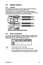
ASUS Z9PA-D8 2-13 DDR3 modules are developed for better performance with less power consumption. 2.4.2 Memory Configurations You may install 1GB, 2GB, 4GB, 8GB and 16GB* RDIMMs or ... four (for CPU1) and four (for latest update. • Install the DIMMs starting from the same vendor. For optimum compatibility, it is notched differently to ASUS Server AVL for CPU2) Double Data Rate 3 (DDR3) Dual Inline Memory Modules (DIMM) sockets. A DDR3 module has the same physical dimensions as a DDR2 DIMM but...
ASUS Z9PA-D8 2-13 DDR3 modules are developed for better performance with less power consumption. 2.4.2 Memory Configurations You may install 1GB, 2GB, 4GB, 8GB and 16GB* RDIMMs or ... four (for CPU1) and four (for latest update. • Install the DIMMs starting from the same vendor. For optimum compatibility, it is notched differently to ASUS Server AVL for CPU2) Double Data Rate 3 (DDR3) Dual Inline Memory Modules (DIMM) sockets. A DDR3 module has the same physical dimensions as a DDR2 DIMM but...
User Guide
Page 35
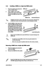
... a notch so that the notch on the DIMM matches the DIMM slot key on a single clip DIMM socket 1. Apply force to avoid damaging the DIMM. 3. ASUS Z9PA-D8 2-15 Align a DIMM on the socket such that it flips out with your fingers when pressing the retaining clips. The DIMM might get damaged when...
... a notch so that the notch on the DIMM matches the DIMM slot key on a single clip DIMM socket 1. Apply force to avoid damaging the DIMM. 3. ASUS Z9PA-D8 2-15 Align a DIMM on the socket such that it flips out with your fingers when pressing the retaining clips. The DIMM might get damaged when...
User Guide
Page 37
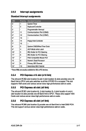
ASUS Z9PA-D8 2-17 Programmable Interrupt 3* 11 Communications Port (COM2) 4* 12 Communications Port (COM1) 5* 13 -- 6 14 Floppy Disk Controller 7* 15 -- 8 3 System CMOS/Real Time Clock 9* 4 ACPI Mode when ...
ASUS Z9PA-D8 2-17 Programmable Interrupt 3* 11 Communications Port (COM2) 4* 12 Communications Port (COM1) 5* 13 -- 6 14 Floppy Disk Controller 7* 15 -- 8 3 System CMOS/Real Time Clock 9* 4 ACPI Mode when ...

User Guide
Page 39
2.5.8 Installing an ASUS PIKE RAID card Follow the steps below to install an optional ASUS PIKE RAID card on the PIKE RAID card slot. Insert the PIKE RAID card into the PIKE RAID card slot. Ensure that it is completely seated on your motherboard. 1. Align the golden fingers of the PIKE RAID card with the PIKE RAID card slot. ASUS Z9PA-D8 2-19 Locate the PIKE RAID card slot on the motherboard. 2.
2.5.8 Installing an ASUS PIKE RAID card Follow the steps below to install an optional ASUS PIKE RAID card on the PIKE RAID card slot. Insert the PIKE RAID card into the PIKE RAID card slot. Ensure that it is completely seated on your motherboard. 1. Align the golden fingers of the PIKE RAID card with the PIKE RAID card slot. ASUS Z9PA-D8 2-19 Locate the PIKE RAID card slot on the motherboard. 2.

User Guide
Page 41
... The BMC LED blinks after system initiation finishes. • The heartbeat LED functions only when you install the ASUS ASMB6. • Everytime after the AC power is OFF, ASUS ASMB6 management device starts system initiation for the system to power up to wait for about 30 seconds for about... one (1) minute. When the PSU is plugged and the system is replugged, you have to indicate an impending failure of the corresponding CPU. ASUS Z9PA-D8 2-21
... The BMC LED blinks after system initiation finishes. • The heartbeat LED functions only when you install the ASUS ASMB6. • Everytime after the AC power is OFF, ASUS ASMB6 management device starts system initiation for the system to power up to wait for about 30 seconds for about... one (1) minute. When the PSU is plugged and the system is replugged, you have to indicate an impending failure of the corresponding CPU. ASUS Z9PA-D8 2-21

User Guide
Page 43
ASUS Z9PA-D8 2-23 Refer to the Q-Code table below for more details. Q-Code LED (LED1) The Q-Code LED provides you a 2-digit display that shows the system status. 5.
ASUS Z9PA-D8 2-23 Refer to the Q-Code table below for more details. Q-Code LED (LED1) The Q-Code LED provides you a 2-digit display that shows the system status. 5.

User Guide
Page 45
... ME event for Node Manager ME event for Node Manager ME event for Node Manager ME event for Node Manager ME event for Node Manager ASUS Z9PA-D8 2-25 BDS started Connect device event PCI Bus Enumeration. SB run-time init. SB Init. CSM Init. IDE, AHCI Init.
... ME event for Node Manager ME event for Node Manager ME event for Node Manager ME event for Node Manager ME event for Node Manager ASUS Z9PA-D8 2-25 BDS started Connect device event PCI Bus Enumeration. SB run-time init. SB Init. CSM Init. IDE, AHCI Init.
User Guide
Page 47
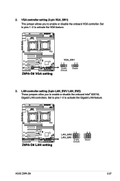
Set to pins 1-2 to activate the VGA feature. 3. 2. Set to pins 1-2 to activate the Gigabit LAN feature. LAN controller setting (3-pin LAN_SW1/ LAN_SW2) These jumpers allow you to enable or disable the onboard Intel® 82574L Gigabit LAN controllers. VGA controller setting (3-pin VGA_SW1) This jumper allows you to enable or disable the onboard VGA controller. ASUS Z9PA-D8 2-27
Set to pins 1-2 to activate the VGA feature. 3. 2. Set to pins 1-2 to activate the Gigabit LAN feature. LAN controller setting (3-pin LAN_SW1/ LAN_SW2) These jumpers allow you to enable or disable the onboard Intel® 82574L Gigabit LAN controllers. VGA controller setting (3-pin VGA_SW1) This jumper allows you to enable or disable the onboard VGA controller. ASUS Z9PA-D8 2-27
User Guide
Page 49
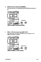
DDR3 thermal event setting (3-pin DIMMTRIP1) This jumper allows you to select PSU PMBus version, Set to pins 1-2 for Others. PMBus 1.2 PSU select jumper (3-pin SMART_PSU1) This jumper allows you to pins 2-3 for PMBus, set to enable/disable DDR3 DIMM thermal sensing event pin. 7. ASUS Z9PA-D8 2-29 6.
DDR3 thermal event setting (3-pin DIMMTRIP1) This jumper allows you to select PSU PMBus version, Set to pins 1-2 for Others. PMBus 1.2 PSU select jumper (3-pin SMART_PSU1) This jumper allows you to pins 2-3 for PMBus, set to enable/disable DDR3 DIMM thermal sensing event pin. 7. ASUS Z9PA-D8 2-29 6.
User Guide
Page 51
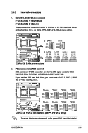
... and optical disc drives via Serial ATA 6.0Gb/s or 3.0 Gb/s signal cables. 2. The actual data transfer rate depends on the speed of data transfer rate. ASUS Z9PA-D8 2-31 PSAS connectors (PIKE required) SAS connector - If you installed SAS hard disk drives, you can create a RAID 0, RAID 1, RAID 10, or RAID 5 configuration. Serial...
... and optical disc drives via Serial ATA 6.0Gb/s or 3.0 Gb/s signal cables. 2. The actual data transfer rate depends on the speed of data transfer rate. ASUS Z9PA-D8 2-31 PSAS connectors (PIKE required) SAS connector - If you installed SAS hard disk drives, you can create a RAID 0, RAID 1, RAID 10, or RAID 5 configuration. Serial...
User Guide
Page 53
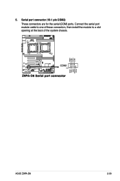
Serial port connector (10-1 pin COM2) These connectors are for the serial (COM) ports. ASUS Z9PA-D8 2-33 Connect the serial port module cable to one of these connectors, then install the module to a slot opening at the back of the system chassis. 5.
Serial port connector (10-1 pin COM2) These connectors are for the serial (COM) ports. ASUS Z9PA-D8 2-33 Connect the serial port module cable to one of these connectors, then install the module to a slot opening at the back of the system chassis. 5.
User Guide
Page 55
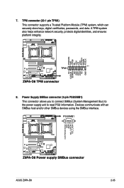
Devices communicate with an SMBus host and/or other SMBus devices using the SMBus interface. A TPM system also helps enhance network security, protects digital identities, and ensures platform integrity. 8. ASUS Z9PA-D8 2-35 TPM connector (20-1 pin TPM1) This connector supports a Trusted Platform Module (TPM) system, which can securely store keys, digital certificates, passwords, and data. Power Supply SMBus connector (5-pin PSUSMB1) This connector allows you to connect SMBus (System Management Bus) to the power supply unit to read PSU information. 7.
Devices communicate with an SMBus host and/or other SMBus devices using the SMBus interface. A TPM system also helps enhance network security, protects digital identities, and ensures platform integrity. 8. ASUS Z9PA-D8 2-35 TPM connector (20-1 pin TPM1) This connector supports a Trusted Platform Module (TPM) system, which can securely store keys, digital certificates, passwords, and data. Power Supply SMBus connector (5-pin PSUSMB1) This connector allows you to connect SMBus (System Management Bus) to the power supply unit to read PSU information. 7.


