

User Guide
Page 1
Z97-E Motherboard
Z97-E Motherboard

User Guide
Page 3
Contents Safety information...vi About this guide...vii Z97-E specifications summary ix Package contents...xiii Installation tools and components xiv Chapter 1: Product Introduction 1.1 Special features 1-1 1.1.1 Product highlights 1-1 1.1.2 5X Protection 1-2 1.1.3 ASUS Exclusive Features 1-2 1.2 Motherboard overview 1-3 1.2.1 Before you proceed 1-3 1.2.2 Motherboard layout 1-4 1.2.3 Central Processing Unit (CPU 1-6 1.2.4 System memory 1-7 1.2.5 Expansion slots 1-9 1.2.6 Jumpers 1-11 1.2.7 Onboard LEDs 1-12 1.2.8 Internal connectors 1-12...
Contents Safety information...vi About this guide...vii Z97-E specifications summary ix Package contents...xiii Installation tools and components xiv Chapter 1: Product Introduction 1.1 Special features 1-1 1.1.1 Product highlights 1-1 1.1.2 5X Protection 1-2 1.1.3 ASUS Exclusive Features 1-2 1.2 Motherboard overview 1-3 1.2.1 Before you proceed 1-3 1.2.2 Motherboard layout 1-4 1.2.3 Central Processing Unit (CPU 1-6 1.2.4 System memory 1-7 1.2.5 Expansion slots 1-9 1.2.6 Jumpers 1-11 1.2.7 Onboard LEDs 1-12 1.2.8 Internal connectors 1-12...

User Guide
Page 6
...removing signal cables from connectors, slots, sockets and circuitry. • Avoid dust, humidity, and temperature extremes. Operation safety • Before installing the motherboard and adding devices on a stable surface. • If you are using, contact your local power company. • If the power supply is...place the product in your dealer immediately. • To avoid short circuits, keep paper clips, screws, and staples away from the motherboard, ensure that the power cables for the devices are unplugged before the signal cables are not sure about the voltage of the electrical...
...removing signal cables from connectors, slots, sockets and circuitry. • Avoid dust, humidity, and temperature extremes. Operation safety • Before installing the motherboard and adding devices on a stable surface. • If you are using, contact your local power company. • If the power supply is...place the product in your dealer immediately. • To avoid short circuits, keep paper clips, screws, and staples away from the motherboard, ensure that the power cables for the devices are unplugged before the signal cables are not sure about the voltage of the electrical...

User Guide
Page 7
...software. 5. Optional documentation Your product package may have to perform when installing system components. 3. ASUS website The ASUS website (www.asus.com) provides updated information on the motherboard. 2. About this guide is organized This guide contains the following sources for additional information and for...the information you have been added by your dealer. Chapter 4: Software support This chapter describes the contents of the motherboard and the new technology it supports. Where to find more information Refer to change system settings through the BIOS Setup ...
...software. 5. Optional documentation Your product package may have to perform when installing system components. 3. ASUS website The ASUS website (www.asus.com) provides updated information on the motherboard. 2. About this guide is organized This guide contains the following sources for additional information and for...the information you have been added by your dealer. Chapter 4: Software support This chapter describes the contents of the motherboard and the new technology it supports. Where to find more information Refer to change system settings through the BIOS Setup ...
User Guide
Page 13
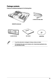
Actual product specifications may vary with different models. xiii Package contents Check your motherboard package for the following items ASUS Z97-E motherboard 2 x Serial ATA 6 Gb/s cables 1 x ASUS I/O Shield User Manual User manual Support DVD • If any of the above items is damaged or missing, contact your retailer. • The illustrated items above are for reference only.
Actual product specifications may vary with different models. xiii Package contents Check your motherboard package for the following items ASUS Z97-E motherboard 2 x Serial ATA 6 Gb/s cables 1 x ASUS I/O Shield User Manual User manual Support DVD • If any of the above items is damaged or missing, contact your retailer. • The illustrated items above are for reference only.

User Guide
Page 14
Installation tools and components Intel® LGA1150 compatible CPU Fan Intel® LGA1150 CPU PC chassis SATA hard disk drive Philips (cross) screwdriver Power supply unit 1 bag of screws DIMM SATA optical disc drive (optional) Graphics card The tools and components in the table above are not included in the motherboard package. xiv
Installation tools and components Intel® LGA1150 compatible CPU Fan Intel® LGA1150 CPU PC chassis SATA hard disk drive Philips (cross) screwdriver Power supply unit 1 bag of screws DIMM SATA optical disc drive (optional) Graphics card The tools and components in the table above are not included in the motherboard package. xiv

User Guide
Page 15
...ASUS Z97-E 1-1 Chapter 1: Product Introduction Product introduction 1.1 Special features 1 1.1.1 Product highlights LGA1150 socket for the 4th, New 4th & 5th Generation Intel® Core™ i7/Intel® Core™ i5/Intel® Core™ i3, Pentium® and Celeron® processors This motherboard... with its GPU, dual-channel DDR3 memory slots and PCI Express 2.0/3.0 expansion slots. The motherboard features the most powerful Intel® Z97 platform that optimizes PCIe allocation in the LGA1150 package. Intel® Desktop Responsiveness Technologies Intel Desktop...
...ASUS Z97-E 1-1 Chapter 1: Product Introduction Product introduction 1.1 Special features 1 1.1.1 Product highlights LGA1150 socket for the 4th, New 4th & 5th Generation Intel® Core™ i7/Intel® Core™ i5/Intel® Core™ i3, Pentium® and Celeron® processors This motherboard... with its GPU, dual-channel DDR3 memory slots and PCI Express 2.0/3.0 expansion slots. The motherboard features the most powerful Intel® Z97 platform that optimizes PCIe allocation in the LGA1150 package. Intel® Desktop Responsiveness Technologies Intel Desktop...

User Guide
Page 16
..., multimedia and Internet applications. C.)*/2666(O.C.)*/2600(O.C.)*/2400(O.C.)*/2250(O.C.)*/2200(O.C.)*/2133(O.C.)*/2 000(O.C.)*/1866(O.C.)*/ 1600 / 1333 MHz Support The motherboard supports the dual-channel DDR3 memory that has exceptional clarity and fidelity. It lets you to ten times faster than ...USB 2.0. 1.1.2 5X Protection 5X PROTECTION ASUS motherboards guard your hard drive into a private cloud, removing worries about storage limits. With HomeCloud, your PC becomes the gateway to 10 Gb/s. M.2 Support This motherboard features the M.2 slot, which shares bandwidth with...
..., multimedia and Internet applications. C.)*/2666(O.C.)*/2600(O.C.)*/2400(O.C.)*/2250(O.C.)*/2200(O.C.)*/2133(O.C.)*/2 000(O.C.)*/1866(O.C.)*/ 1600 / 1333 MHz Support The motherboard supports the dual-channel DDR3 memory that has exceptional clarity and fidelity. It lets you to ten times faster than ...USB 2.0. 1.1.2 5X Protection 5X PROTECTION ASUS motherboards guard your hard drive into a private cloud, removing worries about storage limits. With HomeCloud, your PC becomes the gateway to 10 Gb/s. M.2 Support This motherboard features the M.2 slot, which shares bandwidth with...
User Guide
Page 17
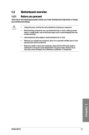
Chapter 1 ASUS Z97-E 1-3 Failure to do so may cause severe damage to avoid touching the ICs on them. • Whenever you uninstall... is switched off or the power cord is detached from the power supply. 1.2 Motherboard overview 1.2.1 Before you proceed Take note of the following precautions before you install motherboard components or change any motherboard settings. • Unplug the power cord from the wall socket before touching any ... supply case, to avoid damaging them due to static electricity. • Hold components by the edges to the motherboard, peripherals, or components.
Chapter 1 ASUS Z97-E 1-3 Failure to do so may cause severe damage to avoid touching the ICs on them. • Whenever you uninstall... is switched off or the power cord is detached from the power supply. 1.2 Motherboard overview 1.2.1 Before you proceed Take note of the following precautions before you install motherboard components or change any motherboard settings. • Unplug the power cord from the wall socket before touching any ... supply case, to avoid damaging them due to static electricity. • Hold components by the edges to the motherboard, peripherals, or components.
User Guide
Page 18
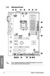
Chapter 1 1-4 Chapter 1: Product introduction 1.2.2 Motherboard layout 1 2 3 1 21.8cm(8.6in) 4 5 6 KBMS_USB78 EATX12V CPU_FAN CHA_FAN2 DIGI +VRM DVI VGA DDR3 DIMM_A1 (64bit, 240-pin module) DDR3 DIMM_A2 (64bit, 240...CHA_FAN3 1 2 2 30.5cm(12.0in) USB3_12 EATXPWR SATAEXPRESS SATA6G_6 SATA6G_5 AUDIO Intel® I218-V ASM 1083 CHA_FAN1 PCIEX1_1 Z97-E PCIEX16_1 PCIEX1_2 PCIEX1_3 BATTERY M.2(SOCKET3) 7 Intel® Z97 Super I/O ALC 892 SPDIF_OUT AAFP PCIEX16_2 PCI1 64Mb BIOS PCI2 COM TPM SB_PWR CLRTC USB910 USB1112 USB1314 PANEL SATA6G_1 SATA6G_3 SATA6G_2 SATA6G_4...
Chapter 1 1-4 Chapter 1: Product introduction 1.2.2 Motherboard layout 1 2 3 1 21.8cm(8.6in) 4 5 6 KBMS_USB78 EATX12V CPU_FAN CHA_FAN2 DIGI +VRM DVI VGA DDR3 DIMM_A1 (64bit, 240-pin module) DDR3 DIMM_A2 (64bit, 240...CHA_FAN3 1 2 2 30.5cm(12.0in) USB3_12 EATXPWR SATAEXPRESS SATA6G_6 SATA6G_5 AUDIO Intel® I218-V ASM 1083 CHA_FAN1 PCIEX1_1 Z97-E PCIEX16_1 PCIEX1_2 PCIEX1_3 BATTERY M.2(SOCKET3) 7 Intel® Z97 Super I/O ALC 892 SPDIF_OUT AAFP PCIEX16_2 PCI1 64Mb BIOS PCI2 COM TPM SB_PWR CLRTC USB910 USB1112 USB1314 PANEL SATA6G_1 SATA6G_3 SATA6G_2 SATA6G_4...
User Guide
Page 20
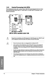
...see any damage to the socket contacts resulting from incorrect CPU installation/removal, or misplacement/loss/incorrect removal of the PnP cap. Z97-E Z97-E CPU socket LGA1150 Ensure that the PnP cap is missing, or if you install the correct CPU designed for LGA1150 socket only... Intel® Core™ i5 / Intel® Core™ i3, Pentium®, and Celeron® processors. ASUS will process Return Merchandise Authorization (RMA) requests only if the motherboard comes with a surface mount LGA1150 socket designed for LGA155 and LGA1156 sockets on the LGA1150 socket. • Ensure that...
...see any damage to the socket contacts resulting from incorrect CPU installation/removal, or misplacement/loss/incorrect removal of the PnP cap. Z97-E Z97-E CPU socket LGA1150 Ensure that the PnP cap is missing, or if you install the correct CPU designed for LGA1150 socket only... Intel® Core™ i5 / Intel® Core™ i3, Pentium®, and Celeron® processors. ASUS will process Return Merchandise Authorization (RMA) requests only if the motherboard comes with a surface mount LGA1150 socket designed for LGA155 and LGA1156 sockets on the LGA1150 socket. • Ensure that...
User Guide
Page 21
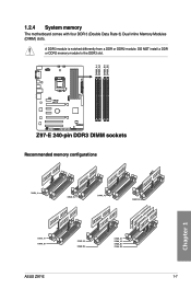
DO NOT install a DDR or DDR2 memory module to the DDR3 slot. Z97-E Z97-E 240-pin DDR3 DIMM sockets Recommended memory configurations Chapter 1 ASUS Z97-E 1-7 DIMM_A1 DIMM_A2 DIMM_B1 DIMM_B2 1.2.4 System memory The motherboard comes with four DDR 3 (Double Data Rate 3) Dual Inline Memory Modules (DIMM) slots. A DDR3 module is notched differently from a DDR or DDR2 module.
DO NOT install a DDR or DDR2 memory module to the DDR3 slot. Z97-E Z97-E 240-pin DDR3 DIMM sockets Recommended memory configurations Chapter 1 ASUS Z97-E 1-7 DIMM_A1 DIMM_A2 DIMM_B1 DIMM_B2 1.2.4 System memory The motherboard comes with four DDR 3 (Double Data Rate 3) Dual Inline Memory Modules (DIMM) slots. A DDR3 module is notched differently from a DDR or DDR2 module.

User Guide
Page 22
...overclocking condition. • Memory modules with the same CAS Latency. Check with the vendor to get the correct memory modules. • ASUS exclusively provides hyper DIMM support function. • Hyper DIMM support is subject to the Microsoft® support site at a lower frequency ...than 2133MHz and their corresponding timing or the loaded XMP profile is dependent on the motherboard, the actual usable memory for the dual-channel configuration. Chapter 1 1-8 Chapter 1: Product introduction Any excess memory from the same vendor...
...overclocking condition. • Memory modules with the same CAS Latency. Check with the vendor to get the correct memory modules. • ASUS exclusively provides hyper DIMM support function. • Hyper DIMM support is subject to the Microsoft® support site at a lower frequency ...than 2133MHz and their corresponding timing or the loaded XMP profile is dependent on the motherboard, the actual usable memory for the dual-channel configuration. Chapter 1 1-8 Chapter 1: Product introduction Any excess memory from the same vendor...
User Guide
Page 23
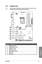
PCIEX1_1 Z97-E PCIEX16_1 PCIEX1_2 PCIEX1_3 PCIEX16_2 PCI1 PCI2 Slot No. 1 2 3 4 5 6 7 Slot Description PCIe 2.0 x1_1 slot PCIe 3.0/2.0 x16_1 slot PCIe 2.0 x1_2 slot PCIe 2.0 x1_3 slot PCIe 3.0/2.0 x16_2 slot PCI_1 slot PCI_2 slot ASUS Z97-E 1-9 Chapter 1 1.2.5 Expansion slots Unplug the power cord before adding or removing expansion cards. Failure to do so may cause you physical injury and damage motherboard components.
PCIEX1_1 Z97-E PCIEX16_1 PCIEX1_2 PCIEX1_3 PCIEX16_2 PCI1 PCI2 Slot No. 1 2 3 4 5 6 7 Slot Description PCIe 2.0 x1_1 slot PCIe 3.0/2.0 x16_1 slot PCIe 2.0 x1_2 slot PCIe 2.0 x1_3 slot PCIe 3.0/2.0 x16_2 slot PCI_1 slot PCI_2 slot ASUS Z97-E 1-9 Chapter 1 1.2.5 Expansion slots Unplug the power cord before adding or removing expansion cards. Failure to do so may cause you physical injury and damage motherboard components.

User Guide
Page 24
... to get better performance. • We recommend that you provide sufficient power when running SLI™ and CrossFireX™. • Connect a chassis fan to the motherboard connector labeled CHA_FAN1/2/3 when using multiple graphics cards for this motherboard A B C PCIEX1_1 shared - - Intel® xHCI - - - shared - - - - - HD Audio - - -
... to get better performance. • We recommend that you provide sufficient power when running SLI™ and CrossFireX™. • Connect a chassis fan to the motherboard connector labeled CHA_FAN1/2/3 when using multiple graphics cards for this motherboard A B C PCIEX1_1 shared - - Intel® xHCI - - - shared - - - - - HD Audio - - -

User Guide
Page 26
... is purchased separately. 1-12 Chapter 1: Product introduction Chapter 1 The illustration below shows the location of the onboard LED. Z97-E SB_PWR ON OFF Standby Power Powered Off Z97-E Standby power LED 1.2.8 Internal connectors 1. TPM connector (20-1 pin TPM) This connector supports a Trusted Platform Module (... PCIRST# LFRAME# LCLK Z97-E PIN 1 TPM NC CLKRUN# SERIRQ NC GND LAD1 LAD2 NC GND Z97-E TPM connector The TPM module is a reminder that the system is ON, in sleep mode, or in any motherboard component. Standby Power LED The motherboard comes with a standby ...
... is purchased separately. 1-12 Chapter 1: Product introduction Chapter 1 The illustration below shows the location of the onboard LED. Z97-E SB_PWR ON OFF Standby Power Powered Off Z97-E Standby power LED 1.2.8 Internal connectors 1. TPM connector (20-1 pin TPM) This connector supports a Trusted Platform Module (... PCIRST# LFRAME# LCLK Z97-E PIN 1 TPM NC CLKRUN# SERIRQ NC GND LAD1 LAD2 NC GND Z97-E TPM connector The TPM module is a reminder that the system is ON, in sleep mode, or in any motherboard component. Standby Power LED The motherboard comes with a standby ...
User Guide
Page 28
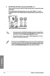
...you can create a RAID 0, 1, 5, and 10 configuration with the Intel® Rapid Storage Technology through the onboard Intel® Z97 chipset. Refer to [AHCI Mode] by default. When you use both connectors, the system automatically detects the devices connected to these connectors... GND GND RSATA_RXP4 RSATA_RXN4 GND RSATA_TXN4 RSATA_TXP4 GND 3. Intel® Z97 Serial ATA 6 Gb/s connectors (7-pin SATA6G_1~4 ) These connectors connect to M.2 Socket 3 than SATAEXPRESS interface. SATA6G_1 SATA6G_3 Z97-E SATA6G_2 SATA6G_4 Z97-E Intel® SATA 6 Gb/s connectors • These connectors ...
...you can create a RAID 0, 1, 5, and 10 configuration with the Intel® Rapid Storage Technology through the onboard Intel® Z97 chipset. Refer to [AHCI Mode] by default. When you use both connectors, the system automatically detects the devices connected to these connectors... GND GND RSATA_RXP4 RSATA_RXN4 GND RSATA_TXN4 RSATA_TXP4 GND 3. Intel® Z97 Serial ATA 6 Gb/s connectors (7-pin SATA6G_1~4 ) These connectors connect to M.2 Socket 3 than SATAEXPRESS interface. SATA6G_1 SATA6G_3 Z97-E SATA6G_2 SATA6G_4 Z97-E Intel® SATA 6 Gb/s connectors • These connectors ...
User Guide
Page 29
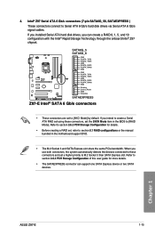
...create a RAID 0, 1, 5, and 10 configuration with the Intel® Rapid Storage Technology through the onboard Intel® Z97 chipset. If you intend to create a Serial ATA RAID set using these connectors and set , refer to section 5.1 ...RSATA_TXP6 RSATA_TXN6 GND RSATA_RXP6 RSATA_RXN6 GND Floating Device_Reset GND Detection SATAEXPRESS Z97-E Intel® SATA 6 Gb/s connectors • These connectors are set the SATA Mode item in the motherboard support DVD. • The M.2 Socket 3 and SATA Express...Gb/s hard disk drives via Serial ATA 6 Gb/s signal cables. Chapter 1 ASUS Z97-E 1-15
...create a RAID 0, 1, 5, and 10 configuration with the Intel® Rapid Storage Technology through the onboard Intel® Z97 chipset. If you intend to create a Serial ATA RAID set using these connectors and set , refer to section 5.1 ...RSATA_TXP6 RSATA_TXN6 GND RSATA_RXP6 RSATA_RXN6 GND Floating Device_Reset GND Detection SATAEXPRESS Z97-E Intel® SATA 6 Gb/s connectors • These connectors are set the SATA Mode item in the motherboard support DVD. • The M.2 Socket 3 and SATA Express...Gb/s hard disk drives via Serial ATA 6 Gb/s signal cables. Chapter 1 ASUS Z97-E 1-15

User Guide
Page 30
...one end of the front panel audio I /O module that you connect a high-definition front panel audio module to this connector to avail of the motherboard's high-definition audio capability. • If you want to connect a high-definition or an AC'97 front panel audio module to this connector, set... in the BIOS setup to this connector, then install the module to a slot opening at the back of the system chassis. +5V SPDIFOUT GND Z97-E PIN 1 SPDIF_OUT Z97-E Digital audio connector The S/PDIF module is for a chassis-mounted front panel audio I /O module cable to [HD] or [AC97]. 1-16 Chapter ...
...one end of the front panel audio I /O module that you connect a high-definition front panel audio module to this connector to avail of the motherboard's high-definition audio capability. • If you want to connect a high-definition or an AC'97 front panel audio module to this connector, set... in the BIOS setup to this connector, then install the module to a slot opening at the back of the system chassis. +5V SPDIFOUT GND Z97-E PIN 1 SPDIF_OUT Z97-E Digital audio connector The S/PDIF module is for a chassis-mounted front panel audio I /O module cable to [HD] or [AC97]. 1-16 Chapter ...
User Guide
Page 31
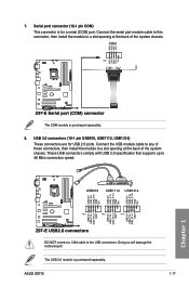
...TXD GND RTS RI 7. USB 2.0 connectors (10-1 pin USB910, USB1112, USB1314) These connectors are for a serial (COM) port. ASUS Z97-E 1-17 COM PIN 1 Z97-E Z97-E Serial port (COM) connector The COM module is purchased separately. The USB 2.0 module is purchased separately. 8. These USB connectors comply ...1 USB+5V USB_P10USB_P10+ GND USB+5V USB_P12USB_P12+ GND USB+5V USB_P14USB_P14+ GND Z97-E USB2.0 connectors DO NOT connect a 1394 cable to 48 Mb/s connection speed. Doing so will damage the motherboard! Connect the USB module cable to any of these connectors, then install the ...
...TXD GND RTS RI 7. USB 2.0 connectors (10-1 pin USB910, USB1112, USB1314) These connectors are for a serial (COM) port. ASUS Z97-E 1-17 COM PIN 1 Z97-E Z97-E Serial port (COM) connector The COM module is purchased separately. The USB 2.0 module is purchased separately. 8. These USB connectors comply ...1 USB+5V USB_P10USB_P10+ GND USB+5V USB_P12USB_P12+ GND USB+5V USB_P14USB_P14+ GND Z97-E USB2.0 connectors DO NOT connect a 1394 cable to 48 Mb/s connection speed. Doing so will damage the motherboard! Connect the USB module cable to any of these connectors, then install the ...


