
User Guide
Page 3
Contents Safety information...v About this guide...vi X99-PRO/USB 3.1 specifications summary viii Package contents...xiv Installation tools and components xv Chapter 1: Product Introduction 1.1 Special features 1-1... 2-6 2.1.5 ATX Power connection 2-7 2.1.6 SATA device connection 2-8 2.1.7 Front I/O Connector 2-9 2.1.8 Expansion Card installation 2-10 2.1.9 Wi-Fi antenna installation 2-12 2.2 BIOS update utility 2-13 2.3 Motherboard rear and audio connections 2-14 2.3.1 Rear I/O connection 2-14 2.3.2 Audio I/O connections 2-16 2.4 Starting up for the first time ...
Contents Safety information...v About this guide...vi X99-PRO/USB 3.1 specifications summary viii Package contents...xiv Installation tools and components xv Chapter 1: Product Introduction 1.1 Special features 1-1... 2-6 2.1.5 ATX Power connection 2-7 2.1.6 SATA device connection 2-8 2.1.7 Front I/O Connector 2-9 2.1.8 Expansion Card installation 2-10 2.1.9 Wi-Fi antenna installation 2-12 2.2 BIOS update utility 2-13 2.3 Motherboard rear and audio connections 2-14 2.3.1 Rear I/O connection 2-14 2.3.2 Audio I/O connections 2-16 2.4 Starting up for the first time ...

User Guide
Page 4
... 3.6.4 System Agent Configuration 3-38 3.6.5 USB Configuration 3-39 3.6.6 Platform Misc Configuration 3-41 3.6.7 Onboard Devices Configuration 3-42 3.6.8 APM Configuration 3-44 3.6.9 Network Stack Configuration 3-45 3.7 Monitor menu 3-46 3.8 Boot menu 3-51 3.9 Tool menu 3-57 3.9.1 ASUS EZ Flash 2 Utility 3-57 3.9.2 ASUS O.C. Profile 3-58 3.9.3 ASUS DRAM SPD Information 3-59 3.10 Exit menu 3-60 3.11 Updating BIOS 3-61 3.11.1 EZ Update...
... 3.6.4 System Agent Configuration 3-38 3.6.5 USB Configuration 3-39 3.6.6 Platform Misc Configuration 3-41 3.6.7 Onboard Devices Configuration 3-42 3.6.8 APM Configuration 3-44 3.6.9 Network Stack Configuration 3-45 3.7 Monitor menu 3-46 3.8 Boot menu 3-51 3.9 Tool menu 3-57 3.9.1 ASUS EZ Flash 2 Utility 3-57 3.9.2 ASUS O.C. Profile 3-58 3.9.3 ASUS DRAM SPD Information 3-59 3.10 Exit menu 3-60 3.11 Updating BIOS 3-61 3.11.1 EZ Update...

User Guide
Page 6
.... Chapter 2: Basic installation This chapter lists the hardware setup procedures that may have to change system settings through the BIOS Setup menus. About this guide is organized This guide contains the following sources for additional information and for product and software... guide This user guide contains the information you have been added by your dealer. ASUS website The ASUS website (www.asus.com) provides updated information on the motherboard. 2. Chapter 3: BIOS setup This chapter tells how to perform when installing system components. 3. Optional documentation Your...
.... Chapter 2: Basic installation This chapter lists the hardware setup procedures that may have to change system settings through the BIOS Setup menus. About this guide is organized This guide contains the following sources for additional information and for product and software... guide This user guide contains the information you have been added by your dealer. ASUS website The ASUS website (www.asus.com) provides updated information on the motherboard. 2. Chapter 3: BIOS setup This chapter tells how to perform when installing system components. 3. Optional documentation Your...
User Guide
Page 10
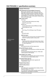
... with up to 32 Gb/s data transfer speeds for M.2 - Whole system optimization with ThunderboltEX II series Powerful Home Server ASUS HomeCloud Server Wi-Fi GO! - Auto Tuning, TPU, GPU Boost, 2-level TPU switch EPU - Featuring automatic system performance...!, Remote Desktop, Remote Keyboard & Mouse, File Transfer - ASUS CPU power utility DRAM Power - Superb memory O.C. capability under full load by Dual Intelligent Processors 5 - UEFI BIOS - X99-PRO/USB 3.1 specifications summary ASUS Exclusive Features Flagship Performance 5-Way Optimization by minimizing the coupling ...
... with up to 32 Gb/s data transfer speeds for M.2 - Whole system optimization with ThunderboltEX II series Powerful Home Server ASUS HomeCloud Server Wi-Fi GO! - Auto Tuning, TPU, GPU Boost, 2-level TPU switch EPU - Featuring automatic system performance...!, Remote Desktop, Remote Keyboard & Mouse, File Transfer - ASUS CPU power utility DRAM Power - Superb memory O.C. capability under full load by Dual Intelligent Processors 5 - UEFI BIOS - X99-PRO/USB 3.1 specifications summary ASUS Exclusive Features Flagship Performance 5-Way Optimization by minimizing the coupling ...
User Guide
Page 11
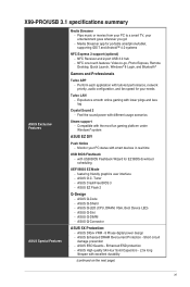
... in real time USB BIOS Flashback - ASUS CrashFree BIOS 3 - Experience smooth online gaming with the most fun gaming platform under Windows® system ASUS EZ DIY Push Notice - ASUS Q-Connector ASUS 5X Protection: - ASUS DIGI+ VRM - 8 Phase digital power design - ASUS ESD Guards - Media Streamer app for EZ BIOS download scheduling UEFI BIOS EZ Mode - X99-PRO/USB 3.1 specifications summary ASUS Exclusive Features ASUS Special Features...
... in real time USB BIOS Flashback - ASUS CrashFree BIOS 3 - Experience smooth online gaming with the most fun gaming platform under Windows® system ASUS EZ DIY Push Notice - ASUS Q-Connector ASUS 5X Protection: - ASUS DIGI+ VRM - 8 Phase digital power design - ASUS ESD Guards - Media Streamer app for EZ BIOS download scheduling UEFI BIOS EZ Mode - X99-PRO/USB 3.1 specifications summary ASUS Exclusive Features ASUS Special Features...
User Guide
Page 12
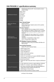
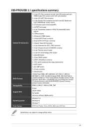
...X99-PRO/USB 3.1 specifications summary ASUS Special Features ASUS Quiet Thermal Solution ASUS Exclusive Overclocking Features Rear Panel I/O Ports Internal I /O - 3x more durable corrosionresistant coating USB 3.1 Boost USB Charger+ Ai Charger+ Disk Unlocker Ai Suite 3 MemOK! ASUS Fan Xpert 3 - Overclocking Protection - ASUS... ASUS Wi-Fi GO! ASUS C.P.R. (CPU Parameter Recall) 1 x BIOS Flashback button 1 x Optical S/PDIF Out port 1 x Intel® LAN (RJ45) port 2 x USB 3.1/3.0/2.0 ports (teal blue) 4 x USB 3.0/2.0 ports (blue) 4 x USB 2.0/1.1 ports (bottom port supports USB BIOS ...
...X99-PRO/USB 3.1 specifications summary ASUS Special Features ASUS Quiet Thermal Solution ASUS Exclusive Overclocking Features Rear Panel I/O Ports Internal I /O - 3x more durable corrosionresistant coating USB 3.1 Boost USB Charger+ Ai Charger+ Disk Unlocker Ai Suite 3 MemOK! ASUS Fan Xpert 3 - Overclocking Protection - ASUS... ASUS Wi-Fi GO! ASUS C.P.R. (CPU Parameter Recall) 1 x BIOS Flashback button 1 x Optical S/PDIF Out port 1 x Intel® LAN (RJ45) port 2 x USB 3.1/3.0/2.0 ports (teal blue) 4 x USB 3.0/2.0 ports (blue) 4 x USB 2.0/1.1 ports (bottom port supports USB BIOS ...
User Guide
Page 13
... x EZ XMP switch 1 x Power-on button 1 x Reset button 128 Mb Flash ROM, UEFI AMI BIOS, PnP, DMI 2.7, WfM 2.0, SM BIOS 2.7, ACPI 5.0, Multi-language BIOS, ASUS EZ Flash 2, CrashFree BIOS 3, F11 EZ Tuning Wizard, F6 Qfan Control, F3 My Favorites, Quick Note, Last Modified Log, F12 ... Drivers ASUS Utilities EZ Update Anti-virus software (OEM version) Windows® 8.1 Windows® 8 Windows® 7 ATX Form Factor, 12 in . (30.5 cm x 24.4 cm) Specifications are subject to change without notice. x 9.6 in . xiii X99-PRO/USB 3.1 specifications summary Internal I/O Connectors BIOS Features ...
... x EZ XMP switch 1 x Power-on button 1 x Reset button 128 Mb Flash ROM, UEFI AMI BIOS, PnP, DMI 2.7, WfM 2.0, SM BIOS 2.7, ACPI 5.0, Multi-language BIOS, ASUS EZ Flash 2, CrashFree BIOS 3, F11 EZ Tuning Wizard, F6 Qfan Control, F3 My Favorites, Quick Note, Last Modified Log, F12 ... Drivers ASUS Utilities EZ Update Anti-virus software (OEM version) Windows® 8.1 Windows® 8 Windows® 7 ATX Form Factor, 12 in . (30.5 cm x 24.4 cm) Specifications are subject to change without notice. x 9.6 in . xiii X99-PRO/USB 3.1 specifications summary Internal I/O Connectors BIOS Features ...

User Guide
Page 31
...memory configuration. Chapter 1 ASUS X99-PRO/USB 3.1 1-15 Supports two (2) modules inserted into slots A1, B1, B2, C1, D1, and D2 for the latest QVL. We suggest that you install the module into any slot as one (1) module inserted into D1 slot. settings in the BIOS for the hyper DIMM support.... • Visit the ASUS website for better compatibility. or D.O.C.P. We suggest that you install the modules into one pair of the dark ...
...memory configuration. Chapter 1 ASUS X99-PRO/USB 3.1 1-15 Supports two (2) modules inserted into slots A1, B1, B2, C1, D1, and D2 for the latest QVL. We suggest that you install the module into any slot as one (1) module inserted into D1 slot. settings in the BIOS for the hyper DIMM support.... • Visit the ASUS website for better compatibility. or D.O.C.P. We suggest that you install the modules into one pair of the dark ...

User Guide
Page 36
...recommended in the Memory QVL (Qualified Vendors Lists) in this user manual or at www.asus.com. • If you that the BIOS has been restored to the latest BIOS version from www.asus.com after using the MemOK! Turn off the computer and replace DIMMs during POST reminding ... not function under Windows® OS environment. • During the tuning process, the system loads and tests failsafe memory settings. button to BIOS overclocking, press the MemOK! MemOK! The blinking speed of failsafe settings. If the installed DIMMs still fail to memory tuning requirement, the system...
...recommended in the Memory QVL (Qualified Vendors Lists) in this user manual or at www.asus.com. • If you that the BIOS has been restored to the latest BIOS version from www.asus.com after using the MemOK! Turn off the computer and replace DIMMs during POST reminding ... not function under Windows® OS environment. • During the tuning process, the system loads and tests failsafe memory settings. button to BIOS overclocking, press the MemOK! MemOK! The blinking speed of failsafe settings. If the installed DIMMs still fail to memory tuning requirement, the system...

User Guide
Page 37
... this switch under Windows® OS environment, the TPU function will use the 5-Way Optimization and TPU feature in the AI Suite 3 application, adjust the BIOS setup program or enable the TPU switch at the same time. 4. Chapter 1 • The TPU LEDs (TPU_LED) near the TPU switch light up when you... clock rate (BLCK) and the CPU ratio for the exact location of the TPU LEDs. • If you set to TPU_I mode or TPU_II mode. ASUS X99-PRO/USB 3.1 1-21 Refer to section 1.2.8 Onboard LEDs for a more enhanced performance.
... this switch under Windows® OS environment, the TPU function will use the 5-Way Optimization and TPU feature in the AI Suite 3 application, adjust the BIOS setup program or enable the TPU switch at the same time. 4. Chapter 1 • The TPU LEDs (TPU_LED) near the TPU switch light up when you... clock rate (BLCK) and the CPU ratio for the exact location of the TPU LEDs. • If you set to TPU_I mode or TPU_II mode. ASUS X99-PRO/USB 3.1 1-21 Refer to section 1.2.8 Onboard LEDs for a more enhanced performance.

User Guide
Page 38
... EPU switch. However, the system will be activated after the next system bootup. • You may change the EPU settings in the software application or BIOS setup program and enable the EPU function at the same time. Refer to automatically detect the current PC loadings and intelligently moderate the power consumption...
... EPU switch. However, the system will be activated after the next system bootup. • You may change the EPU settings in the software application or BIOS setup program and enable the EPU function at the same time. Refer to automatically detect the current PC loadings and intelligently moderate the power consumption...

User Guide
Page 40
... plug the power cord before rebooting the system. 1-24 Chapter 1: Product introduction Chapter 1 Shut down the key during the boot process and enter BIOS setup to clear the Real Time Clock (RTC) RAM in CMOS, which include system setup information such as system passwords. For system failure due ...to pins 2-3. Hold down and reboot the system so the BIOS can clear the CMOS memory of date, time, and system setup parameters by erasing the CMOS RTC RAM data. After the CMOS clearance, ...
... plug the power cord before rebooting the system. 1-24 Chapter 1: Product introduction Chapter 1 Shut down the key during the boot process and enter BIOS setup to clear the Real Time Clock (RTC) RAM in CMOS, which include system setup information such as system passwords. For system failure due ...to pins 2-3. Hold down and reboot the system so the BIOS can clear the CMOS memory of date, time, and system setup parameters by erasing the CMOS RTC RAM data. After the CMOS clearance, ...

User Guide
Page 48
...1: Product introduction Refer to section 3.6.3 PCH Storage Configuration for details. • Before creating a RAID set, refer to the manual bundled in the BIOS to [AHCI Mode] by default. Chapter 1 • These connectors are set the SATA Mode item in the motherboard support DVD. • The... SATAEXPRESS_1 connector can create a RAID 0, 1, 5, and 10 configuration with the Intel® Rapid Storage Technology through the onboard Intel® X99 chipset. If you installed Serial ATA hard disk drives, you intend to create a Serial ATA RAID set using these connectors, set to [RAID...
...1: Product introduction Refer to section 3.6.3 PCH Storage Configuration for details. • Before creating a RAID set, refer to the manual bundled in the BIOS to [AHCI Mode] by default. Chapter 1 • These connectors are set the SATA Mode item in the motherboard support DVD. • The... SATAEXPRESS_1 connector can create a RAID 0, 1, 5, and 10 configuration with the Intel® Rapid Storage Technology through the onboard Intel® X99 chipset. If you installed Serial ATA hard disk drives, you intend to create a Serial ATA RAID set using these connectors, set to [RAID...

User Guide
Page 52
... CPU_FAN connector supports the CPU fan of maximum 1A (12 W) fan power. • The CPU_FAN, CHA_FAN, and EXT_FAN connectors support the ASUS FAN Xpert 3 feature on X99 platform. • The EXT_FAN connector supports 2 of 5 thermal sensor sources. • The CPU fan connector detects the type of the connector...36 Chapter 1: Product introduction To configure the CPU fan's control mode, go to Advanced Mode > Monitor > CPU Q-Fan Control item in BIOS. The FAN EXTENSION CARD is securely installed to the fan connectors on the fan connectors! • Ensure that the black wire of each...
... CPU_FAN connector supports the CPU fan of maximum 1A (12 W) fan power. • The CPU_FAN, CHA_FAN, and EXT_FAN connectors support the ASUS FAN Xpert 3 feature on X99 platform. • The EXT_FAN connector supports 2 of 5 thermal sensor sources. • The CPU fan connector detects the type of the connector...36 Chapter 1: Product introduction To configure the CPU fan's control mode, go to Advanced Mode > Monitor > CPU Q-Fan Control item in BIOS. The FAN EXTENSION CARD is securely installed to the fan connectors on the fan connectors! • Ensure that the black wire of each...

User Guide
Page 57
Remove the jumper caps and enable the related options in BIOS if you reconnect the sensor or switch to this connector. Serial port connector (10-1 pin COM) These connectors are shorted with a jumper cap. Connect one ... at the first time or when you intend to this connector. Connect the serial port module cable to one end of the system chassis. Chapter 1 ASUS X99-PRO/USB 3.1 1-41 By default, the pin labeled "Chassis Signal" and "Ground" are for a chassis-mounted intrusion detection sensor or switch. The signal is removed or replaced...
Remove the jumper caps and enable the related options in BIOS if you reconnect the sensor or switch to this connector. Serial port connector (10-1 pin COM) These connectors are shorted with a jumper cap. Connect one ... at the first time or when you intend to this connector. Connect the serial port module cable to one end of the system chassis. Chapter 1 ASUS X99-PRO/USB 3.1 1-41 By default, the pin labeled "Chassis Signal" and "Ground" are for a chassis-mounted intrusion detection sensor or switch. The signal is removed or replaced...

User Guide
Page 58
... (10-1 pin AAFP) This connector is for a chassis-mounted front panel audio I /O module cable to this connector, set the Front Panel Type item in the BIOS setup to this connector. • We recommend that supports either HD Audio or legacy AC`97 audio standard.
... (10-1 pin AAFP) This connector is for a chassis-mounted front panel audio I /O module cable to this connector, set the Front Panel Type item in the BIOS setup to this connector. • We recommend that supports either HD Audio or legacy AC`97 audio standard.

User Guide
Page 70
Chapter 2 2-12 Chapter 2: Basic installation IO Shield • Ensure that the ASUS 2T2R dual band Wi-Fi antenna is securely installed to the Wi-Fi ports. • Ensure to the Wi-Fi ports at the back of the chassis. software. KY LINE IN CTR BASS FRONT REAR SPK MIC IN POWER eSATA 6G USB3.0 S/PDIF USB BIOS Flashback USB3.1 2.1.9 Wi-Fi antenna installation Installing the ASUS 2T2R dual band W-Fi antenna Connect the bundled ASUS 2T2R dual band Wi-Fi antenna connector to install the Bluetooth driver before installing the Wi-Fi GO!
Chapter 2 2-12 Chapter 2: Basic installation IO Shield • Ensure that the ASUS 2T2R dual band Wi-Fi antenna is securely installed to the Wi-Fi ports. • Ensure to the Wi-Fi ports at the back of the chassis. software. KY LINE IN CTR BASS FRONT REAR SPK MIC IN POWER eSATA 6G USB3.0 S/PDIF USB BIOS Flashback USB3.1 2.1.9 Wi-Fi antenna installation Installing the ASUS 2T2R dual band W-Fi antenna Connect the bundled ASUS 2T2R dual band Wi-Fi antenna connector to install the Bluetooth driver before installing the Wi-Fi GO!

User Guide
Page 71
... support DVD to easily update the BIOS without entering the existing BIOS or operating system. This may have risks. ASUS X99-PRO/USB 3.1 2-13 Simply insert a USB storage device to the USB port (the USB port hole marked in Chapter 3. • Do not unplug portable disk, power system, or press the CLR_CMOS button while BIOS update is damaged during the...
... support DVD to easily update the BIOS without entering the existing BIOS or operating system. This may have risks. ASUS X99-PRO/USB 3.1 2-13 Simply insert a USB storage device to the USB port (the USB port hole marked in Chapter 3. • Do not unplug portable disk, power system, or press the CLR_CMOS button while BIOS update is damaged during the...

User Guide
Page 72
Audio I /O connection Chapter 2 Rear panel connectors 1. USB 3.0 ports E34 (Supports USB 3.0 Boost) 8. Optical S/PDIF Out port 11. USB 2.0 ports 78 (Supports USB 3.0 Boost) 5. USB BIOS Flashback 4. USB 2.0 ports 910 6. USB 3.1 ports E56 (Support USB 3.1 Boost) 7. Wi-Fi 802.11 a/b/g/n/ac, Bluetooth V4.0* 10. USB 3.0 ports E2_5 (bottom port supports USB BIOS Flashback) 9. Keyboard/Mouse combo port 2. 2.3 Motherboard rear and audio connections 2.3.1 Rear I /O ports...
Audio I /O connection Chapter 2 Rear panel connectors 1. USB 3.0 ports E34 (Supports USB 3.0 Boost) 8. Optical S/PDIF Out port 11. USB 2.0 ports 78 (Supports USB 3.0 Boost) 5. USB BIOS Flashback 4. USB 2.0 ports 910 6. USB 3.1 ports E56 (Support USB 3.1 Boost) 7. Wi-Fi 802.11 a/b/g/n/ac, Bluetooth V4.0* 10. USB 3.0 ports E2_5 (bottom port supports USB BIOS Flashback) 9. Keyboard/Mouse combo port 2. 2.3 Motherboard rear and audio connections 2.3.1 Rear I /O ports...

User Guide
Page 73
and any use of the Intel® X99 series chipset, all USB devices connected to blink even when disabled. Chapter 2 ASUS X99-PRO/USB 3.1 2-15 is under license. Some legacy USB devices must update their firmware for better compatibility. *Bluetooth and Wi-Fi module LED indications Wi-Fi LED ..., the LAN1 port's LEDs may run on xHCI mode or EHCI mode, depending on the operating system's setting. • USB 3.0 devices can disable the LAN controllers in BIOS. • The plugged USB 3.0 device may continue to the USB 2.0 and USB 3.0 ports are controlled by ASUSTeK Computer Inc.
and any use of the Intel® X99 series chipset, all USB devices connected to blink even when disabled. Chapter 2 ASUS X99-PRO/USB 3.1 2-15 is under license. Some legacy USB devices must update their firmware for better compatibility. *Bluetooth and Wi-Fi module LED indications Wi-Fi LED ..., the LAN1 port's LEDs may run on xHCI mode or EHCI mode, depending on the operating system's setting. • USB 3.0 devices can disable the LAN controllers in BIOS. • The plugged USB 3.0 device may continue to the USB 2.0 and USB 3.0 ports are controlled by ASUSTeK Computer Inc.


