
User Guide
Page 4
... SATA/SAS backplane cabling 2-27 2.9 Removable components 2-29 2.9.1 System fans 2-29 2.9.2 Redundant power supply module (TS700-E8-RS8 only 2-31 2.9.3 Chassis footpads 2-32 Chapter 3: Installation Options 3.1 Preparing the system for rack mounting 3-2 3.2 ...buttons and switches 4-12 4.3.2 Jumpers 4-14 4.4 Internal connectors 4-18 Chapter 5: BIOS setup 5.1 Managing and updating your BIOS 5-2 5.1.1 ASUS CrashFree BIOS 3 utility 5-2 5.1.2 ASUS EZ Flash Utility 5-3 5.1.3 BUPDATER utility 5-4 5.2 BIOS setup program 5-6 5.2.1 BIOS menu screen 5-7 5.2.2 Menu bar 5-7 5.2.3 Menu ...
... SATA/SAS backplane cabling 2-27 2.9 Removable components 2-29 2.9.1 System fans 2-29 2.9.2 Redundant power supply module (TS700-E8-RS8 only 2-31 2.9.3 Chassis footpads 2-32 Chapter 3: Installation Options 3.1 Preparing the system for rack mounting 3-2 3.2 ...buttons and switches 4-12 4.3.2 Jumpers 4-14 4.4 Internal connectors 4-18 Chapter 5: BIOS setup 5.1 Managing and updating your BIOS 5-2 5.1.1 ASUS CrashFree BIOS 3 utility 5-2 5.1.2 ASUS EZ Flash Utility 5-3 5.1.3 BUPDATER utility 5-4 5.2 BIOS setup program 5-6 5.2.1 BIOS menu screen 5-7 5.2.2 Menu bar 5-7 5.2.3 Menu ...
User Guide
Page 14
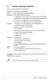
... following items. Model Name TS700-E8-PS4, TS700-E8-RS8 Chassis ASUS T50A Pedestal / 5U Rackmount Chassis Motherboard ASUS Z10PE-D16 WS Server Board 1 x 1200W 80PLUS Platinum Single Power Supply Module (TS700-E8-PS4) 1 x 800W 80PLUS Gold Redundant Power Supply Module (TS700-E8-RS8) 4 x Hot-swap 3.5-inch HDD Trays (Front panel, TS700-E8-PS4) 8 x Hot-swap 3.5-inch HDD Trays (Front panel, TS700-E8-RS8)* Component 2 x Hot-swap...
... following items. Model Name TS700-E8-PS4, TS700-E8-RS8 Chassis ASUS T50A Pedestal / 5U Rackmount Chassis Motherboard ASUS Z10PE-D16 WS Server Board 1 x 1200W 80PLUS Platinum Single Power Supply Module (TS700-E8-PS4) 1 x 800W 80PLUS Gold Redundant Power Supply Module (TS700-E8-RS8) 4 x Hot-swap 3.5-inch HDD Trays (Front panel, TS700-E8-PS4) 8 x Hot-swap 3.5-inch HDD Trays (Front panel, TS700-E8-RS8)* Component 2 x Hot-swap...

User Guide
Page 15
With the correct serial number of the product's serial number containing 14 characters such as xxS0xxxxxxxxxx shown as the figure below. 1.2 Serial number label Before requesting support from the ASUS Technical Support team, you must take note of the product, ASUS Technical Support team members can then offer a quicker and satisfying solution to your problems. TS700-E8-PS4 xxS0xxxxxxxxxx TS700-E8-RS8 xxS0xxxxxxxxxx ASUS TS700-E8-PS4, TS700-E8-RS8 1-3
With the correct serial number of the product's serial number containing 14 characters such as xxS0xxxxxxxxxx shown as the figure below. 1.2 Serial number label Before requesting support from the ASUS Technical Support team, you must take note of the product, ASUS Technical Support team members can then offer a quicker and satisfying solution to your problems. TS700-E8-PS4 xxS0xxxxxxxxxx TS700-E8-RS8 xxS0xxxxxxxxxx ASUS TS700-E8-PS4, TS700-E8-RS8 1-3

User Guide
Page 16
...NVDIMM Memory Type Refer to www.asus.com for the latest memory AVL update. 32GB, 16GB, 8GB and 4GB (RDIMM) Memory Size 64GB, 32GB (LRDIMM) Refer to www.asus.com for the latest memory AVL update. 1.3 System specifications The ASUS TS700-E8-PS4, TS700-E8-RS8 is a Pedestal / 5U Rackmount... barebone server system featuring the ASUS Z10PE-D16 WS Server Board. The server supports Intel® LGA2011-3 ...
...NVDIMM Memory Type Refer to www.asus.com for the latest memory AVL update. 32GB, 16GB, 8GB and 4GB (RDIMM) Memory Size 64GB, 32GB (LRDIMM) Refer to www.asus.com for the latest memory AVL update. 1.3 System specifications The ASUS TS700-E8-PS4, TS700-E8-RS8 is a Pedestal / 5U Rackmount... barebone server system featuring the ASUS Z10PE-D16 WS Server Board. The server supports Intel® LGA2011-3 ...

User Guide
Page 17
ASUS TS700-E8-PS4, TS700-E8-RS8 1-5 Refer to www.asus.com for KVM-over-Internet Dimensions (HH x WW x DD) Net Weight Kg (CPU, DRAM & HDD not included) Power Supply Power Rating Environment 455 mm x 217.... 3 x 5.25" media bays (Options: No Device / DVD-RW) 1 x PS/2 keyboard/mouse combo port 1 x Q-Code Logger button with LED 1 x BIOS Flashback button with LED TS700-E8-RS8 1 x S/PDIF Out port Onboard I/O Connectors / LED 1 x RJ-45 management port indicators 2 x RJ-45 GbE port OS Support 8-channel Audio I Operating temperature: 10°C - 35°C ...
ASUS TS700-E8-PS4, TS700-E8-RS8 1-5 Refer to www.asus.com for KVM-over-Internet Dimensions (HH x WW x DD) Net Weight Kg (CPU, DRAM & HDD not included) Power Supply Power Rating Environment 455 mm x 217.... 3 x 5.25" media bays (Options: No Device / DVD-RW) 1 x PS/2 keyboard/mouse combo port 1 x Q-Code Logger button with LED 1 x BIOS Flashback button with LED TS700-E8-RS8 1 x S/PDIF Out port Onboard I/O Connectors / LED 1 x RJ-45 management port indicators 2 x RJ-45 GbE port OS Support 8-channel Audio I Operating temperature: 10°C - 35°C ...

User Guide
Page 19
1.5 Rear panel features TS700-E8-PS4 Power connector PS/2 keyboard/ mouse combo port 2 x USB 2.0 ports BIOS Flashback button with LED 2 x USB 2.0 ports 4 x USB 3.0 ports Audio I/O ports USB BIOS Flashback SPDIF OUT Management USB3.0 USB3.0 side rear c/sub MIC IN LINE OUT LINE IN KY Q-Code Logger VGA port 120mm x 38mm system fan Q-Code Logger button with LED SPDIF Out port Management LAN port* LAN (RJ-45) port 2 LAN (RJ-45) port 1 Expansion slots * This port is for ASUS ASMB8-iKVM controller and for techincians only. LAN port 3 LAN port 1 ASUS TS700-E8-PS4, TS700-E8-RS8 1-7
1.5 Rear panel features TS700-E8-PS4 Power connector PS/2 keyboard/ mouse combo port 2 x USB 2.0 ports BIOS Flashback button with LED 2 x USB 2.0 ports 4 x USB 3.0 ports Audio I/O ports USB BIOS Flashback SPDIF OUT Management USB3.0 USB3.0 side rear c/sub MIC IN LINE OUT LINE IN KY Q-Code Logger VGA port 120mm x 38mm system fan Q-Code Logger button with LED SPDIF Out port Management LAN port* LAN (RJ-45) port 2 LAN (RJ-45) port 1 Expansion slots * This port is for ASUS ASMB8-iKVM controller and for techincians only. LAN port 3 LAN port 1 ASUS TS700-E8-PS4, TS700-E8-RS8 1-7

User Guide
Page 20
LAN port 3 LAN port 1 1-8 Chapter 1: Product introduction TS700-E8-RS8 Power connectors PS/2 keyboard/ mouse combo port 2 x USB 2.0 ports BIOS Flashback button with LED 2 x USB 2.0 ports 4 x USB 3.0 ports Audio I/O ports USB BIOS Flashback SPDIF OUT Management USB3.0 USB3.0 side rear c/sub MIC IN LINE OUT LINE IN KY Q-Code Logger 2 x 2.5-inch SSD bays 120mm x 38mm system fan Q-Code Logger button with LED SPDIF Out port Management LAN port* LAN (RJ-45) port 2 LAN (RJ-45) port 1 VGA port Expansion slots * This port is for ASUS ASMB8-iKVM controller and for techincians only.
LAN port 3 LAN port 1 1-8 Chapter 1: Product introduction TS700-E8-RS8 Power connectors PS/2 keyboard/ mouse combo port 2 x USB 2.0 ports BIOS Flashback button with LED 2 x USB 2.0 ports 4 x USB 3.0 ports Audio I/O ports USB BIOS Flashback SPDIF OUT Management USB3.0 USB3.0 side rear c/sub MIC IN LINE OUT LINE IN KY Q-Code Logger 2 x 2.5-inch SSD bays 120mm x 38mm system fan Q-Code Logger button with LED SPDIF Out port Management LAN port* LAN (RJ-45) port 2 LAN (RJ-45) port 1 VGA port Expansion slots * This port is for ASUS ASMB8-iKVM controller and for techincians only.

User Guide
Page 21
... panel if you need to any system component. The barebone server does not include a floppy disk drive drive. ASUS Z10PE-D16 WS Server Board 4. Expansion card locks 6. Connect a USB floppy disk drive to use a floppy disk. *WARNING HAZARDOUS MOVING PARTS KEEP FINGERS AND OTHER BODY PARTS AWAY ASUS TS700-E8-PS4, TS700-E8-RS8 1-9 Chassis intrusion switch 5.
... panel if you need to any system component. The barebone server does not include a floppy disk drive drive. ASUS Z10PE-D16 WS Server Board 4. Expansion card locks 6. Connect a USB floppy disk drive to use a floppy disk. *WARNING HAZARDOUS MOVING PARTS KEEP FINGERS AND OTHER BODY PARTS AWAY ASUS TS700-E8-PS4, TS700-E8-RS8 1-9 Chassis intrusion switch 5.

User Guide
Page 23
Q-Code Logger USB BIOS Flashback 1.7.2 SPDIF OUT LAN (RJ-45) LEDs Management USB3.0 USB3.0 ACT/LINKsideLEDrear c/sub Status Description OFF No link MIC IN LINE OUT LINE IN ORANGE BLINKING Linked KY Data activity ACT/LINK LED SPEED LED ACT/LINK LED SPEED LED SPEED LED Status Description OFF 10 Mbps connection ORANGE 100 Mbps connection GREEN 1 Gbps connection ASUS TS700-E8-PS4, TS700-E8-RS8 1-11
Q-Code Logger USB BIOS Flashback 1.7.2 SPDIF OUT LAN (RJ-45) LEDs Management USB3.0 USB3.0 ACT/LINKsideLEDrear c/sub Status Description OFF No link MIC IN LINE OUT LINE IN ORANGE BLINKING Linked KY Data activity ACT/LINK LED SPEED LED ACT/LINK LED SPEED LED SPEED LED Status Description OFF 10 Mbps connection ORANGE 100 Mbps connection GREEN 1 Gbps connection ASUS TS700-E8-PS4, TS700-E8-RS8 1-11

User Guide
Page 27
Drive in place. 3. 2.1.2 Reinstalling the side cover To reinstall the side cover: 1. Slide the side cover toward the front panel until it snaps in the two screws you removed earlier to the corresponding chassis edge. 2. Match and insert the lower sliding edge of the side cover to secure the side cover. 1 3 1 2 3 ASUS TS700-E8-PS4, TS700-E8-RS8 2-3
Drive in place. 3. 2.1.2 Reinstalling the side cover To reinstall the side cover: 1. Slide the side cover toward the front panel until it snaps in the two screws you removed earlier to the corresponding chassis edge. 2. Match and insert the lower sliding edge of the side cover to secure the side cover. 1 3 1 2 3 ASUS TS700-E8-PS4, TS700-E8-RS8 2-3
User Guide
Page 29
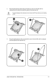
Press the left (E) until it is released from then gently lift the load lever (F). ASUS TS700-E8-PS4, TS700-E8-RS8 2-5 2. To prevent damage to the right until it is released from the retention tab (B) then gently lift the load lever (C). Load lever 3. Press the right load lever with your thumb (D), move it to the left load lever down with your thumb (A), move it to the socket pins, do not remove the PnP cap unless you are installing a CPU.
Press the left (E) until it is released from then gently lift the load lever (F). ASUS TS700-E8-PS4, TS700-E8-RS8 2-5 2. To prevent damage to the right until it is released from the retention tab (B) then gently lift the load lever (C). Load lever 3. Press the right load lever with your thumb (D), move it to the left load lever down with your thumb (A), move it to the socket pins, do not remove the PnP cap unless you are installing a CPU.

User Guide
Page 31
... only if the motherboard comes with the PnP cap on the LGA 2011 socket. Keep the PnP cap. PnP cap 11. 10. Retention tab ASUS TS700-E8-PS4, TS700-E8-RS8 2-7 Push down the right load lever (I) ensuring that the edge of the load plate when the right load lever is fixed and tucked securely under...
... only if the motherboard comes with the PnP cap on the LGA 2011 socket. Keep the PnP cap. PnP cap 11. 10. Retention tab ASUS TS700-E8-PS4, TS700-E8-RS8 2-7 Push down the right load lever (I) ensuring that the edge of the load plate when the right load lever is fixed and tucked securely under...
User Guide
Page 33
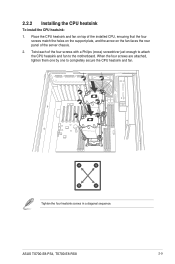
... screws in a diagonal sequence. When the four screws are attached, tighten them one by one to the motherboard. Twist each of the server chassis. 2. ASUS TS700-E8-PS4, TS700-E8-RS8 2-9 Place the CPU heatsink and fan on top of the installed CPU, ensuring that the four screws match the holes on the support plate, and...
... screws in a diagonal sequence. When the four screws are attached, tighten them one by one to the motherboard. Twist each of the server chassis. 2. ASUS TS700-E8-PS4, TS700-E8-RS8 2-9 Place the CPU heatsink and fan on top of the installed CPU, ensuring that the four screws match the holes on the support plate, and...

User Guide
Page 35
... (CPU2) A2 A1 B2 B1 C2 C1 D2 D1 E2 E1 F2 F1 G2 G1 H2 H1 2 DIMMs P P 4 DIMMs P P P P 8 DIMMs P P P P P P P P 12 DIMMs P P P P P PPPPP P P 16 DIMMs P P P P P P P P P P P P P P P P ASUS TS700-E8-PS4, TS700-E8-RS8 2-11 Single CPU configuration You can refer to the following recommended memory population for a single CPU configuration.
... (CPU2) A2 A1 B2 B1 C2 C1 D2 D1 E2 E1 F2 F1 G2 G1 H2 H1 2 DIMMs P P 4 DIMMs P P P P 8 DIMMs P P P P P P P P 12 DIMMs P P P P P PPPPP P P 16 DIMMs P P P P P P P P P P P P P P P P ASUS TS700-E8-PS4, TS700-E8-RS8 2-11 Single CPU configuration You can refer to the following recommended memory population for a single CPU configuration.

User Guide
Page 37
... panel assembly: 1. Hook the other side of the front panel assembly to the chassis. 2. Locate the three hooked tabs on the chassis side rail. 2. ASUS TS700-E8-PS4, TS700-E8-RS8 2-13 2.4 Front panel assembly Before you can install a 5.25-inch drive, you should first remove the front panel assembly (front bezel and front panel cover...
... panel assembly: 1. Hook the other side of the front panel assembly to the chassis. 2. Locate the three hooked tabs on the chassis side rail. 2. ASUS TS700-E8-PS4, TS700-E8-RS8 2-13 2.4 Front panel assembly Before you can install a 5.25-inch drive, you should first remove the front panel assembly (front bezel and front panel cover...

User Guide
Page 39
Find a HDD tray. Locate an empty bay and insert the HDD tray into the bay. 4. ASUS TS700-E8-PS4, TS700-E8-RS8 2-15 Insert the HDD module cage into the bay. 2. Level the HDD module cage latch counterclockwise. 3. 2.5.2 Installing the HDD module cage 1. Lock the cage latch properly. 6. When the HDD module cage is completely inserted, the cage latch will be pushed back clockwise. 5. Connect the appropriate cables to the SATA/SAS backplane on the HDD module cage. 3 2 4 5 By default, only TS700-E8-RS8 supports the second set of HDD module.
Find a HDD tray. Locate an empty bay and insert the HDD tray into the bay. 4. ASUS TS700-E8-PS4, TS700-E8-RS8 2-15 Insert the HDD module cage into the bay. 2. Level the HDD module cage latch counterclockwise. 3. 2.5.2 Installing the HDD module cage 1. Lock the cage latch properly. 6. When the HDD module cage is completely inserted, the cage latch will be pushed back clockwise. 5. Connect the appropriate cables to the SATA/SAS backplane on the HDD module cage. 3 2 4 5 By default, only TS700-E8-RS8 supports the second set of HDD module.

User Guide
Page 41
.../SAS interface on each side to the depth of the bay until just a small fraction of hard disk drives. 2. Use two screws on the backplane. ASUS TS700-E8-PS4, TS700-E8-RS8 2-17 Take note of the bay. 3. Firmly hold the tray lever and pull the drive tray out of the drive tray holes. Place a SATA...
.../SAS interface on each side to the depth of the bay until just a small fraction of hard disk drives. 2. Use two screws on the backplane. ASUS TS700-E8-PS4, TS700-E8-RS8 2-17 Take note of the bay. 3. Firmly hold the tray lever and pull the drive tray out of the drive tray holes. Place a SATA...

User Guide
Page 43
6. Carefully insert the drive tray with the chassis cover. 9. Repeat steps 1 to 8 to the drive bay. ASUS TS700-E8-PS4, TS700-E8-RS8 2-19 Ensure that the SSD is fitted firmly inside the drive tray and that the four screws of the SSD matches the four screws holes ...
6. Carefully insert the drive tray with the chassis cover. 9. Repeat steps 1 to 8 to the drive bay. ASUS TS700-E8-PS4, TS700-E8-RS8 2-19 Ensure that the SSD is fitted firmly inside the drive tray and that the four screws of the SSD matches the four screws holes ...

User Guide
Page 45
... surface. 3. Failure to do so may cause severe damage to unplug the power cord before installing an expansion card. Remove the side chassis cover. ASUS TS700-E8-PS4, TS700-E8-RS8 2-21 Before installing the expansion card, read the documentation that came with it and make the necessary hardware settings for the card. Lay the system...
... surface. 3. Failure to do so may cause severe damage to unplug the power cord before installing an expansion card. Remove the side chassis cover. ASUS TS700-E8-PS4, TS700-E8-RS8 2-21 Before installing the expansion card, read the documentation that came with it and make the necessary hardware settings for the card. Lay the system...

User Guide
Page 47
Assign an IRQ to the following tables. 3. ASUS TS700-E8-PS4, TS700-E8-RS8 2-23 2.7.2 Configuring an expansion card After installing the expansion card, configure it by adjusting the software settings. 1. Programmable Interrupt 3* 11 Communications Port (COM2) 4* 12 Communications ...
Assign an IRQ to the following tables. 3. ASUS TS700-E8-PS4, TS700-E8-RS8 2-23 2.7.2 Configuring an expansion card After installing the expansion card, configure it by adjusting the software settings. 1. Programmable Interrupt 3* 11 Communications Port (COM2) 4* 12 Communications ...


