User Guide
Page 11
Product introduction Chapter 1 This chapter describes the general features of the server, including sections on front panel and rear panel specifications. ASUS TS500-E6/PS4
Product introduction Chapter 1 This chapter describes the general features of the server, including sections on front panel and rear panel specifications. ASUS TS500-E6/PS4
User Guide
Page 12
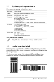
... x 120mm x 38mm) Accessories 1 x TS500-E6 User's Guide 1 x ASUS ASWM 2.0 User's Guide 1 x TS500-E6 Support CD (including ASWM*) 1 x Bag of Screws 1 x AC Power Cable 1 x Anti-virus CD (Optional) Optional Items CPU Cooler DVD-ROM / DVD-RW ASUS TS500-E6 Rackmount Rail Kit *ASUS System Web-based Management If any of the ...above items is damaged or missing, contact your retailer. 1.2 Serial number label Before requesting support from the ASUS Technical Support team, you must take note...
... x 120mm x 38mm) Accessories 1 x TS500-E6 User's Guide 1 x ASUS ASWM 2.0 User's Guide 1 x TS500-E6 Support CD (including ASWM*) 1 x Bag of Screws 1 x AC Power Cable 1 x Anti-virus CD (Optional) Optional Items CPU Cooler DVD-ROM / DVD-RW ASUS TS500-E6 Rackmount Rail Kit *ASUS System Web-based Management If any of the ...above items is damaged or missing, contact your retailer. 1.2 Serial number label Before requesting support from the ASUS Technical Support team, you must take note...
User Guide
Page 13
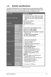
... 3.5" HDD Bays swappable (continued on the next page) ASUS TS500-E6/PS4 1-3 Supports software RAID 0, 1, 5 & 10 LSI MegaRAID (for Windows only) - 1.3 System specifications The ASUS TS500-E6/PS4 is a 5U barebone server system featuring the ASUS Z8NA-D6 server board. Supports RAID 0,1,5,10 & 6 ASUS PIKE 6480 SAS RAID card - Model Name TS500-E6/PS4 2 x Socket LGA1366 Processor / System Bus - Supports...
... 3.5" HDD Bays swappable (continued on the next page) ASUS TS500-E6/PS4 1-3 Supports software RAID 0, 1, 5 & 10 LSI MegaRAID (for Windows only) - 1.3 System specifications The ASUS TS500-E6/PS4 is a 5U barebone server system featuring the ASUS Z8NA-D6 server board. Supports RAID 0,1,5,10 & 6 ASUS PIKE 6480 SAS RAID card - Model Name TS500-E6/PS4 2 x Socket LGA1366 Processor / System Bus - Supports...
User Guide
Page 15
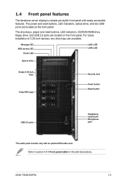
For future installation of 5.25-inch devices, two drive bays are located on the front panel. ASUS TS500-E6/PS4 1-5 The drive bays, power and reset buttons, LED indicators, CD/DVD-ROM drive, floppy drive, and USB 2.0 ports are located on the front panel. ...
For future installation of 5.25-inch devices, two drive bays are located on the front panel. ASUS TS500-E6/PS4 1-5 The drive bays, power and reset buttons, LED indicators, CD/DVD-ROM drive, floppy drive, and USB 2.0 ports are located on the front panel. ...
User Guide
Page 17
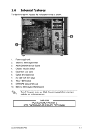
Chassis intrusion switch 5. ASUS Z8NA-D6 Server Board 4. Optical drive (optional) 7. 2 x 5.25-inch drive bays 8. 4-bay HDD module 9. SATA/SAS backplane board 10. 80mm x 38mm system fan (hidden) Turn off the system power and detach the power supply before removing or replacing any system component. *WARNING HAZARDOUS MOVING PARTS KEEP FINGERS AND OTHER BODY PARTS AWAY ASUS TS500-E6/PS4 1-7 1.6 Internal features The barebone server includes the basic components as shown. 1 6 7 2 9 8 3 4 10 5 1. Power supply unit: 2. 120mm x 38mm system fan 3. Expansion card locks 6.
Chassis intrusion switch 5. ASUS Z8NA-D6 Server Board 4. Optical drive (optional) 7. 2 x 5.25-inch drive bays 8. 4-bay HDD module 9. SATA/SAS backplane board 10. 80mm x 38mm system fan (hidden) Turn off the system power and detach the power supply before removing or replacing any system component. *WARNING HAZARDOUS MOVING PARTS KEEP FINGERS AND OTHER BODY PARTS AWAY ASUS TS500-E6/PS4 1-7 1.6 Internal features The barebone server includes the basic components as shown. 1 6 7 2 9 8 3 4 10 5 1. Power supply unit: 2. 120mm x 38mm system fan 3. Expansion card locks 6.
User Guide
Page 19
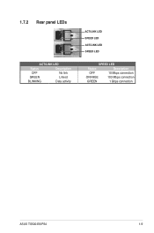
1.7.2 Rear panel LEDs ACT/LINK LED Status Description OFF No link GREEN Linked BLINKING Data activity ACT/LINK LED SPEED LED ACT/LINK LED SPEED LED SPEED LED Status Description OFF 10 Mbps connection ORANGE 100 Mbps connection GREEN 1 Gbps connection ASUS TS500-E6/PS4 1-9
1.7.2 Rear panel LEDs ACT/LINK LED Status Description OFF No link GREEN Linked BLINKING Data activity ACT/LINK LED SPEED LED ACT/LINK LED SPEED LED SPEED LED Status Description OFF 10 Mbps connection ORANGE 100 Mbps connection GREEN 1 Gbps connection ASUS TS500-E6/PS4 1-9
User Guide
Page 21
ASUS TS500-E6/PS4 Hardware setup Chapter 2 This chapter lists the hardware setup procedures that you have to perform when installing or removing system components.
ASUS TS500-E6/PS4 Hardware setup Chapter 2 This chapter lists the hardware setup procedures that you have to perform when installing or removing system components.
User Guide
Page 23
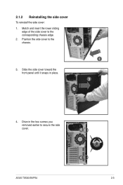
Drive in place. 1 3 4. 2.1.2 Reinstalling the side cover To reinstall the side cover: 1. Match and insert the lower sliding edge of the side cover to the chassis. 3. Slide the side cover toward the front panel until it snaps in the two screws you removed earlier to secure the side cover. 4 ASUS TS500-E6/PS4 4 2-3 Position the side cover to the corresponding chassis edge. 2.
Drive in place. 1 3 4. 2.1.2 Reinstalling the side cover To reinstall the side cover: 1. Match and insert the lower sliding edge of the side cover to the chassis. 3. Slide the side cover toward the front panel until it snaps in the two screws you removed earlier to secure the side cover. 4 ASUS TS500-E6/PS4 4 2-3 Position the side cover to the corresponding chassis edge. 2.
User Guide
Page 25
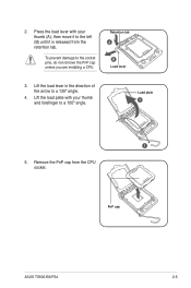
Load plate 4 3 5. PnP cap ASUS TS500-E6/PS4 2-5 Press the load lever with your thumb (A), then move it to a 100º angle. Retention tab A B Load lever 3. Lift the load lever in the direction of the arrow to the socket pins, do not remove the PnP cap unless you are installing a CPU. 2. Remove the PnP cap from the retention tab. To prevent damage to a 135º angle. 4. Lift the load plate with your thumb and forefinger to the left (B) until it is released from the CPU socket.
Load plate 4 3 5. PnP cap ASUS TS500-E6/PS4 2-5 Press the load lever with your thumb (A), then move it to a 100º angle. Retention tab A B Load lever 3. Lift the load lever in the direction of the arrow to the socket pins, do not remove the PnP cap unless you are installing a CPU. 2. Remove the PnP cap from the retention tab. To prevent damage to a 135º angle. 4. Lift the load plate with your thumb and forefinger to the left (B) until it is released from the CPU socket.
User Guide
Page 27
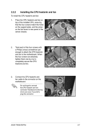
... the holes on the support plate, and the arrow on the motherboard. 2.2.2 Installing the CPU heatsink and fan To install the CPU heatsink and fan: 1. ASUS TS500-E6/PS4 2-7 Place the CPU heatsink and fan on top of the four screws with a Philips (cross) screwdriver just enough to attach the CPU heatsink and...
... the holes on the support plate, and the arrow on the motherboard. 2.2.2 Installing the CPU heatsink and fan To install the CPU heatsink and fan: 1. ASUS TS500-E6/PS4 2-7 Place the CPU heatsink and fan on top of the four screws with a Philips (cross) screwdriver just enough to attach the CPU heatsink and...
User Guide
Page 29
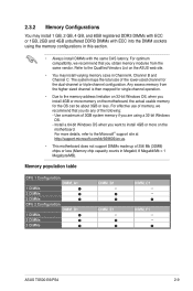
...does not support DIMMs made up of 3GB system memory if you are using the memory configurations in Megabit, 8 Megabit/Mb = 1 Megabyte/MB). DIMM_E1 -- ASUS TS500-E6/PS4 2-9 Use a maximum of 256 Mb (32MB) chips or less (Memory chip capacity counts in this section. • Always install DIMMs with ECC into ...DIMMs 2 DIMMs 3 DIMMs DIMM_B1 -- Any excess memory from the same vendor. For optimum compatibility, we recommend that you install 4GB or more on the ASUS web site. • You may install 1 GB, 2 GB, 4 GB, and 8GB registered DDR3 DIMMs with ECC or 1GB, 2GB and 4GB ...
...does not support DIMMs made up of 3GB system memory if you are using the memory configurations in Megabit, 8 Megabit/Mb = 1 Megabyte/MB). DIMM_E1 -- ASUS TS500-E6/PS4 2-9 Use a maximum of 256 Mb (32MB) chips or less (Memory chip capacity counts in this section. • Always install DIMMs with ECC into ...DIMMs 2 DIMMs 3 DIMMs DIMM_B1 -- Any excess memory from the same vendor. For optimum compatibility, we recommend that you install 4GB or more on the ASUS web site. • You may install 1 GB, 2 GB, 4 GB, and 8GB registered DDR3 DIMMs with ECC or 1GB, 2GB and 4GB ...
User Guide
Page 31
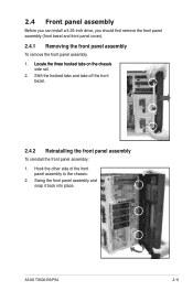
Hook the other side of the front panel assembly to the chassis. 2. ASUS TS500-E6/PS4 2-11 Shift the hooked tabs and take off the front bezel. 2.4.2 Reinstalling the front panel assembly To reinstall the front panel assembly: 1. Swing the ...
Hook the other side of the front panel assembly to the chassis. 2. ASUS TS500-E6/PS4 2-11 Shift the hooked tabs and take off the front bezel. 2.4.2 Reinstalling the front panel assembly To reinstall the front panel assembly: 1. Swing the ...
User Guide
Page 33
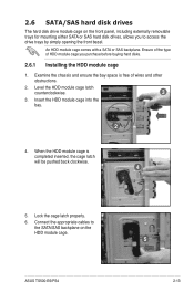
... the chassis and ensure the bay space is completed inserted, the cage latch will be pushed back clockwise. 4 5. Level the HDD module cage latch counterclockwise. 3 3. ASUS TS500-E6/PS4 5 2-13 Ensure of the type of wires and other obstructions. 2. Insert the HDD module cage into the bay. 2 4. An HDD module cage comes with...
... the chassis and ensure the bay space is completed inserted, the cage latch will be pushed back clockwise. 4 5. Level the HDD module cage latch counterclockwise. 3 3. ASUS TS500-E6/PS4 5 2-13 Ensure of the type of wires and other obstructions. 2. Insert the HDD module cage into the bay. 2 4. An HDD module cage comes with...
User Guide
Page 35
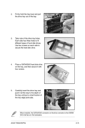
.... 4. Place a SATAII/SAS hard disk drive on the backplane. Firmly hold the tray lever and pull the drive tray out of the drive tray holes. ASUS TS500-E6/PS4 2-15 Take note of the bay. 3. 2.
.... 4. Place a SATAII/SAS hard disk drive on the backplane. Firmly hold the tray lever and pull the drive tray out of the drive tray holes. ASUS TS500-E6/PS4 2-15 Take note of the bay. 3. 2.
User Guide
Page 37
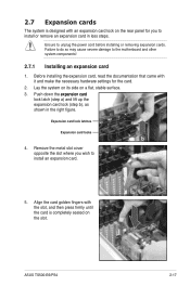
... came with the slot, and then press firmly until the card is designed with an expansion card lock on the rear panel for the card. 2. ASUS TS500-E6/PS4 2-17 Expansion card lock latches Expansion card locks b 4. Ensure to the motherboard and other system components! 2.7.1 Installing an expansion card 1. Push down the �...
... came with the slot, and then press firmly until the card is designed with an expansion card lock on the rear panel for the card. 2. ASUS TS500-E6/PS4 2-17 Expansion card lock latches Expansion card locks b 4. Ensure to the motherboard and other system components! 2.7.1 Installing an expansion card 1. Push down the �...
User Guide
Page 39
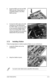
... and blue). 2.7.3 Installing i Button Follow the steps below to install I Button before using PIKE 1078 functions. Ensure that it is completely seated on your motherboard. 1. ASUS TS500-E6/PS4 2-19 You need to install an optional i Button on the PIKE RAID card slot. 4.
... and blue). 2.7.3 Installing i Button Follow the steps below to install I Button before using PIKE 1078 functions. Ensure that it is completely seated on your motherboard. 1. ASUS TS500-E6/PS4 2-19 You need to install an optional i Button on the PIKE RAID card slot. 4.
User Guide
Page 41
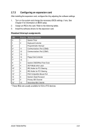
... drivers for ISA or PCI devices. Refer to the card. See Chapter 5 for information on the system and change the necessary BIOS settings, if any. ASUS TS500-E6/PS4 2-21
... drivers for ISA or PCI devices. Refer to the card. See Chapter 5 for information on the system and change the necessary BIOS settings, if any. ASUS TS500-E6/PS4 2-21
User Guide
Page 43
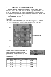
2.8.2 SATA/SAS backplane connections A SATA/SAS backplane comes pre-installed in the TS500-E6. Refer to indicate HDD status. The LEDs on the backplane connect to the front panel LEDs to the table for reference. HDD1 HDD2 HDD3 Drive ... installed. HDD Device HDD 1 HDD 2 HDD 3 HDD 4 Front side connector HDD1 HDD2 HDD3 HDD4 Back side connector CON�1 CON�2 CON�3 CON�4 ASUS TS500-E6/PS4 2-23 Front side The front side of the backplane. See section 1.7 LED information for the hot swap drive trays. The SATA/SAS backplane has...
2.8.2 SATA/SAS backplane connections A SATA/SAS backplane comes pre-installed in the TS500-E6. Refer to indicate HDD status. The LEDs on the backplane connect to the front panel LEDs to the table for reference. HDD1 HDD2 HDD3 Drive ... installed. HDD Device HDD 1 HDD 2 HDD 3 HDD 4 Front side connector HDD1 HDD2 HDD3 HDD4 Back side connector CON�1 CON�2 CON�3 CON�4 ASUS TS500-E6/PS4 2-23 Front side The front side of the backplane. See section 1.7 LED information for the hot swap drive trays. The SATA/SAS backplane has...
User Guide
Page 45
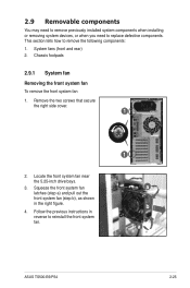
... You may need to remove previously installed system components when installing or removing system devices, or when you need to reinstall the front system fan. 1 a b a ASUS TS500-E6/PS4 2-25 Squeeze the front system fan latches (step a) and pull out the front system fan (step b), as shown in reverse to replace defective components...
... You may need to remove previously installed system components when installing or removing system devices, or when you need to reinstall the front system fan. 1 a b a ASUS TS500-E6/PS4 2-25 Squeeze the front system fan latches (step a) and pull out the front system fan (step b), as shown in reverse to replace defective components...
User Guide
Page 47
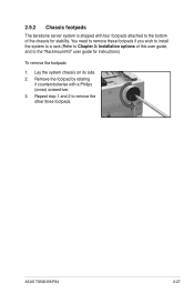
Lay the system chassis on its side. 2. You need to remove these footpads if you wish to install the system to a rack (Refer to Chapter 3: Installation options of the chassis for instructions) To remove the footpads 1. Repeat step 1 and 2 to the "Rackmount Kit" user guide for stability. ASUS TS500-E6/PS4 2-27 Remove the footpad by rotating it counterclockwise with four footpads attached to the bottom of this user guide, and to remove the other three footpads. 2.9.2 Chassis footpads The barebone server system is shipped with a Philips (cross) screwdriver. 3.
Lay the system chassis on its side. 2. You need to remove these footpads if you wish to install the system to a rack (Refer to Chapter 3: Installation options of the chassis for instructions) To remove the footpads 1. Repeat step 1 and 2 to the "Rackmount Kit" user guide for stability. ASUS TS500-E6/PS4 2-27 Remove the footpad by rotating it counterclockwise with four footpads attached to the bottom of this user guide, and to remove the other three footpads. 2.9.2 Chassis footpads The barebone server system is shipped with a Philips (cross) screwdriver. 3.