T2-PH2 User''s Manual for English Edition
Page 3
...panel (internal 1-5 1.4 Rear panel 1-7 1.5 Internal components 1-9 1.6 LED panel 1-10 Chapter 2: Basic Installation 2.1 Preparation 2-2 2.2 Before you proceed 2-2 2.3 Removing the cover 2-3 2.4 Removing the power supply 2-4 2.5 Installing a CPU 2-5 2.5.1 Removing the CPU fan and heatsink assembly ....... 2-5 2.5.2 CPU installation 2-6 2.5.3 Reinstalling the CPU fan and heatsink assembly ..... 2-9 2.6 Installing a DIMM 2-10 ... a floppy disk drive 2-20 2.10 Installing a hard disk drive (HDD 2-21 2.11 Reinstalling the power supply unit 2-24 2.12 Replacing the cover 2-26 iii
...panel (internal 1-5 1.4 Rear panel 1-7 1.5 Internal components 1-9 1.6 LED panel 1-10 Chapter 2: Basic Installation 2.1 Preparation 2-2 2.2 Before you proceed 2-2 2.3 Removing the cover 2-3 2.4 Removing the power supply 2-4 2.5 Installing a CPU 2-5 2.5.1 Removing the CPU fan and heatsink assembly ....... 2-5 2.5.2 CPU installation 2-6 2.5.3 Reinstalling the CPU fan and heatsink assembly ..... 2-9 2.6 Installing a DIMM 2-10 ... a floppy disk drive 2-20 2.10 Installing a hard disk drive (HDD 2-21 2.11 Reinstalling the power supply unit 2-24 2.12 Replacing the cover 2-26 iii
T2-PH2 User''s Manual for English Edition
Page 5
... 5.4.2 LAN Cable Status 5-20 5.4.3 USB Configuration 5-21 5.4.4 CPU Configuration 5-22 5.4.5 Chipset 5-24 5.4.6 Onboard Devices Configuration 5-26 5.4.7 PCI PnP 5-28 5.5 Power menu 5-30 5.5.1 Suspend Mode 5-30 5.5.2 ACPI 2.0 Support 5-30 5.5.3 ACPI APIC Support 5-30 5.5.4 APM Configuration 5-31 5.5.5 Hardware Monitor 5-33 5.6 Boot menu 5-34 5.6.1 Boot Device...
... 5.4.2 LAN Cable Status 5-20 5.4.3 USB Configuration 5-21 5.4.4 CPU Configuration 5-22 5.4.5 Chipset 5-24 5.4.6 Onboard Devices Configuration 5-26 5.4.7 PCI PnP 5-28 5.5 Power menu 5-30 5.5.1 Suspend Mode 5-30 5.5.2 ACPI 2.0 Support 5-30 5.5.3 ACPI APIC Support 5-30 5.5.4 APM Configuration 5-31 5.5.5 Hardware Monitor 5-33 5.6 Boot menu 5-34 5.6.1 Boot Device...

T2-PH2 User''s Manual for English Edition
Page 7
... technician or your retailer. Operation safety • Before installing devices into the system, carefully read all cables are correctly connected and the power cables are connected. • If the power supply is incorrectly replaced. Ersatz nur durch denselben oder einem vom Hersteller empfohlenem ähnljchen Typ. Entsorgung gebrauchter Batterien nach Angaben des Herstellers...
... technician or your retailer. Operation safety • Before installing devices into the system, carefully read all cables are correctly connected and the power cables are connected. • If the power supply is incorrectly replaced. Ersatz nur durch denselben oder einem vom Hersteller empfohlenem ähnljchen Typ. Entsorgung gebrauchter Batterien nach Angaben des Herstellers...
T2-PH2 User''s Manual for English Edition
Page 8
... system settings through the BIOS Setup menus and describes the BIOS parameters. 6. Chapter 4: Motherboard information This chapter gives information about the ASUS T2-PH2 barebone system. viii Appendix The Appendix includes the power supply unit specification for experienced users and integrators with the system. Chapter 5: BIOS information This chapter tells how to install...
... system settings through the BIOS Setup menus and describes the BIOS parameters. 6. Chapter 4: Motherboard information This chapter gives information about the ASUS T2-PH2 barebone system. viii Appendix The Appendix includes the power supply unit specification for experienced users and integrators with the system. Chapter 5: BIOS information This chapter tells how to install...
T2-PH2 User''s Manual for English Edition
Page 10
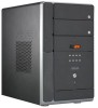
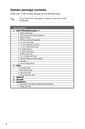
... package for the following items. If any of the items is damaged or missing, contact your retailer immediately. Item description 1. ASUS T2-PH2 barebone system with • ASUS motherboard • 250 W Passive PFC power supply unit • Gigabit LAN port • CPU fan and heatsink assembly • 2 x 5.25" drive bays • 1 x 3.5" floppy disk ...ports • 7-in-1 storage card reader • FM radio module and radio antenna • LED panel • Audio DJ play buttons 2. Cables • AC power cable • Ultra ATA 66 cable • Serial ATA cable • Serial ATA...
... package for the following items. If any of the items is damaged or missing, contact your retailer immediately. Item description 1. ASUS T2-PH2 barebone system with • ASUS motherboard • 250 W Passive PFC power supply unit • Gigabit LAN port • CPU fan and heatsink assembly • 2 x 5.25" drive bays • 1 x 3.5" floppy disk ...ports • 7-in-1 storage card reader • FM radio module and radio antenna • LED panel • Audio DJ play buttons 2. Cables • AC power cable • Ultra ATA 66 cable • Serial ATA cable • Serial ATA...
T2-PH2 User''s Manual for English Edition
Page 18
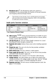
... 2.0) ports are available for details. 1-8 Chapter 1: System introduction This port allows Gigabit connection to the table below for the power cable and plug. 17. Power supply unit fan vent. This vent is for the fan that provides ventilation inside the system chassis. 14. This switch allows you select... vent is for audio ports function variation. This connector is for the PSU fan that provides ventilation inside the power supply unit. 16. This Microphone (pink) port connects a microphone. 9. Refer to a Local Area Network (LAN) through a network hub. 12.
... 2.0) ports are available for details. 1-8 Chapter 1: System introduction This port allows Gigabit connection to the table below for the power cable and plug. 17. Power supply unit fan vent. This vent is for the fan that provides ventilation inside the system chassis. 14. This switch allows you select... vent is for audio ports function variation. This connector is for the PSU fan that provides ventilation inside the power supply unit. 16. This Microphone (pink) port connects a microphone. 9. Refer to a Local Area Network (LAN) through a network hub. 12.
T2-PH2 User''s Manual for English Edition
Page 19
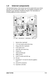
... empty optical drive bay 3. Hard disk drive metal tray 6. ASUS motherboard 8. PCI slot 11. Expansion card slots ASUS T2-PH2 1-9 Proceed to Chapter 2 for your reference. 1.5 Internal components The illustration below is the internal view of the system when you remove the top cover and the power supply unit. DIMM sockets 9. Floppy disk drive (optional) 4. Chassis...
... empty optical drive bay 3. Hard disk drive metal tray 6. ASUS motherboard 8. PCI slot 11. Expansion card slots ASUS T2-PH2 1-9 Proceed to Chapter 2 for your reference. 1.5 Internal components The illustration below is the internal view of the system when you remove the top cover and the power supply unit. DIMM sockets 9. Floppy disk drive (optional) 4. Chassis...

T2-PH2 User''s Manual for English Edition
Page 22
...you plan to install in the system. 2.1 Preparation Before you proceed, make sure that the standby power LED is ON, in sleep mode or in the bag that came with an onboard standby power LED. Basic components to avoid touching the ICs on them. • Whenever you uninstall any system... Use a grounded wrist strap or touch a safely grounded object or a metal object, such as the power supply case, before installing any component, place it on a grounded antistatic pad or in soft-off mode, and not powered OFF. This LED lights up to indicate that the system is OFF before handling components to...
...you plan to install in the system. 2.1 Preparation Before you proceed, make sure that the standby power LED is ON, in sleep mode or in the bag that came with an onboard standby power LED. Basic components to avoid touching the ICs on them. • Whenever you uninstall any system... Use a grounded wrist strap or touch a safely grounded object or a metal object, such as the power supply case, before installing any component, place it on a grounded antistatic pad or in soft-off mode, and not powered OFF. This LED lights up to indicate that the system is OFF before handling components to...
T2-PH2 User''s Manual for English Edition
Page 24
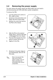
... about half an inch. 6. Slide the PSU as the zoomed image shows, until the side hook is disengaged from the chassis. 5. 2.4 Removing the power supply You must remove the power supply unit (PSU) before you can install a central processing unit (CPU) and other system components. 4 6 5 7 7 2-4 Chapter 2: Basic installation Remove the screw that secures the...
... about half an inch. 6. Slide the PSU as the zoomed image shows, until the side hook is disengaged from the chassis. 5. 2.4 Removing the power supply You must remove the power supply unit (PSU) before you can install a central processing unit (CPU) and other system components. 4 6 5 7 7 2-4 Chapter 2: Basic installation Remove the screw that secures the...
T2-PH2 User''s Manual for English Edition
Page 38
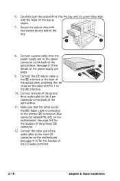
... at the back of the optical drive, matching the red stripe on the cable with Pin 1 on the motherboard. Connect a power cable from the power supply unit to the 4-pin connector at the back of the optical drive. Connect the IDE ribbon cable to the IDE interface at the back of .... See page 4-10 for the location of the CD audio connector. 8 10 9 2-18 Chapter 2: Basic installation Secure the optical drive with the holes on the power supply unit plugs. 9. Make sure that the other end of the optical drive. 11.
... at the back of the optical drive, matching the red stripe on the cable with Pin 1 on the motherboard. Connect a power cable from the power supply unit to the 4-pin connector at the back of the optical drive. Connect the IDE ribbon cable to the IDE interface at the back of .... See page 4-10 for the location of the CD audio connector. 8 10 9 2-18 Chapter 2: Basic installation Secure the optical drive with the holes on the power supply unit plugs. 9. Make sure that the other end of the optical drive. 11.

T2-PH2 User''s Manual for English Edition
Page 40
...the holes on the motherboard. Connect the other end of the signal cable to the power connector at the back of the drive. 5. Remove the front panel cover. For instructions on the power supply unit plugs. 6 4 2-20 Chapter 2: Basic installation Secure the floppy disk... drive with one 3.25-inch drive bay for a floppy disk drive. Connect a power cable from the power supply unit to the floppy disk drive connector (labeled FLOPPY) on the bay. 3. 2.9 Installing a floppy disk drive The barebone ...
...the holes on the motherboard. Connect the other end of the signal cable to the power connector at the back of the drive. 5. Remove the front panel cover. For instructions on the power supply unit plugs. 6 4 2-20 Chapter 2: Basic installation Secure the floppy disk... drive with one 3.25-inch drive bay for a floppy disk drive. Connect a power cable from the power supply unit to the floppy disk drive connector (labeled FLOPPY) on the bay. 3. 2.9 Installing a floppy disk drive The barebone ...
T2-PH2 User''s Manual for English Edition
Page 42
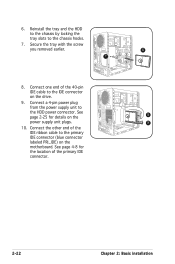
... 4-8 for details on the motherboard. Reinstall the tray and the HDD to the chassis by locking the tray slots to the HDD power connector. Connect a 4-pin power plug from the power supply unit to the chassis hooks. 7. Connect one end of the primary IDE connector. 2-22 Chapter 2: Basic installation See page 2-25 ...for the location of the 40-pin IDE cable to the primary IDE connector (blue connector labeled PRI_IDE) on the 8 power supply unit plugs. 9 10. Connect the other end of the IDE ribbon cable to the IDE connector on the drive. 9.
... 4-8 for details on the motherboard. Reinstall the tray and the HDD to the chassis by locking the tray slots to the HDD power connector. Connect a 4-pin power plug from the power supply unit to the chassis hooks. 7. Connect one end of the primary IDE connector. 2-22 Chapter 2: Basic installation See page 2-25 ...for the location of the 40-pin IDE cable to the primary IDE connector (blue connector labeled PRI_IDE) on the 8 power supply unit plugs. 9 10. Connect the other end of the IDE ribbon cable to the IDE connector on the drive. 9.
T2-PH2 User''s Manual for English Edition
Page 43
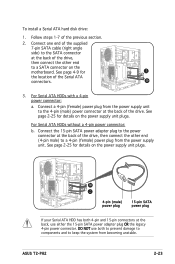
... 2 the location of the drive. DO NOT use either the 15-pin SATA power adapter plug OR the legacy 4-pin power connector. ASUS T2-PH2 2-23 See page 2-25 for details on the motherboard. Connect a 4-pin (female) power plug from the power supply unit to the power connector at the back of the Serial ATA connectors. 3a 3. Connect the...
... 2 the location of the drive. DO NOT use either the 15-pin SATA power adapter plug OR the legacy 4-pin power connector. ASUS T2-PH2 2-23 See page 2-25 for details on the motherboard. Connect a 4-pin (female) power plug from the power supply unit to the power connector at the back of the Serial ATA connectors. 3a 3. Connect the...

T2-PH2 User''s Manual for English Edition
Page 44
2.11 Reinstalling the power supply unit Reinstall the power supply unit (PSU) after installing the system components and reconnecting the cables. Connect the 4-pin 12 V power plug to the ATXPWR connector on the motherboard. 2. Position the PSU over the chassis. 4. Connect the 24-pin ATX power plug to the ... and/or chassis fans. 6 2-24 Chapter 2: Basic installation Align the PSU side hook with the 4 3 metal slot located on the side of power connectors. 2 1 3. See page 4-7 for the location of the optical drive bay. 5. To reinstall the PSU: 1. Make sure the PSU cables...
2.11 Reinstalling the power supply unit Reinstall the power supply unit (PSU) after installing the system components and reconnecting the cables. Connect the 4-pin 12 V power plug to the ATXPWR connector on the motherboard. 2. Position the PSU over the chassis. 4. Connect the 24-pin ATX power plug to the ... and/or chassis fans. 6 2-24 Chapter 2: Basic installation Align the PSU side hook with the 4 3 metal slot located on the side of power connectors. 2 1 3. See page 4-7 for the location of the optical drive bay. 5. To reinstall the PSU: 1. Make sure the PSU cables...

T2-PH2 User''s Manual for English Edition
Page 45
... your area. See the Appendix for the power supply specifications. ASUS T2-PH2 2-25 For Serial ATA hard disk drive without a 4-pin power plug, connect the 15-pin SATA power adapter plug to a 4-pin (female) power plug from the power supply unit. Connect the 4-pin power plug(s) to the power connector of the drive, then connect the other end (4-pin...
... your area. See the Appendix for the power supply specifications. ASUS T2-PH2 2-25 For Serial ATA hard disk drive without a 4-pin power plug, connect the 15-pin SATA power adapter plug to a 4-pin (female) power plug from the power supply unit. Connect the 4-pin power plug(s) to the power connector of the drive, then connect the other end (4-pin...
T2-PH2 User''s Manual for English Edition
Page 65
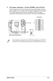
... to connect the 4-pin ATX12V power plug to fit these connectors in only one orientation. ASUS T2-PH2 4-7 The plugs from the power supply unit. otherwise, the system will not boot up. ATX power connectors (24-pin ATXPWR, 4-pin ATX12V) These connectors are for the 24-pin and 4-pin power plugs from the power supply unit are designed to the...
... to connect the 4-pin ATX12V power plug to fit these connectors in only one orientation. ASUS T2-PH2 4-7 The plugs from the power supply unit. otherwise, the system will not boot up. ATX power connectors (24-pin ATXPWR, 4-pin ATX12V) These connectors are for the 24-pin and 4-pin power plugs from the power supply unit are designed to the...

T2-PH2 User''s Manual for English Edition
Page 71
...(2-pin PLED) This 2-pin connector is ON turns the system OFF. 3. Refer to the HDD. • Power/Soft-off button (1-pin PWR) This connector is for the system power button. Pressing the power button turns the system ON or puts the system in sleep mode. • Hard disk drive activity (2-pin ... blinks when the system is read from or written to the section "10. Front panel daughterboard PLED HDLED * Requires an ATX power supply. ASUS T2-PH2 4-13 The IDE LED lights up when you turn on the BIOS settings. PWR PANEL PWR+ GND NC PLED+ PLEDHDLED+ HDLED- Panel connector (8-1 ...
...(2-pin PLED) This 2-pin connector is ON turns the system OFF. 3. Refer to the HDD. • Power/Soft-off button (1-pin PWR) This connector is for the system power button. Pressing the power button turns the system ON or puts the system in sleep mode. • Hard disk drive activity (2-pin ... blinks when the system is read from or written to the section "10. Front panel daughterboard PLED HDLED * Requires an ATX power supply. ASUS T2-PH2 4-13 The IDE LED lights up when you turn on the BIOS settings. PWR PANEL PWR+ GND NC PLED+ PLEDHDLED+ HDLED- Panel connector (8-1 ...

T2-PH2 User''s Manual for English Edition
Page 104
...Configuration options: [Disabled] [Enabled] 5-32 Chapter 5: BIOS setup This feature requires an ATX power supply that provides at least 1A on the +5VSB lead. Configuration options: [Disabled] [Enabled] Power On By PS/2 Keyboard [Disabled] Allows you to use the PS/2 mouse to turn on the system.... This feature requires an ATX power supply that provides at least 1A on the +5VSB lead. Configuration options: [Disabled] [Space Bar] [Ctrl-Esc] [Power Key] Power On By PS/2 Mouse [Disabled] When set to [Enabled], this parameter allows ...
...Configuration options: [Disabled] [Enabled] 5-32 Chapter 5: BIOS setup This feature requires an ATX power supply that provides at least 1A on the +5VSB lead. Configuration options: [Disabled] [Enabled] Power On By PS/2 Keyboard [Disabled] Allows you to use the PS/2 mouse to turn on the system.... This feature requires an ATX power supply that provides at least 1A on the +5VSB lead. Configuration options: [Disabled] [Space Bar] [Ctrl-Esc] [Power Key] Power On By PS/2 Mouse [Disabled] When set to [Enabled], this parameter allows ...
T2-PH2 User''s Manual for English Edition
Page 113
MODE ASUS T2-PH2 Appendix Appendix The Appendix includes the power supply unit specification for this system.
MODE ASUS T2-PH2 Appendix Appendix The Appendix includes the power supply unit specification for this system.
T2-PH2 User''s Manual for English Edition
Page 114
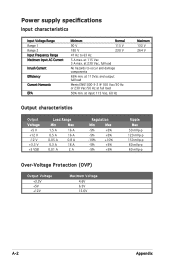
...-p 60 mVp-p 60 mVp-p Over-Voltage Protection (OVP) Output Voltage +3.3V +5V +12V Maximum Voltage 4.6V 6.5V 15.6V A-2 Appendix at full load 50% min. Power supply specifications Input characteristics Input Voltage Range Range 1 Range 2 Input Frequency Range Maximum Input AC Current Inrush Current Efficiency Current Harmonic EPA...
...-p 60 mVp-p 60 mVp-p Over-Voltage Protection (OVP) Output Voltage +3.3V +5V +12V Maximum Voltage 4.6V 6.5V 15.6V A-2 Appendix at full load 50% min. Power supply specifications Input characteristics Input Voltage Range Range 1 Range 2 Input Frequency Range Maximum Input AC Current Inrush Current Efficiency Current Harmonic EPA...