
User Guide
Page 4
... ball-bearing rail kit items 3-5 3.2.1 Attaching the rails to the server 3-5 3.2.2 Attaching the rack rails 3-6 3.2.3 Mounting the server to the rack 3-7 Chapter 4: Motherboard Info 4.1 Motherboard layout 4-2 4.2 Jumpers 4-4 4.3 Internal connectors 4-7 4.4 Internal LEDs 4-19 Chapter 5: BIOS setup 5.1 Managing and updating your BIOS 5-2 5.1.1 ASUS CrashFree BIOS 3 utility 5-2 5.1.2 ASUS EzFlash Utility 5-3 5.1.3 BUPDATER utility 5-4 5.2 BIOS setup program 5-6 5.2.1 BIOS menu...
... ball-bearing rail kit items 3-5 3.2.1 Attaching the rails to the server 3-5 3.2.2 Attaching the rack rails 3-6 3.2.3 Mounting the server to the rack 3-7 Chapter 4: Motherboard Info 4.1 Motherboard layout 4-2 4.2 Jumpers 4-4 4.3 Internal connectors 4-7 4.4 Internal LEDs 4-19 Chapter 5: BIOS setup 5.1 Managing and updating your BIOS 5-2 5.1.1 ASUS CrashFree BIOS 3 utility 5-2 5.1.2 ASUS EzFlash Utility 5-3 5.1.3 BUPDATER utility 5-4 5.2 BIOS setup program 5-6 5.2.1 BIOS menu...

User Guide
Page 5
...) Configuration 5-16 5.4.5 PCI Subsystem Settings 5-18 5.4.6 USB Configuration 5-20 5.4.7 TPM 5-21 5.4.8 ACPI Settings 5-21 5.4.9 WHEA Support 5-22 5.4.10 NCT6779D Super IO Configuration 5-22 5.4.11 Intel Server Platform Services 5-23 5.4.12 Onboard LAN Configuration 5-24 5.4.13 MIO Card Configuration 5-24 5.4.14 Serial Port Console Redirection 5-25 5.4.15 Runtime Error Logging Support 5-27...
...) Configuration 5-16 5.4.5 PCI Subsystem Settings 5-18 5.4.6 USB Configuration 5-20 5.4.7 TPM 5-21 5.4.8 ACPI Settings 5-21 5.4.9 WHEA Support 5-22 5.4.10 NCT6779D Super IO Configuration 5-22 5.4.11 Intel Server Platform Services 5-23 5.4.12 Onboard LAN Configuration 5-24 5.4.13 MIO Card Configuration 5-24 5.4.14 Serial Port Console Redirection 5-25 5.4.15 Runtime Error Logging Support 5-27...

User Guide
Page 8
...broken, do not try to avoid electrical shock. Replace only with a three-wire power cable and plug for the user's safety. This server system is incorrectly replaced. If possible, disconnect all power cables from connectors, slots, sockets and circuitry. • Avoid dust, humidity, and... operation on a stable surface. If any additional devices to the manufacturer's instructions. Use the power cable with the server package. • Before using the server, ensure all cables are correctly connected and the power cables are not damaged. Dispose of explosion if battery is heavy...
...broken, do not try to avoid electrical shock. Replace only with a three-wire power cable and plug for the user's safety. This server system is incorrectly replaced. If possible, disconnect all power cables from connectors, slots, sockets and circuitry. • Avoid dust, humidity, and... operation on a stable surface. If any additional devices to the manufacturer's instructions. Use the power cable with the server package. • Before using the server, ensure all cables are correctly connected and the power cables are not damaged. Dispose of explosion if battery is heavy...

User Guide
Page 10
...Chapter 7: Driver installation This chapter provides instructions for installing the necessary drivers for system integrators, and experienced users with the server. This chapter includes the motherboard layout, jumper settings, and connector locations. 5. Chapter 6: RAID configuration This chapter tells...Chapter 4: Motherboard information This chapter gives information about the motherboard that you have to install optional components into the barebone server. 4. Contents This guide contains the following parts: 1. Chapter 2: Hardware setup This chapter lists the hardware setup procedures...
...Chapter 7: Driver installation This chapter provides instructions for installing the necessary drivers for system integrators, and experienced users with the server. This chapter includes the motherboard layout, jumper settings, and connector locations. 5. Chapter 6: RAID configuration This chapter tells...Chapter 4: Motherboard information This chapter gives information about the motherboard that you have to install optional components into the barebone server. 4. Contents This guide contains the following parts: 1. Chapter 2: Hardware setup This chapter lists the hardware setup procedures...

User Guide
Page 11
NOTE: Tips and additional information to complete a task. Typography Bold text Italics + IMPORTANT: Instructions that you complete a task. DANGER/WARNING: Information to prevent injury to yourself when trying to complete a task. CAUTION: Information to prevent damage to the components when trying to complete a task. Conventions To ensure that you MUST follow to help you perform certain tasks properly, take note of the following symbols used throughout this manual.
NOTE: Tips and additional information to complete a task. Typography Bold text Italics + IMPORTANT: Instructions that you complete a task. DANGER/WARNING: Information to prevent injury to yourself when trying to complete a task. CAUTION: Information to prevent damage to the components when trying to complete a task. Conventions To ensure that you MUST follow to help you perform certain tasks properly, take note of the following symbols used throughout this manual.

User Guide
Page 14
1.1 System package contents Check your system package for the following items. Model Name RS300-E8-PS4, RS300-E8-RS4 Chassis ASUS R10E 1U Rackmount Chassis Motherboard ASUS P9D-C/4L Server Board Component 1 x 400W Single Power Supply (RS300-E8-PS4) 1 x 450W Redundant Power Supply (RS300-E8-RS4) 4 x Hot-swap 3.5" HDD trays 1 x SAS/SATA Backplane (BP4LX-R10A) 1 x PCI Riser Card (RE16LE8R-R10A) 1 x Front I/O Board (FPB-R20D...
1.1 System package contents Check your system package for the following items. Model Name RS300-E8-PS4, RS300-E8-RS4 Chassis ASUS R10E 1U Rackmount Chassis Motherboard ASUS P9D-C/4L Server Board Component 1 x 400W Single Power Supply (RS300-E8-PS4) 1 x 450W Redundant Power Supply (RS300-E8-RS4) 4 x Hot-swap 3.5" HDD trays 1 x SAS/SATA Backplane (BP4LX-R10A) 1 x PCI Riser Card (RE16LE8R-R10A) 1 x Front I/O Board (FPB-R20D...
User Guide
Page 16
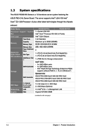
... SSI Location #) Additional Slot 1 Storage SATA Controller SAS Controller HDD Bays Networking Graphic I = internal A or S = hotswappable LAN VGA RS300-E8-PS4, RS300-E8-RS4 1 x Socket LGA1150 Intel® Xeon® Processor E3-1200 v3 Family Intel® C224 Chipset 4 (2 Channels) Maximum up ... 2308 8-port SAS 6G RAID Card 4 x Hot-swap 3.5 in. 1.3 System specifications The ASUS RS300-E8 Series is a 1U barebone server system featuring the ASUS P9D-C/4L Server Board. The server supports Intel® LGA1150 Intel® Xeon® E3-1200 Processor v3 plus other latest technologies ...
... SSI Location #) Additional Slot 1 Storage SATA Controller SAS Controller HDD Bays Networking Graphic I = internal A or S = hotswappable LAN VGA RS300-E8-PS4, RS300-E8-RS4 1 x Socket LGA1150 Intel® Xeon® Processor E3-1200 v3 Family Intel® C224 Chipset 4 (2 Channels) Maximum up ... 2308 8-port SAS 6G RAID Card 4 x Hot-swap 3.5 in. 1.3 System specifications The ASUS RS300-E8 Series is a 1U barebone server system featuring the ASUS P9D-C/4L Server Board. The server supports Intel® LGA1150 Intel® Xeon® E3-1200 Processor v3 plus other latest technologies ...

User Guide
Page 17
...Supply Power Rating Environment RS300-E8-PS4 RS300-E8-RS4 1 x External Serial Port 5 x RJ-45 ports (1 for ASMB7-iKVM) 4 x USB 3.0 ports (Front x 2, Rear x 2) 2 x USB 2.0 ports (Rear x 2) 2 x VGA port (Front x 1, Rear x 1) 1 x Internal A-Type USB Port 1 x PS/2 keyboard/mouse combo port Windows® Server 2012 Windows® 8 64-bit Windows® Server 2008 Enterprise SP2 64... temperature: 10oC - 40oC Non operation temperature: -40oC - 70oC Non operation humidity: 20% - 90% (Non condensing) *Specifications are subject to change without notice. ASUS RS300-E8 Series 1-5
...Supply Power Rating Environment RS300-E8-PS4 RS300-E8-RS4 1 x External Serial Port 5 x RJ-45 ports (1 for ASMB7-iKVM) 4 x USB 3.0 ports (Front x 2, Rear x 2) 2 x USB 2.0 ports (Rear x 2) 2 x VGA port (Front x 1, Rear x 1) 1 x Internal A-Type USB Port 1 x PS/2 keyboard/mouse combo port Windows® Server 2012 Windows® 8 64-bit Windows® Server 2008 Enterprise SP2 64... temperature: 10oC - 40oC Non operation temperature: -40oC - 70oC Non operation humidity: 20% - 90% (Non condensing) *Specifications are subject to change without notice. ASUS RS300-E8 Series 1-5

User Guide
Page 18
... but useful device that you to write down important information about to section 1.7.1 Front panel LEDs for the LED descriptions. 1.4 Front panel features The barebone server displays a simple yet stylish front panel with easily accessible features. Rack screw Hot-swap HDD bays Hot-swap HDD bays Rack screw Slim-type optical...
... but useful device that you to write down important information about to section 1.7.1 Front panel LEDs for the LED descriptions. 1.4 Front panel features The barebone server displays a simple yet stylish front panel with easily accessible features. Rack screw Hot-swap HDD bays Hot-swap HDD bays Rack screw Slim-type optical...

User Guide
Page 20
ASUS P9D-C/4L Server Boards 4. The barebone server does not include a floppy disk drive drive. SSD Cage (Optional) 13. Slim-type optical drive 12. 1.6 Internal features The barebone server includes the basic components as shown. 2 1 3 12 4 444 5 6 7 8 9 11 123 10 1. SAS / SATA backplane (hidden) 6. HDD tray 2-Connect to SATA1 port 7. PCI Express slot Riser ...
ASUS P9D-C/4L Server Boards 4. The barebone server does not include a floppy disk drive drive. SSD Cage (Optional) 13. Slim-type optical drive 12. 1.6 Internal features The barebone server includes the basic components as shown. 2 1 3 12 4 444 5 6 7 8 9 11 123 10 1. SAS / SATA backplane (hidden) 6. HDD tray 2-Connect to SATA1 port 7. PCI Express slot Riser ...

User Guide
Page 29
Secure the heat pipe and air duct to the server with two screws. 5. Insert the two tips of the system fan mylar into the CPU heatsink, as shown in the right figure. ASUS RS300-E8 Series 2-7 4.
Secure the heat pipe and air duct to the server with two screws. 5. Insert the two tips of the system fan mylar into the CPU heatsink, as shown in the right figure. ASUS RS300-E8 Series 2-7 4.

User Guide
Page 34
... surface, then remove the screw from the PCI Express x16 slot on the motherboard. 2. Repeat the previous steps to the riser card bracket The barebone server comes with a screw. 4. You need to remove the bracket if you want to install PCI Express x8 or x16 expansion cards.
... surface, then remove the screw from the PCI Express x16 slot on the motherboard. 2. Repeat the previous steps to the riser card bracket The barebone server comes with a screw. 4. You need to remove the bracket if you want to install PCI Express x8 or x16 expansion cards.

User Guide
Page 42
LAN port 5 LAN port 1 2-20 Chapter 2: Hardware setup Orient and press the ASMB7 management card in place. 3. Locate the ASMB7 header on your motherboard. 1. Insert the LAN cable plug to install an optional ASMB7 series management board on the motherboard. 2. 2.8.3 Installing ASMB7 series management board (optional) Follow the steps below to the LAN port 5 (dedicated LAN) or LAN port 1 (shared LAN) for server management.
LAN port 5 LAN port 1 2-20 Chapter 2: Hardware setup Orient and press the ASMB7 management card in place. 3. Locate the ASMB7 header on your motherboard. 1. Insert the LAN cable plug to install an optional ASMB7 series management board on the motherboard. 2. 2.8.3 Installing ASMB7 series management board (optional) Follow the steps below to the LAN port 5 (dedicated LAN) or LAN port 1 (shared LAN) for server management.

User Guide
Page 43
... the optional SSD cage on your server module. 1. With the SSD cage resting on the side of the SSD cage. 2. Secure the SSD card into the SSD cage. 3. 2.8.4 Installing the SSD cage (optional) Follow the steps below to the SSD card. SATA Power cable SATA connector ASUS RS300-E8 Series 2-21 Lift the SSD...
... the optional SSD cage on your server module. 1. With the SSD cage resting on the side of the SSD cage. 2. Secure the SSD card into the SSD cage. 3. 2.8.4 Installing the SSD cage (optional) Follow the steps below to the SSD card. SATA Power cable SATA connector ASUS RS300-E8 Series 2-21 Lift the SSD...

User Guide
Page 44
Secure the SDD cage to the onboard SATA connectors 7. to the server module using the bundled screws. 6. Connect the Power cable to the connector on the motherboard. 2-22 Chapter 2: Hardware setup 5. Connect the SATA cable connector.
Secure the SDD cage to the onboard SATA connectors 7. to the server module using the bundled screws. 6. Connect the Power cable to the connector on the motherboard. 2-22 Chapter 2: Hardware setup 5. Connect the SATA cable connector.

User Guide
Page 45
Installation options Chapter 3 This chapter describes how to install the optional components and devices into the barebone server. 2-
Installation options Chapter 3 This chapter describes how to install the optional components and devices into the barebone server. 2-

User Guide
Page 46
... manual for each buffer) Rail Washers Latch screws Rail screws Front end Fixing latches Rack rails Rear end 3.1.1 Attaching the fixing latches to the server 1. Fixing latch The locations of fixing latches • 4 latch screws, 4 rail screws and 4 rail washers (2 more for details. 3-2 Chapter 3: Installation options 3.1 Friction Rail Kit Installation ...
... manual for each buffer) Rail Washers Latch screws Rail screws Front end Fixing latches Rack rails Rear end 3.1.1 Attaching the fixing latches to the server 1. Fixing latch The locations of fixing latches • 4 latch screws, 4 rail screws and 4 rail washers (2 more for details. 3-2 Chapter 3: Installation options 3.1 Friction Rail Kit Installation ...

User Guide
Page 48
DO NOT install the rail to include the side knots on the two sides of the server in the rack rail holders, as shown in the following situation: DO NOT place the rail hook on a thick lip of the server rack. 3-4 Chapter 3: Installation options When mounting the server to the rack, ensure to the outer side of the mounting hole. 7. Do not install the rail kit in the right figure.
DO NOT install the rail to include the side knots on the two sides of the server in the rack rail holders, as shown in the following situation: DO NOT place the rail hook on a thick lip of the server rack. 3-4 Chapter 3: Installation options When mounting the server to the rack, ensure to the outer side of the mounting hole. 7. Do not install the rail kit in the right figure.

User Guide
Page 70
This LED helps you visually locate the server among other servers especially when you are located at the back of the server rack. 4-22 Chapter 4: Motherboard information Location LED (LOCLED1) The Location LED is an onboard LED that ligths up when the Location Button on the front panel is pressed. 5.
This LED helps you visually locate the server among other servers especially when you are located at the back of the server rack. 4-22 Chapter 4: Motherboard information Location LED (LOCLED1) The Location LED is an onboard LED that ligths up when the Location Button on the front panel is pressed. 5.

User Guide
Page 93
... NM FW Status Value : 0x80000001 BIOS Booting Mode : Power Optimized Mode Cores Disabled : 0 ME FW SKU Information : Node Manager End-of the Intel Server Platform Services configured in POST ASUS RS300-E8 Series 5-23 Configuration options: [Auto] [IO=378h; Configuration options: [STD Printer mode] [SPP Mode] [EPP-1.9 and SPP Mode] [EPP-1.7 and SPP Mode...
... NM FW Status Value : 0x80000001 BIOS Booting Mode : Power Optimized Mode Cores Disabled : 0 ME FW SKU Information : Node Manager End-of the Intel Server Platform Services configured in POST ASUS RS300-E8 Series 5-23 Configuration options: [Auto] [IO=378h; Configuration options: [STD Printer mode] [SPP Mode] [EPP-1.9 and SPP Mode] [EPP-1.7 and SPP Mode...
