
User Guide
Page 6
...disconnect all power cables from the existing system before you add a device. • Before connecting or removing signal cables from connectors, slots, sockets and circuitry. • Avoid dust, humidity, and temperature extremes. If you are not sure about the voltage of the electrical outlet you... you detect any damage, contact your dealer immediately. • To avoid short circuits, keep paper clips, screws, and staples away from the motherboard, ensure that came with the product, contact a qualified service technician or your retailer. Do not place the product in your area. If you...
...disconnect all power cables from the existing system before you add a device. • Before connecting or removing signal cables from connectors, slots, sockets and circuitry. • Avoid dust, humidity, and temperature extremes. If you are not sure about the voltage of the electrical outlet you... you detect any damage, contact your dealer immediately. • To avoid short circuits, keep paper clips, screws, and staples away from the motherboard, ensure that came with the product, contact a qualified service technician or your retailer. Do not place the product in your area. If you...

User Guide
Page 9
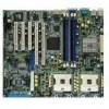
PCH-DR specifications summary CPU Chipset Front Side Bus (FSB) Memory Expansion slots Storage LAN Rear panel I/O Internal connectors Dual 604-pin sockets for Intel® Xeon™ Processors 3.2GHz with Hyper-Threding Technology On-die 1MB/512KB L2 cache North bridge: Intel® E7210 Memory ...Controller Hub (MCH) South bridge: Intel® 6300ESB I/O Controller Hub (ICH) 533/400 MHz Dual-channel memory architecture 4 x 184-pin DDR DIMM sockets for up to 4GB memory Supports PC2700/PC2100 unbuffered ECC or non-ECC DDR DIMMs 2 x 3.3V/64-bit/66MHz PCI-X 3 x 5V/32-bit/33MHz PCI...
PCH-DR specifications summary CPU Chipset Front Side Bus (FSB) Memory Expansion slots Storage LAN Rear panel I/O Internal connectors Dual 604-pin sockets for Intel® Xeon™ Processors 3.2GHz with Hyper-Threding Technology On-die 1MB/512KB L2 cache North bridge: Intel® E7210 Memory ...Controller Hub (MCH) South bridge: Intel® 6300ESB I/O Controller Hub (ICH) 533/400 MHz Dual-channel memory architecture 4 x 184-pin DDR DIMM sockets for up to 4GB memory Supports PC2700/PC2100 unbuffered ECC or non-ECC DDR DIMMs 2 x 3.3V/64-bit/66MHz PCI-X 3 x 5V/32-bit/33MHz PCI...

User Guide
Page 14
...deliver up to 5.33GB/s data transfer rate for thinner, more flexible cables with USB 1.1. 1-2 Chapter 1: Product introduction USB 2.0 technology The motherboard implements the Universal Serial Bus (USB) 2.0 specification, dramatically increasing the connection speed from the 12 Mbps bandwidth on USB 1.1 to 150MB/s... data transfer rate. 1.3 Special features Latest processor technology The motherboard supports dual Intel® Xeon™ Processors via 604-pin surface mount ZIF sockets. The processor has 1MB/512KB L2 cache, includes a 533/400MHz system bus, and ...
...deliver up to 5.33GB/s data transfer rate for thinner, more flexible cables with USB 1.1. 1-2 Chapter 1: Product introduction USB 2.0 technology The motherboard implements the Universal Serial Bus (USB) 2.0 specification, dramatically increasing the connection speed from the 12 Mbps bandwidth on USB 1.1 to 150MB/s... data transfer rate. 1.3 Special features Latest processor technology The motherboard supports dual Intel® Xeon™ Processors via 604-pin surface mount ZIF sockets. The processor has 1MB/512KB L2 cache, includes a 533/400MHz system bus, and ...

User Guide
Page 19
... PCH-DR PCH-DR Onboard LED ON Standby Power OFF Powered Off ASUS PCH-DR motherboard 2-1 Whenever you uninstall any component, place it on this motherboard. You must install identical CPUs on a grounded antistatic pad or in the bag that the ATX power supply is detached from the wall socket ...came with the component. 5. This warning LED (LED1) lights up if you install motherboard components or change any motherboard component. Failure to do so may cause severe damage to the motherboard, peripherals, and/or components. Unplug the power cord from the power supply. When ...
... PCH-DR PCH-DR Onboard LED ON Standby Power OFF Powered Off ASUS PCH-DR motherboard 2-1 Whenever you uninstall any component, place it on this motherboard. You must install identical CPUs on a grounded antistatic pad or in the bag that the ATX power supply is detached from the wall socket ...came with the component. 5. This warning LED (LED1) lights up if you install motherboard components or change any motherboard component. Failure to do so may cause severe damage to the motherboard, peripherals, and/or components. Unplug the power cord from the power supply. When ...

User Guide
Page 22
...22 8. Onboard VGA setting (3-pin VGA_EN1) 2-22 9. USB 2.0 ports 1 and 2 2-24 4. Floppy disk drive connector (34-1 pin FLOPPY1) 2-25 2. CPU sockets 2. PCI/PCI-X slots Page 2-6 2-13 2-18 Jumpers 1. Keyboard power (3-pin KBPWR1) 2-19 2. RAID ATA/133/100/66/33 connector (40-1 pin PRI_RAID1) ...2-24 2. Backplane SMBus connector (6-1 pin BPSMB1) 2-26 5. Gigabit LAN1 controller setting (3-pin LAN_EN1) 2-21 6. 2.2.4 Layout Contents Sockets/Slots 1. DDR DIMM sockets 3. RAID enable (3-pin RAID_EN1) 2-20 5. Serial ATA connectors (7-pin SATA1, SATA2) 2-25 3.
...22 8. Onboard VGA setting (3-pin VGA_EN1) 2-22 9. USB 2.0 ports 1 and 2 2-24 4. Floppy disk drive connector (34-1 pin FLOPPY1) 2-25 2. CPU sockets 2. PCI/PCI-X slots Page 2-6 2-13 2-18 Jumpers 1. Keyboard power (3-pin KBPWR1) 2-19 2. RAID ATA/133/100/66/33 connector (40-1 pin PRI_RAID1) ...2-24 2. Backplane SMBus connector (6-1 pin BPSMB1) 2-26 5. Gigabit LAN1 controller setting (3-pin LAN_EN1) 2-21 6. 2.2.4 Layout Contents Sockets/Slots 1. DDR DIMM sockets 3. RAID enable (3-pin RAID_EN1) 2-20 5. Serial ATA connectors (7-pin SATA1, SATA2) 2-25 3.

User Guide
Page 24
... stability.. Intel Xeon Gold Arrow Pin A1 PCH-DR PCH-DR CPU Socket 604 2.3.2 Installing the CPU Note in the 604-pin package with dual surface mount 604-pin Zero Insertion Force (ZIF) sockets. The sockets are designed for CPU1 2-6 Chapter 2: Hardware information If installing only one corner. Socket for CPU2 Socket for the Intel® Xeon™ Processor...
... stability.. Intel Xeon Gold Arrow Pin A1 PCH-DR PCH-DR CPU Socket 604 2.3.2 Installing the CPU Note in the 604-pin package with dual surface mount 604-pin Zero Insertion Force (ZIF) sockets. The sockets are designed for CPU1 2-6 Chapter 2: Hardware information If installing only one corner. Socket for CPU2 Socket for the Intel® Xeon™ Processor...

User Guide
Page 25
...fits only in one correct orientation. Carefully push down the socket lever to install a CPU. 1. This thermal grease should come with the CPU package. Position the CPU above the socket as shown. 3. ASUS PCH-DR motherboard 2-7 Locate the 604-pin ZIF sockets on the side tab to the other side. Marked Corner... 4. Follow these steps to secure the CPU. DO NOT force the CPU into the socket to the top of the CPU...
...fits only in one correct orientation. Carefully push down the socket lever to install a CPU. 1. This thermal grease should come with the CPU package. Position the CPU above the socket as shown. 3. ASUS PCH-DR motherboard 2-7 Locate the 604-pin ZIF sockets on the side tab to the other side. Marked Corner... 4. Follow these steps to secure the CPU. DO NOT force the CPU into the socket to the top of the CPU...

User Guide
Page 26
...steps 1 to the installation manual that came with the CPU package for CPU installation. 1. With the motherboard on a flat stable surface (such as a table), place the thermal plate underneath a CPU socket, matching the standoffs on heatsink/fan assembly and installation. 2.3.3 Installing the CPU heatsink and fan The ... an Intel certified heatsink and fan assembly to the top of the motherboard holes and standoffs. Make sure that are necessary for details on the plate with the four holes around the CPU socket. The figure below shows the corresponding matches of the CPU before installing...
...steps 1 to the installation manual that came with the CPU package for CPU installation. 1. With the motherboard on a flat stable surface (such as a table), place the thermal plate underneath a CPU socket, matching the standoffs on heatsink/fan assembly and installation. 2.3.3 Installing the CPU heatsink and fan The ... an Intel certified heatsink and fan assembly to the top of the motherboard holes and standoffs. Make sure that are necessary for details on the plate with the four holes around the CPU socket. The figure below shows the corresponding matches of the CPU before installing...

User Guide
Page 27
Heatsink angled side ASUS PCH-DR motherboard 2-9 Secure the retention mechanism with the four holes on the motherboard and the standoffs on the thermal plate. Make sure that the heatsink base fits completely on top of the CPU, having its holes with the thermal plate using four screws. 4. 2. Heatsink retention mechanism 3. Place the heatsink retention mechanism over the CPU socket, matching its angled side (with cut corners) facing the memory sockets. Position the heatsink on the retention mechanism.
Heatsink angled side ASUS PCH-DR motherboard 2-9 Secure the retention mechanism with the four holes on the motherboard and the standoffs on the thermal plate. Make sure that the heatsink base fits completely on top of the CPU, having its holes with the thermal plate using four screws. 4. 2. Heatsink retention mechanism 3. Place the heatsink retention mechanism over the CPU socket, matching its angled side (with cut corners) facing the memory sockets. Position the heatsink on the retention mechanism.
User Guide
Page 31
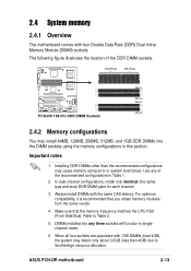
...size) DDR DIMM pairs for each channel. 3. Make sure that you obtain memory modules from the same vendor. 4. ASUS PCH-DR motherboard 2-13 Use any three sockets will function in singlechannel mode. 6. For optimum compatibility, it is recommended that the memory frequency matches the CPU FSB ...installed into any of the DDR DIMM sockets. 104 Pins 80 Pins PCH-DR PCH-DR 184-Pin DDR DIMM Sockets DDR_A1 DDR_A2 DDR_B1 DDR_B2 2.4.2 Memory configurations You may cause memory sizing error or system boot failure. 2.4 System memory 2.4.1 Overview The motherboard comes with the same CAS latency....
...size) DDR DIMM pairs for each channel. 3. Make sure that you obtain memory modules from the same vendor. 4. ASUS PCH-DR motherboard 2-13 Use any three sockets will function in singlechannel mode. 6. For optimum compatibility, it is recommended that the memory frequency matches the CPU FSB ...installed into any of the DDR DIMM sockets. 104 Pins 80 Pins PCH-DR PCH-DR 184-Pin DDR DIMM Sockets DDR_A1 DDR_A2 DDR_B1 DDR_B2 2.4.2 Memory configurations You may cause memory sizing error or system boot failure. 2.4 System memory 2.4.1 Overview The motherboard comes with the same CAS latency....

User Guide
Page 32
...in DDR_A2 and DDR_B2 (black sockets) Table 2 Memory frequency/CPU FSB synchronization CPU FSB 533 MHz 400 MHz DDR DIMM Type PC2700/PC2100 PC2100 Memory Frequency 333/266 MHz 266 MHz Obtain DDR DIMMs only from ASUS qualified vendors for the latest QVL.... 2-14 Chapter 2: Hardware information Populated (1) Populated - Table 1 Recommended memory configurations Mode Single-channel Dual-channel DDR_A1 (blue) Sockets DDR_A2 DDR_B1 (black) (blue) DDR_B2 (black) (1) Populated -...
...in DDR_A2 and DDR_B2 (black sockets) Table 2 Memory frequency/CPU FSB synchronization CPU FSB 533 MHz 400 MHz DDR DIMM Type PC2700/PC2100 PC2100 Memory Frequency 333/266 MHz 266 MHz Obtain DDR DIMMs only from ASUS qualified vendors for the latest QVL.... 2-14 Chapter 2: Hardware information Populated (1) Populated - Table 1 Recommended memory configurations Mode Single-channel Dual-channel DDR_A1 (blue) Sockets DDR_A2 DDR_B1 (black) (blue) DDR_B2 (black) (1) Populated -...

User Guide
Page 33
... the notch on the DIMM matches the break on the socket. DO NOT force a DIMM into the socket until the retaining clips snap back in only one direction. Firmly insert the DIMM into a socket to both the motherboard and the components. Failure to do so may cause severe... damage to avoid damaging the DIMM. 3. Align a DIMM on the socket such that it flips out with your fingers when pressing the retaining clips. ASUS PCH-DR motherboard 2-15
... the notch on the DIMM matches the break on the socket. DO NOT force a DIMM into the socket until the retaining clips snap back in only one direction. Firmly insert the DIMM into a socket to both the motherboard and the components. Failure to do so may cause severe... damage to avoid damaging the DIMM. 3. Align a DIMM on the socket such that it flips out with your fingers when pressing the retaining clips. ASUS PCH-DR motherboard 2-15


