
User Guide
Page 9
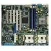
...) Floppy disk drive connector Serial ATA connectors IDE connectors SMBus connector RAID ATA/133/100/66/33 connector Serial ATA RAID connectors Parallel port connector SSI power connectors Mini-PCI connector Serial port 2 connector Power supply SMBus connector CPU and system fan connectors Auxilliary panel connector USB 2.0 connector System panel connector ix PCH-DR specifications summary CPU Chipset Front Side Bus (FSB) Memory Expansion slots Storage LAN Rear panel I/O Internal connectors Dual 604-pin sockets for Intel® Xeon™ Processors 3.2GHz with Hyper-Threding Technology On...
...) Floppy disk drive connector Serial ATA connectors IDE connectors SMBus connector RAID ATA/133/100/66/33 connector Serial ATA RAID connectors Parallel port connector SSI power connectors Mini-PCI connector Serial port 2 connector Power supply SMBus connector CPU and system fan connectors Auxilliary panel connector USB 2.0 connector System panel connector ix PCH-DR specifications summary CPU Chipset Front Side Bus (FSB) Memory Expansion slots Storage LAN Rear panel I/O Internal connectors Dual 604-pin sockets for Intel® Xeon™ Processors 3.2GHz with Hyper-Threding Technology On...
User Guide
Page 13
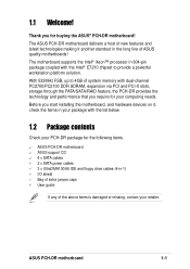
... start installing the motherboard, and hardware devices on it another standout in the long line of system memory with the Intel® E7210 chipset to provide a powerful workstation platform solution. With 533MHz FSB, up to 4GB of ASUS quality motherboards! ASUS PCH-DR motherboard 1-1 1.1 Welcome! Thank you require for buying the ASUS® PCH-DR motherboard! The motherboard supports the Intel® Xeon™ processor in -1) I/O shield Bag of extra jumper caps User guide...
... start installing the motherboard, and hardware devices on it another standout in the long line of system memory with the Intel® E7210 chipset to provide a powerful workstation platform solution. With 533MHz FSB, up to 4GB of ASUS quality motherboards! ASUS PCH-DR motherboard 1-1 1.1 Welcome! Thank you require for buying the ASUS® PCH-DR motherboard! The motherboard supports the Intel® Xeon™ processor in -1) I/O shield Bag of extra jumper caps User guide...

User Guide
Page 19
... in the bag that you install motherboard components or change any motherboard settings. 1. LED1 ON OFF CPU Type/Voltage CPU Type/Voltage not identical identical SB_PWR1 PCH-DR PCH-DR Onboard LED ON Standby Power OFF Powered Off ASUS PCH-DR motherboard 2-1 Unplug the power cord from the power supply. When lit, the green LED (SB_PWR1) indicates that the system is ON, in sleep mode, or in soft-off or the power cord is switched off mode, a reminder that came with the...
... in the bag that you install motherboard components or change any motherboard settings. 1. LED1 ON OFF CPU Type/Voltage CPU Type/Voltage not identical identical SB_PWR1 PCH-DR PCH-DR Onboard LED ON Standby Power OFF Powered Off ASUS PCH-DR motherboard 2-1 Unplug the power cord from the power supply. When lit, the green LED (SB_PWR1) indicates that the system is ON, in sleep mode, or in soft-off or the power cord is switched off mode, a reminder that came with the...

User Guide
Page 22
...USB device wake-up (3-pin USBPW12, USBPW34) 2-20 4. Gigabit LAN1 controller setting (3-pin LAN_EN1) 2-21 6. Onboard VGA setting (3-pin VGA_EN1) 2-22 9. Floppy disk drive connector (34-1 pin FLOPPY1) 2-25 2. RAID ATA/133/100/66/33 connector (40-1 pin PRI_RAID1) 2-27 6. Serial ATA RAID connectors (7-pin SATA_RAID1, SATA_RAID2) 2-28 7. 2.2.4 Layout Contents Sockets/Slots 1. PS/2 keyboard port 2-24 3. USB 2.0 ports 1 and 2 2-24 4. Serial ATA connectors (7-pin SATA1, SATA2) 2-25 3. Keyboard power (3-pin KBPWR1) 2-19 2. Gigabit LAN2 controller setting (3-pin...
...USB device wake-up (3-pin USBPW12, USBPW34) 2-20 4. Gigabit LAN1 controller setting (3-pin LAN_EN1) 2-21 6. Onboard VGA setting (3-pin VGA_EN1) 2-22 9. Floppy disk drive connector (34-1 pin FLOPPY1) 2-25 2. RAID ATA/133/100/66/33 connector (40-1 pin PRI_RAID1) 2-27 6. Serial ATA RAID connectors (7-pin SATA_RAID1, SATA_RAID2) 2-28 7. 2.2.4 Layout Contents Sockets/Slots 1. PS/2 keyboard port 2-24 3. USB 2.0 ports 1 and 2 2-24 4. Serial ATA connectors (7-pin SATA1, SATA2) 2-25 3. Keyboard power (3-pin KBPWR1) 2-19 2. Gigabit LAN2 controller setting (3-pin...
User Guide
Page 34
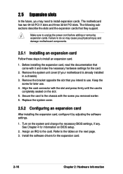
... completely seated on BIOS setup. 2. Align the card connector with the screw you intend to use . 4. Replace the system cover. 2.5.2 Configuring an expansion card After installing the expansion card, configure it and make the necessary hardware settings for later use . Keep the screw for the card. 2. The motherboard has two 64-bit PCI-X slots and three 32-bit PCI slots. Before installing the expansion card, read the documentation that they support. 2.5 Expansion slots In the...
... completely seated on BIOS setup. 2. Align the card connector with the screw you intend to use . 4. Replace the system cover. 2.5.2 Configuring an expansion card After installing the expansion card, configure it and make the necessary hardware settings for later use . Keep the screw for the card. 2. The motherboard has two 64-bit PCI-X slots and three 32-bit PCI slots. Before installing the expansion card, read the documentation that they support. 2.5 Expansion slots In the...

User Guide
Page 35
... Port (COM1) 5* 13 Sound Card (sometimes LPT2) 6 14 Floppy Disk Controller 7* 15 Printer Port (LPT1) 8 3 System CMOS/Real Time Clock 9* 4 ACPI Mode when used 10* 5 IRQ Holder for PCI Steering 11* 6 IRQ Holder for PCI Steering 12* 7 PS/2 Compatible Mouse Port 13 8 Numeric Data Processor 14* 9 Primary IDE Channel 15* 10 Secondary IDE Channel * These IRQs are usually available for this motherboard INTA# INTB# INTC# INTD# PCI slot 1 IRQ_F# PCI slot 2 IRQ_G# PCI slot 3 IRQ_H# PCI-X slot 1 PI_IRQ0# PCI-X slot 2 PI_IRQ1# Onbd. LAN controller...
... Port (COM1) 5* 13 Sound Card (sometimes LPT2) 6 14 Floppy Disk Controller 7* 15 Printer Port (LPT1) 8 3 System CMOS/Real Time Clock 9* 4 ACPI Mode when used 10* 5 IRQ Holder for PCI Steering 11* 6 IRQ Holder for PCI Steering 12* 7 PS/2 Compatible Mouse Port 13 8 Numeric Data Processor 14* 9 Primary IDE Channel 15* 10 Secondary IDE Channel * These IRQs are usually available for this motherboard INTA# INTB# INTC# INTD# PCI slot 1 IRQ_F# PCI slot 2 IRQ_G# PCI slot 3 IRQ_H# PCI-X slot 1 PI_IRQ0# PCI-X slot 2 PI_IRQ1# Onbd. LAN controller...
User Guide
Page 37
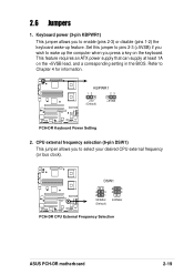
...an ATX power supply that can supply at least 1A on the keyboard. CPU external frequency selection (6-pin DSW1) This jumper allows you press a key on the +5VSB lead, and a corresponding setting in the BIOS. DSW1 4 3 2 1 533MHz (Default) 6 5 4 3 400MHz PCH-DR PCH-DR CPU External Frequency Selection ASUS PCH-DR motherboard 2-19 KBPWR1 12 23 +5V (Default) +5VSB PCH-DR PCH-DR Keyboard Power Setting 2. Refer to enable (pins 2-3) or disable (pins 1-2) the keyboard wake-up the computer when you to select your desired CPU external frequency (or bus clock). Set this...
...an ATX power supply that can supply at least 1A on the keyboard. CPU external frequency selection (6-pin DSW1) This jumper allows you press a key on the +5VSB lead, and a corresponding setting in the BIOS. DSW1 4 3 2 1 533MHz (Default) 6 5 4 3 400MHz PCH-DR PCH-DR CPU External Frequency Selection ASUS PCH-DR motherboard 2-19 KBPWR1 12 23 +5V (Default) +5VSB PCH-DR PCH-DR Keyboard Power Setting 2. Refer to enable (pins 2-3) or disable (pins 1-2) the keyboard wake-up the computer when you to select your desired CPU external frequency (or bus clock). Set this...

User Guide
Page 39
... controller setting (3-pin LAN_EN1) This jumper allows you to pins 2-3 disables the Gigabit LAN port 2 (RJ-45) on the rear panel. 5. Setting this jumper to enable or disable the Intel® 82541GI Gigabit LAN controller. Gigabit LAN2 controller setting (3-pin LAN_EN2) This jumper allows you to pins 2-3 disables the Gigabit LAN port 1 (RJ-45) on the rear panel. PCH-DR PCH-DR LAN_EN2 Setting LAN_EN2 12 23 Enable (Default) Disable ASUS PCH-DR motherboard 2-21 PCH-DR PCH-DR LAN_EN1 Setting LAN_EN1 12 23 Enable (Default) Disable 6. Setting this jumper to enable...
... controller setting (3-pin LAN_EN1) This jumper allows you to pins 2-3 disables the Gigabit LAN port 2 (RJ-45) on the rear panel. 5. Setting this jumper to enable or disable the Intel® 82541GI Gigabit LAN controller. Gigabit LAN2 controller setting (3-pin LAN_EN2) This jumper allows you to pins 2-3 disables the Gigabit LAN port 1 (RJ-45) on the rear panel. PCH-DR PCH-DR LAN_EN2 Setting LAN_EN2 12 23 Enable (Default) Disable ASUS PCH-DR motherboard 2-21 PCH-DR PCH-DR LAN_EN1 Setting LAN_EN1 12 23 Enable (Default) Disable 6. Setting this jumper to enable...

User Guide
Page 40
....EXE utility. 2. PCH-DR PCH-DR VGA Setting VGA_EN1 12 23 Enable (Default) Disable 2-22 Chapter 2: Hardware information Recovery setting (3-pin RECOVERY1) This jumper allows you to update/recover the BIOS quickly. Shut down the system. 5. Onboard VGA setting (3-pin VGA_EN1) This jumper allows you to enable or disable the onboard VGA. 7. Insert the floppy disk then turn on the system. Turn on the system to install a VGA card. Set the jumper to pins 1-2. 6. RECOVERY1 12 23 Normal (Default) PCH-DR PCH-DR BIOS Recovery Setting BIOS Recovery 8. Set the jumper back...
....EXE utility. 2. PCH-DR PCH-DR VGA Setting VGA_EN1 12 23 Enable (Default) Disable 2-22 Chapter 2: Hardware information Recovery setting (3-pin RECOVERY1) This jumper allows you to update/recover the BIOS quickly. Shut down the system. 5. Onboard VGA setting (3-pin VGA_EN1) This jumper allows you to enable or disable the onboard VGA. 7. Insert the floppy disk then turn on the system. Turn on the system to install a VGA card. Set the jumper to pins 1-2. 6. RECOVERY1 12 23 Normal (Default) PCH-DR PCH-DR BIOS Recovery Setting BIOS Recovery 8. Set the jumper back...
User Guide
Page 41
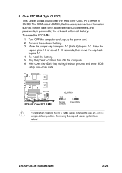
... enter BIOS setup to clear the Real Time Clock (RTC) RAM in CMOS, that include system setup information such as system date, time, and system setup parameters, and passwords, is powered by the onboard button cell battery. Remove the onboard battery. 3. Move the jumper cap from pins 1-2 (default) to pins 1-2. 4. Keep the cap on CLRTC jumper default position. Plug the power cord and turn ON the computer. 6. ASUS PCH-DR motherboard 2-23 Turn OFF the computer and unplug the power cord. 2. PCH-DR PCH-DR Clear RTC RAM...
... enter BIOS setup to clear the Real Time Clock (RTC) RAM in CMOS, that include system setup information such as system date, time, and system setup parameters, and passwords, is powered by the onboard button cell battery. Remove the onboard battery. 3. Move the jumper cap from pins 1-2 (default) to pins 1-2. 4. Keep the cap on CLRTC jumper default position. Plug the power cord and turn ON the computer. 6. ASUS PCH-DR motherboard 2-23 Turn OFF the computer and unplug the power cord. 2. PCH-DR PCH-DR Clear RTC RAM...

User Guide
Page 65
ASUS PCH-DR motherboard 4-7 4.2.1 BIOS menu screen Menu bar Menu items General help Time (hh:mm:ss) Date (mm:dd:yy) Legacy Diskette A Floppy 3 Mode Support Primary IDE Master Primary IDE Slave Secondary IDE Master Secondary IDE Slave Third IDE Master Fourth IDE Master Base Memory Extended Memory Total Memory 11: 10 : 30 Fri, Apr 30 2004 [1.44M, 3.5 in.] [Disabled] [None] [None] [None] [None] [None] [None] 640K 261120K 26114K Select Menu Item Specific Help Change the day, month...
ASUS PCH-DR motherboard 4-7 4.2.1 BIOS menu screen Menu bar Menu items General help Time (hh:mm:ss) Date (mm:dd:yy) Legacy Diskette A Floppy 3 Mode Support Primary IDE Master Primary IDE Slave Secondary IDE Master Secondary IDE Slave Third IDE Master Fourth IDE Master Base Memory Extended Memory Total Memory 11: 10 : 30 Fri, Apr 30 2004 [1.44M, 3.5 in.] [Disabled] [None] [None] [None] [None] [None] [None] 640K 261120K 26114K Select Menu Item Specific Help Change the day, month...

User Guide
Page 74
... DRAM SPD (Serial Presence Detect). Configuration options: [DDR266] [DDR333] [Auto] Memory Timing Selectable [By SPD] The DRAM clock are using an operating system that is optimized for automatic DRAM clock detection. Configuration options: [Manual] [By SPD] 4-16 Chapter 4: BIOS Setup DRAM Frequency [Auto] This item sets the DRAM operating frequency. Select an item then press Enter to [Disabled]. Select [By SPD] for Hyper-Threading Technology, such as Windows XP or Linux 2.4. Otherwise, set according to enable or disable the CPU...
... DRAM SPD (Serial Presence Detect). Configuration options: [DDR266] [DDR333] [Auto] Memory Timing Selectable [By SPD] The DRAM clock are using an operating system that is optimized for automatic DRAM clock detection. Configuration options: [Manual] [By SPD] 4-16 Chapter 4: BIOS Setup DRAM Frequency [Auto] This item sets the DRAM operating frequency. Select an item then press Enter to [Disabled]. Select [By SPD] for Hyper-Threading Technology, such as Windows XP or Linux 2.4. Otherwise, set according to enable or disable the CPU...

User Guide
Page 76
...: [PCI VGA Card] [Onboard VGA] Auto Detect PCI Clk [Enabled] Allows you to select the graphics controller to enable or disable the cache function of the system BIOS. Chipset Frequency/Voltage Control System BIOS Cacheable Video BIOS Cacheable Init Display First Auto Detect PCI Clk Spread Spectrum [Enabled] [Disabled] [PCI VGA Card] [Enabled] [- 0.50 %] Select Menu Item Specific Help Press Enter to select the clock generator spread sprectrum. Configuration options: [Enabled] [Disabled] Spread Spectrum [- 0.50%] Allows you to use as primary boot device. Configuration options: [Disabled...
...: [PCI VGA Card] [Onboard VGA] Auto Detect PCI Clk [Enabled] Allows you to select the graphics controller to enable or disable the cache function of the system BIOS. Chipset Frequency/Voltage Control System BIOS Cacheable Video BIOS Cacheable Init Display First Auto Detect PCI Clk Spread Spectrum [Enabled] [Disabled] [PCI VGA Card] [Enabled] [- 0.50 %] Select Menu Item Specific Help Press Enter to select the clock generator spread sprectrum. Configuration options: [Enabled] [Disabled] Spread Spectrum [- 0.50%] Allows you to use as primary boot device. Configuration options: [Disabled...

User Guide
Page 78
... is set to pins 1-2. Onboard LAN Boot ROM [Disabled] Allows you enable or disable the onboard CSA LAN device boot ROM. H/W Jumper of ONB LAN -> Onboard LAN Boot ROM Operating Mode SuperIO Device SATA Configuration Enabled [Disabled] Enabled [Disabled] [IDE] Select Menu Item Specific Help Enable/Disable Onboard CSA LAN device boot ROM support. Configuration options: [Disabled] [Enabled] The item Onboard LAN Boot ROM appears only when the jumper LAN_EN2 is set to section "2.6 Jumpers" for the jumper location. Refer to pins 1-2. 4-20 Chapter 4: BIOS Setup Refer to display...
... is set to pins 1-2. Onboard LAN Boot ROM [Disabled] Allows you enable or disable the onboard CSA LAN device boot ROM. H/W Jumper of ONB LAN -> Onboard LAN Boot ROM Operating Mode SuperIO Device SATA Configuration Enabled [Disabled] Enabled [Disabled] [IDE] Select Menu Item Specific Help Enable/Disable Onboard CSA LAN device boot ROM support. Configuration options: [Disabled] [Enabled] The item Onboard LAN Boot ROM appears only when the jumper LAN_EN2 is set to section "2.6 Jumpers" for the jumper location. Refer to pins 1-2. 4-20 Chapter 4: BIOS Setup Refer to display...

User Guide
Page 80
.... Max. of 2 IDE drives on each channel. [Enhanced Mode]: Enable both SATA and PATA. Max. Configuration options: [1] [3] SATA Configuration SATA Configuration *** On-Chip Serial ATA Setting *** On-Chip Serial ATA [Auto] SATA Mode IDE Serial ATA Port0 Mode SATA0 master Serial ATA Port1 Mode SATA1 master Select Menu Item Specific Help [Disabled]: Disable SATA Controller. [Auto]: Auto-arrange the BIOS. [Combined Mode]: PATA and SATA are supported. [SATA Only]: SATA is set to either Combined Mode, Enhanced Mode, or SATA Only. **On-Chip Serial ATA Setting On-chip Serial ATA [Auto...
.... Max. of 2 IDE drives on each channel. [Enhanced Mode]: Enable both SATA and PATA. Max. Configuration options: [1] [3] SATA Configuration SATA Configuration *** On-Chip Serial ATA Setting *** On-Chip Serial ATA [Auto] SATA Mode IDE Serial ATA Port0 Mode SATA0 master Serial ATA Port1 Mode SATA1 master Select Menu Item Specific Help [Disabled]: Disable SATA Controller. [Auto]: Auto-arrange the BIOS. [Combined Mode]: PATA and SATA are supported. [SATA Only]: SATA is set to either Combined Mode, Enhanced Mode, or SATA Only. **On-Chip Serial ATA Setting On-chip Serial ATA [Auto...

User Guide
Page 83
... boot failure. Select Enabled to reset Extended System Configuration Data (ESCD) upon exiting Setup, if you installed a new add-on how to a serious conflict in system configuration. When set to automatically configure of the Extended System Configuration Data (ESCD) when you can assign the available IRQ Resources to the PCI devices. The ESCD includes information on non-PnP devices. Configuration options: [Disabled] [Enabled] ASUS PCH-DR motherboard 4-25 Configuration options: [Auto] [Manual] When the item Resources Controlled By is Disabled...
... boot failure. Select Enabled to reset Extended System Configuration Data (ESCD) upon exiting Setup, if you installed a new add-on how to a serious conflict in system configuration. When set to automatically configure of the Extended System Configuration Data (ESCD) when you can assign the available IRQ Resources to the PCI devices. The ESCD includes information on non-PnP devices. Configuration options: [Disabled] [Enabled] ASUS PCH-DR motherboard 4-25 Configuration options: [Auto] [Manual] When the item Resources Controlled By is Disabled...

User Guide
Page 84
...[PCI Device] [PCI Device] [PCI Device] [PCI Device] [PCI Device] [PCI Device] [PCI Device] [PCI Device] [PCI Device] [PCI Device] Select Menu Item Specific Help When resources are controlled manually, assign each system interrupt a type depending on the type of device using the interrupt. Configuration options: [PCI Device] [Reserved] 4-26 Chapter 4: BIOS Setup PCIPnP Reset Configuration Data Resources Controlled By IRQ Resources PCI/VGA Pallete Snoop INT Pin 1 Assignment INT Pin 2 Assignment INT Pin 3 Assignment INT Pin 4 Assignment [Disabled] [Manual] [Disabled] [Auto] [Auto] [Auto...
...[PCI Device] [PCI Device] [PCI Device] [PCI Device] [PCI Device] [PCI Device] [PCI Device] [PCI Device] [PCI Device] [PCI Device] Select Menu Item Specific Help When resources are controlled manually, assign each system interrupt a type depending on the type of device using the interrupt. Configuration options: [PCI Device] [Reserved] 4-26 Chapter 4: BIOS Setup PCIPnP Reset Configuration Data Resources Controlled By IRQ Resources PCI/VGA Pallete Snoop INT Pin 1 Assignment INT Pin 2 Assignment INT Pin 3 Assignment INT Pin 4 Assignment [Disabled] [Manual] [Disabled] [Auto] [Auto] [Auto...
User Guide
Page 85
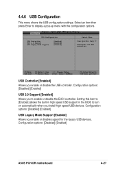
...: [Disabled] [Enabled] USB Legacy Mode Support [Enabled] Allows you install high speed USB devices. Configuration options: [Disabled] [Enabled] ASUS PCH-DR motherboard 4-27 Setting this item to [Enabled] allows the built-in high speed USB support in the BIOS to display a pop-up menu with the configuration options. Select an item then press Enter to turn on automatically when you enable or disable support for the legacy USB devices. USB Configuration USB Controller USB 2.0 Support USB Legacy Mode Support [Enabled] [Enabled] [Enabled] Select Menu Item Specific Help Configures...
...: [Disabled] [Enabled] USB Legacy Mode Support [Enabled] Allows you install high speed USB devices. Configuration options: [Disabled] [Enabled] ASUS PCH-DR motherboard 4-27 Setting this item to [Enabled] allows the built-in high speed USB support in the BIOS to display a pop-up menu with the configuration options. Select an item then press Enter to turn on automatically when you enable or disable support for the legacy USB devices. USB Configuration USB Controller USB 2.0 Support USB Legacy Mode Support [Enabled] [Enabled] [Enabled] Select Menu Item Specific Help Configures...

User Guide
Page 86
...Off] [Enabled] [Enabled] [Button Only] Enter Ctrl-F1 [Disabled] 0 0: 0: 0 Select Menu Item Specific Help This field allows you to change the power management settings. ACPI APIC Support APM Configuration Hardware Configuration [Enabled] Select Menu Item Specific Help Enable/Disable ACPI support for Operating System. ACPI APIC Support [Enabled] Allows you to set the automatic power saving features. 4-28 Chapter 4: BIOS Setup Select an item then press Enter to display the configuration options. APM Configuration Power Management HDD Power Down Suspend Mode Suspend Type Restore...
...Off] [Enabled] [Enabled] [Button Only] Enter Ctrl-F1 [Disabled] 0 0: 0: 0 Select Menu Item Specific Help This field allows you to change the power management settings. ACPI APIC Support APM Configuration Hardware Configuration [Enabled] Select Menu Item Specific Help Enable/Disable ACPI support for Operating System. ACPI APIC Support [Enabled] Allows you to set the automatic power saving features. 4-28 Chapter 4: BIOS Setup Select an item then press Enter to display the configuration options. APM Configuration Power Management HDD Power Down Suspend Mode Suspend Type Restore...

User Guide
Page 93
... you to [Enabled] clear the case open status feature. 4.6.4 Boot Settings Configuration Boot Settings Configuration Boot Other Device Quick Power On Self Test Halt On Case Open Warning Boot Up Floppy Seek Boot Up NumLock Status Typematic Rate Setting Typematic Rate (Chars/Sec) Typematic Delay (Msec) [Enabled] [Enabled] [All Errors] [Enabled] [Enabled] [On] [Disabled] 6 250 Select Menu Item Specific Help Select your Boot Device Priority. Configuration options: [Disabled] [Enabled] ASUS PCH-DR motherboard 4-35 Configuration options: [Disabled] [Enabled] Halt On [All Errors] Sets the...
... you to [Enabled] clear the case open status feature. 4.6.4 Boot Settings Configuration Boot Settings Configuration Boot Other Device Quick Power On Self Test Halt On Case Open Warning Boot Up Floppy Seek Boot Up NumLock Status Typematic Rate Setting Typematic Rate (Chars/Sec) Typematic Delay (Msec) [Enabled] [Enabled] [All Errors] [Enabled] [Enabled] [On] [Disabled] 6 250 Select Menu Item Specific Help Select your Boot Device Priority. Configuration options: [Disabled] [Enabled] ASUS PCH-DR motherboard 4-35 Configuration options: [Disabled] [Enabled] Halt On [All Errors] Sets the...


