User Manual
Page 3
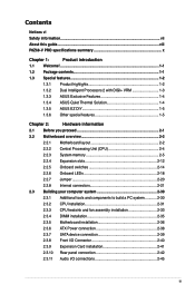
...About this guide...viii P8Z68-V PRO specifications summary x Chapter 1: Product introduction 1.1 Welcome!...1-1 1.2 Package contents 1-1 1.3 Special features 1-2 1.3.1 Product highlights 1-2 1.3.2 Dual Intelligent Processors 2 with DIGI+ VRM 1-3 1.3.3 ASUS Exclusive Features 1-4 1.3.4 ASUS Quiet Thermal Solution 1-4 1.3.5 ASUS EZ DIY 1-5 ...fan assembly installation 2-33 2.3.4 DIMM installation 2-35 2.3.5 Motherboard installation 2-36 2.3.6 ATX Power connection 2-38 2.3.7 SATA device connection 2-39 2.3.8 Front I/O Connector 2-40 2.3.9 Expension Card installation 2-...
...About this guide...viii P8Z68-V PRO specifications summary x Chapter 1: Product introduction 1.1 Welcome!...1-1 1.2 Package contents 1-1 1.3 Special features 1-2 1.3.1 Product highlights 1-2 1.3.2 Dual Intelligent Processors 2 with DIGI+ VRM 1-3 1.3.3 ASUS Exclusive Features 1-4 1.3.4 ASUS Quiet Thermal Solution 1-4 1.3.5 ASUS EZ DIY 1-5 ...fan assembly installation 2-33 2.3.4 DIMM installation 2-35 2.3.5 Motherboard installation 2-36 2.3.6 ATX Power connection 2-38 2.3.7 SATA device connection 2-39 2.3.8 Front I/O Connector 2-40 2.3.9 Expension Card installation 2-...

User Manual
Page 7
...fix it , carefully read all the manuals that all cables are correctly connected and the power cables are connected. Do not place the product in your area. If possible, disconnect all power cables from the existing system before you are using an adapter or extension cord. If ... devices are unplugged before the signal cables are not damaged. Safety information Electrical safety • To prevent electrical shock hazard, disconnect the power cable from the electrical outlet before relocating the system. • When adding or removing devices to the correct voltage in any damage, ...
...fix it , carefully read all the manuals that all cables are correctly connected and the power cables are connected. Do not place the product in your area. If possible, disconnect all power cables from the existing system before you are using an adapter or extension cord. If ... devices are unplugged before the signal cables are not damaged. Safety information Electrical safety • To prevent electrical shock hazard, disconnect the power cable from the electrical outlet before relocating the system. • When adding or removing devices to the correct voltage in any damage, ...

User Manual
Page 11
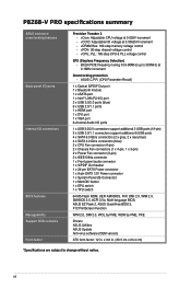
... 3.0 ports at mid-board for iGPU ASUS EPU - ASUS CrashFree BIOS 3 - ASUS Q-Connector - Supports Jack-Detection, Multi-Streaming and Front Panel Jack-Retasking - ASUS UEFI BIOS EZ Mode featuring friendly graphics user interface - Industry leading Digital 16-phase* Power Design - Utility Realtek® ALC892 8-channel High Definition Audio CODEC - P8Z68-V PRO specifications summary Bluetooth Audio IEEE 1394...
... 3.0 ports at mid-board for iGPU ASUS EPU - ASUS CrashFree BIOS 3 - ASUS Q-Connector - Supports Jack-Detection, Multi-Streaming and Front Panel Jack-Retasking - ASUS UEFI BIOS EZ Mode featuring friendly graphics user interface - Industry leading Digital 16-phase* Power Design - Utility Realtek® ALC892 8-channel High Definition Audio CODEC - P8Z68-V PRO specifications summary Bluetooth Audio IEEE 1394...
User Manual
Page 12
...Fan connector (4-pin) 2 x Chassis Fan connectors (1 x 4-pin, 1 x 3-pin) 2 x Power Fan connector (3-pin) 2 x IEEE1394a connector 1 x Front panel audio connector 1 x S/PDIF Out header 1 x 24-pin EATX Power connector 1 x 8-pin EATX 12V Power connector 1 x System Panel (Q-Connector) 1 x MemOK! vCPU_PLL: 160-step CPU & PLL voltage ...increment - BCLK/PCIE frequency tuning from 80MHz up to change without notice. P8Z68-V PRO specifications summary ASUS exclusive overclocking features Back panel I/O ports Internal I/O connectors BIOS features Manageability Support DVD contents Form factor Precision ...
...Fan connector (4-pin) 2 x Chassis Fan connectors (1 x 4-pin, 1 x 3-pin) 2 x Power Fan connector (3-pin) 2 x IEEE1394a connector 1 x Front panel audio connector 1 x S/PDIF Out header 1 x 24-pin EATX Power connector 1 x 8-pin EATX 12V Power connector 1 x System Panel (Q-Connector) 1 x MemOK! vCPU_PLL: 160-step CPU & PLL voltage ...increment - BCLK/PCIE frequency tuning from 80MHz up to change without notice. P8Z68-V PRO specifications summary ASUS exclusive overclocking features Back panel I/O ports Internal I/O connectors BIOS features Manageability Support DVD contents Form factor Precision ...

User Manual
Page 14
...174; Smart Response Technology boosts overall system performance. Quad-GPU SLI™ and Quad-GPU CrossFireX™ Support The motherboard's powerful Intel® Z68 platform optimizes PCIe allocation in multiple-GPU configurations of current bus systems. Moreover, Intel® Z68 Express Chipset ...65533;�C�o�r�e i5��/�C��o�r�e i3�� processors are among the most powerful and energy efficient CPUs in the world. It uses serial point-to launch Intel® Smart Response Technology. The dual-...
...174; Smart Response Technology boosts overall system performance. Quad-GPU SLI™ and Quad-GPU CrossFireX™ Support The motherboard's powerful Intel® Z68 platform optimizes PCIe allocation in multiple-GPU configurations of current bus systems. Moreover, Intel® Z68 Express Chipset ...65533;�C�o�r�e i5��/�C��o�r�e i3�� processors are among the most powerful and energy efficient CPUs in the world. It uses serial point-to launch Intel® Smart Response Technology. The dual-...
User Manual
Page 15
... DIGI+ VRM digital power design empowers users with superior flexibility and perfect precision to a digital standard. ASUS provides extra SATA 6.0 Gb/s ports with enhanced scalability, faster data retrieval, and double the bandwidth of two onboard chips-EPU (Energy Processing Unit) and TPU (TurboV Processing Unit). ASUS P8Z68-V PRO 1-3 With iGPU on P8Z68-V PRO motherboards, DIGI+ VRM intelligently...
... DIGI+ VRM digital power design empowers users with superior flexibility and perfect precision to a digital standard. ASUS provides extra SATA 6.0 Gb/s ports with enhanced scalability, faster data retrieval, and double the bandwidth of two onboard chips-EPU (Energy Processing Unit) and TPU (TurboV Processing Unit). ASUS P8Z68-V PRO 1-3 With iGPU on P8Z68-V PRO motherboards, DIGI+ VRM intelligently...

User Manual
Page 16
This also reduces fan noise and extends component longevity! 1.3.3 ASUS Exclusive Features GPU Boost GPU Boost accelerates the integrated CPU for motherboard users, but also the heatsink design lowers the temperature of the chipset and power phase area through a simple onboard switch or AI Suite... II utility. It easily delivers stable systemlevel upgrades for every use functions, with 7 special functions that offers users a noiseless PC environment. ASUS BT GO! quickly ensures memory boot...
This also reduces fan noise and extends component longevity! 1.3.3 ASUS Exclusive Features GPU Boost GPU Boost accelerates the integrated CPU for motherboard users, but also the heatsink design lowers the temperature of the chipset and power phase area through a simple onboard switch or AI Suite... II utility. It easily delivers stable systemlevel upgrades for every use functions, with 7 special functions that offers users a noiseless PC environment. ASUS BT GO! quickly ensures memory boot...

User Manual
Page 17
... more flexible and convenient mouse input. ASUS Q-Design ASUS Q-Design enhances your motherboard against static electricity and shields it ideally protects your DIY experience. ASUS Q-Connector ASUS Q-Connector allows you to update the BIOS without the usual "fingers" - ASUS P8Z68-V PRO 1-5 Quick and simple overclocking and setup...than 2.2TB in idle mode to lower utilization, heat, fan speed and power draw down to near zero, making it convenient and easy to the best available graphics resources based on power, performance and system load on Windows® 7 based PCs. With better...
... more flexible and convenient mouse input. ASUS Q-Design ASUS Q-Design enhances your motherboard against static electricity and shields it ideally protects your DIY experience. ASUS Q-Connector ASUS Q-Connector allows you to update the BIOS without the usual "fingers" - ASUS P8Z68-V PRO 1-5 Quick and simple overclocking and setup...than 2.2TB in idle mode to lower utilization, heat, fan speed and power draw down to near zero, making it convenient and easy to the best available graphics resources based on power, performance and system load on Windows® 7 based PCs. With better...
User Manual
Page 19
ASUS P8Z68-V PRO 2-1 Failure to do so may cause severe damage to avoid touching the ... Take note of the following precautions before you install or remove any component, ensure that the ATX power supply is switched off or the power cord is detached from the wall socket before touching any component. • Before handling components, use... a grounded wrist strap or touch a safely grounded object or a metal object, such as the power supply case, to avoid damaging them . • Whenever you uninstall any component, place it on a grounded antistatic pad or...
ASUS P8Z68-V PRO 2-1 Failure to do so may cause severe damage to avoid touching the ... Take note of the following precautions before you install or remove any component, ensure that the ATX power supply is switched off or the power cord is detached from the wall socket before touching any component. • Before handling components, use... a grounded wrist strap or touch a safely grounded object or a metal object, such as the power supply case, to avoid damaging them . • Whenever you uninstall any component, place it on a grounded antistatic pad or...

User Manual
Page 22
...any damage to the socket contacts resulting from incorrect CPU installation/removal, or misplacement/loss/incorrect removal of the motherboard, ensure that all power cables are unplugged before installing the CPU. • The LGA1156 CPU is on the LGA1155 socket. • The product warranty ...does not cover damage to the PnP cap/socket contacts/motherboard components. ASUS will process Return Merchandise Authorization (RMA) requests only if the motherboard comes with a surface mount LGA1155 socket designed for the Intel®...
...any damage to the socket contacts resulting from incorrect CPU installation/removal, or misplacement/loss/incorrect removal of the motherboard, ensure that all power cables are unplugged before installing the CPU. • The LGA1156 CPU is on the LGA1155 socket. • The product warranty ...does not cover damage to the PnP cap/socket contacts/motherboard components. ASUS will process Return Merchandise Authorization (RMA) requests only if the motherboard comes with a surface mount LGA1155 socket designed for the Intel®...
User Manual
Page 26
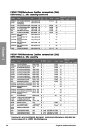
...(XMP) 12GB ( 3x 4GB ) DS Patriot PVT36G2000LLK(XMP) 6GB(3 x 2GB) DS Silicon SP002GBLYU200S02(XMP) 2GB DS Power Team TXD32048M2000C9(XMP) 2GB DS Team TXD32048M2000C9-L(XMP) 2GB DS Team TXD32048M2000C9-L(XMP) 2GB DS - - - KINGSTON KHX2133C9D3T1K2/... 9 1.65 • • 9 1.65 • • 9 1.65 • • 9-11-9-27 1.66 • • Chapter 2 P8Z68-V PRO Motherboard Qualified Vendors Lists (QVL) DDR3-1866 (O.C.) MHz capability Vendors Part No. T3D1288RT-20 9-9-9-24 1.5 T3D1288LT-20 9-9-9-24 1.5 T3D1288RT-20 9-9-9-24 1.6 DIMM socket...
...(XMP) 12GB ( 3x 4GB ) DS Patriot PVT36G2000LLK(XMP) 6GB(3 x 2GB) DS Silicon SP002GBLYU200S02(XMP) 2GB DS Power Team TXD32048M2000C9(XMP) 2GB DS Team TXD32048M2000C9-L(XMP) 2GB DS Team TXD32048M2000C9-L(XMP) 2GB DS - - - KINGSTON KHX2133C9D3T1K2/... 9 1.65 • • 9 1.65 • • 9 1.65 • • 9-11-9-27 1.66 • • Chapter 2 P8Z68-V PRO Motherboard Qualified Vendors Lists (QVL) DDR3-1866 (O.C.) MHz capability Vendors Part No. T3D1288RT-20 9-9-9-24 1.5 T3D1288LT-20 9-9-9-24 1.5 T3D1288RT-20 9-9-9-24 1.6 DIMM socket...
User Manual
Page 28
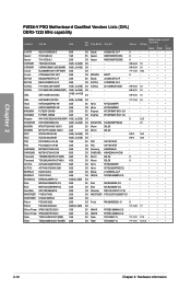
... Patriot PGS34G1333LLKA 4GB(2 x 2GB) DS Silicon Power SP001GBLTE133S01 1GB SS Silicon Power SP002GBLTE133S01 2GB DS Team TXD31024M1333C7(XMP) 1GB SS Team TXD32048M1333C7-D(XMP) 2GB DS Elpida Apacer Apacer MICRON Elpida ELPIDA G.SKILL - Size SS/ DS Chip Brand Chip NO. Elixir N2CB2G808N-CG - KINGTIGER KTG1333PS1208NST-C9 - - - - Chapter 2 P8Z68-V PRO Motherboard Qualified Vendors Lists (QVL) DDR3...
... Patriot PGS34G1333LLKA 4GB(2 x 2GB) DS Silicon Power SP001GBLTE133S01 1GB SS Silicon Power SP002GBLTE133S01 2GB DS Team TXD31024M1333C7(XMP) 1GB SS Team TXD32048M1333C7-D(XMP) 2GB DS Elpida Apacer Apacer MICRON Elpida ELPIDA G.SKILL - Size SS/ DS Chip Brand Chip NO. Elixir N2CB2G808N-CG - KINGTIGER KTG1333PS1208NST-C9 - - - - Chapter 2 P8Z68-V PRO Motherboard Qualified Vendors Lists (QVL) DDR3...

User Manual
Page 30
... Express operating mode PCIe 2.0 x16_1 x16 (Recommend for single VGA) x8 PCIe 2.0 x16_2 N/A x8 2-12 Chapter 2: Hardware information Chapter 2 Slot No. Failure to unplug the power cord before adding or removing expansion cards. 2.2.4 Expansion slots Ensure to do so may cause you physical injury and damage motherboard components.
... Express operating mode PCIe 2.0 x16_1 x16 (Recommend for single VGA) x8 PCIe 2.0 x16_2 N/A x8 2-12 Chapter 2: Hardware information Chapter 2 Slot No. Failure to unplug the power cord before adding or removing expansion cards. 2.2.4 Expansion slots Ensure to do so may cause you physical injury and damage motherboard components.

User Manual
Page 31
... Mode X4 (Recommend for high speed N/A device) X1 Mode X1 X1 * Please refer to get better performance. • We recommend that you provide sufficient power when running CrossFireX™ or SLI™ mode. PCIEx1_1 - - PCI_1 - - shared - - - - Marvell® SATA 6G Controller - - - See page 2-23 for details. PCIEx16_2 shared - - - - - - - PCIEx1_2/USB3_1234 - ASUS P8Z68-V PRO 2-13
... Mode X4 (Recommend for high speed N/A device) X1 Mode X1 X1 * Please refer to get better performance. • We recommend that you provide sufficient power when running CrossFireX™ or SLI™ mode. PCIEx1_1 - - PCI_1 - - shared - - - - Marvell® SATA 6G Controller - - - See page 2-23 for details. PCIEx16_2 shared - - - - - - - PCIEx1_2/USB3_1234 - ASUS P8Z68-V PRO 2-13

User Manual
Page 32
...system. Chapter 2 2-14 Chapter 2: Hardware information The illustration below shows the location of the onboard power-on switch that you should shut down the system and unplug the power cable before removing or plugging in any motherboard component. 2.2.5 Onboard switches Onboard switches allow you to... reboot the system. The switch also lights up the system. This is plugged to a power source indicating that allows you to power up or wake up when the system is ideal for overclockers and gamers who continually change settings to enhance system performance...
...system. Chapter 2 2-14 Chapter 2: Hardware information The illustration below shows the location of the onboard power-on switch that you should shut down the system and unplug the power cable before removing or plugging in any motherboard component. 2.2.5 Onboard switches Onboard switches allow you to... reboot the system. The switch also lights up the system. This is plugged to a power source indicating that allows you to power up or wake up when the system is ideal for overclockers and gamers who continually change settings to enhance system performance...
User Manual
Page 33
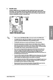
...messgae will appear during the tuning process, the system continues memory tuning after turning on the ASUS website at www.asus.com after the whole tuning process, the DRAM_LED lights continuously. switch to test one set...loads and tests failsafe memory settings. function. • The MemOK! The blinking speed of failsafe settings. ASUS P8Z68-V PRO 2-15 switch Installing DIMMs that you turn off the computer and replace DIMMs during POST reminding you that ... tuning, turn off the computer and unplug the power cord for the system to boot and load BIOS default settings. MemOK!
...messgae will appear during the tuning process, the system continues memory tuning after turning on the ASUS website at www.asus.com after the whole tuning process, the DRAM_LED lights continuously. switch to test one set...loads and tests failsafe memory settings. function. • The MemOK! The blinking speed of failsafe settings. ASUS P8Z68-V PRO 2-15 switch Installing DIMMs that you turn off the computer and replace DIMMs during POST reminding you that ... tuning, turn off the computer and unplug the power cord for the system to boot and load BIOS default settings. MemOK!

User Manual
Page 34
For ensuring the system performance, turn the switch setting to Enable when the system is powered off. • The TPU LED (O2LED1) near the TPU switch lights when the switch setting is turned to Enable under the OS environment, the TPU ...
For ensuring the system performance, turn the switch setting to Enable when the system is powered off. • The TPU LED (O2LED1) near the TPU switch lights when the switch setting is turned to Enable under the OS environment, the TPU ...

User Manual
Page 35
Refer to section 2.2.6 Onboard LEDs for the exact location of the EPU LED. • If you have made. ASUS P8Z68-V PRO 2-17 For ensuring the system performance, turn the switch setting to Enable when the system is powered off. • The EPU LED (O2LED2) near the EPU switch lights when the switch setting is turned... setup program, and enable the EPU function at the same time. However, the system will automatically detect the current PC loadings and intelligently moderate the power consumption.
Refer to section 2.2.6 Onboard LEDs for the exact location of the EPU LED. • If you have made. ASUS P8Z68-V PRO 2-17 For ensuring the system performance, turn the switch setting to Enable when the system is powered off. • The EPU LED (O2LED2) near the EPU switch lights when the switch setting is turned... setup program, and enable the EPU function at the same time. However, the system will automatically detect the current PC loadings and intelligently moderate the power consumption.

User Manual
Page 36
2.2.6 Onboard LEDs 1. This user-friendly design provides an intuitional way to the error device will continue lighting until the problem is found , the LED next to locate the root problem within a second. POST State LEDs The POST State LEDs of CPU, DRAM, VGA card, and HDD indicate key components status during POST (Power-on Self Test). Chapter 2 2-18 Chapter 2: Hardware information If an error is solved.
2.2.6 Onboard LEDs 1. This user-friendly design provides an intuitional way to the error device will continue lighting until the problem is found , the LED next to locate the root problem within a second. POST State LEDs The POST State LEDs of CPU, DRAM, VGA card, and HDD indicate key components status during POST (Power-on Self Test). Chapter 2 2-18 Chapter 2: Hardware information If an error is solved.
User Manual
Page 38
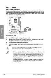
... and turn off is required to clear the CMOS RTC RAM data. function. Turn OFF the computer and unplug the power cord. 2. After the CMOS clearance, reinstall the battery. • You do not help, remove the onboard battery and move the cap back to pins 2-3.... CMOS RTC RAM data. You can automatically reset parameter settings to default values. • Due to the chipset behavior, AC power off and on the power supply or unplug and plug the power cord before rebooting the system. 2-20 Chapter 2: Hardware information Removing the cap will cause system boot failure! • If...
... and turn off is required to clear the CMOS RTC RAM data. function. Turn OFF the computer and unplug the power cord. 2. After the CMOS clearance, reinstall the battery. • You do not help, remove the onboard battery and move the cap back to pins 2-3.... CMOS RTC RAM data. You can automatically reset parameter settings to default values. • Due to the chipset behavior, AC power off and on the power supply or unplug and plug the power cord before rebooting the system. 2-20 Chapter 2: Hardware information Removing the cap will cause system boot failure! • If...


