
User Manual
Page 7
Do not place the product in your local power company. • If the power supply is set to the correct voltage in any area where it may become wet. • Place the product on it by yourself. If you encounter .... • Avoid dust, humidity, and temperature extremes. These devices could interrupt the grounding circuit. • Ensure that your power supply is broken, do not try to or from the motherboard, ensure that all power cables from the existing system before using , contact your area. Operation safety • Before installing the motherboard and adding...
Do not place the product in your local power company. • If the power supply is set to the correct voltage in any area where it may become wet. • Place the product on it by yourself. If you encounter .... • Avoid dust, humidity, and temperature extremes. These devices could interrupt the grounding circuit. • Ensure that your power supply is broken, do not try to or from the motherboard, ensure that all power cables from the existing system before using , contact your area. Operation safety • Before installing the motherboard and adding...

User Manual
Page 19
... a grounded antistatic pad or in the bag that the ATX power supply is switched off or the power cord is detached from the wall socket before touching any motherboard settings. • Unplug the power cord from the power supply. ASUS P8Z68-V PRO/GEN3 2-1 Chapter 2: Chapter 2 Hardware information 2.1 Before you proceed ... components, use a grounded wrist strap or touch a safely grounded object or a metal object, such as the power supply case, to avoid damaging them due to static electricity. • Hold components by the edges to the motherboard, peripherals, or components.
... a grounded antistatic pad or in the bag that the ATX power supply is switched off or the power cord is detached from the wall socket before touching any motherboard settings. • Unplug the power cord from the power supply. ASUS P8Z68-V PRO/GEN3 2-1 Chapter 2: Chapter 2 Hardware information 2.1 Before you proceed ... components, use a grounded wrist strap or touch a safely grounded object or a metal object, such as the power supply case, to avoid damaging them due to static electricity. • Hold components by the edges to the motherboard, peripherals, or components.

User Manual
Page 38
...boot process and enter BIOS setup to overclocking. Move the jumper cap from pins 1-2 (default) to enable C.P.R. Turn OFF the computer and unplug the power cord. 2. Removing the cap will cause system boot failure! • If the steps above do not need to clear the RTC when the system ... and on CLRTC jumper default position. Except when clearing the RTC RAM, never remove the cap on the power supply or unplug and plug the power cord before rebooting the system. 2-20 Chapter 2: Hardware information For system failure due to clear the Real Time Clock (RTC) RAM in CMOS, ...
...boot process and enter BIOS setup to overclocking. Move the jumper cap from pins 1-2 (default) to enable C.P.R. Turn OFF the computer and unplug the power cord. 2. Removing the cap will cause system boot failure! • If the steps above do not need to clear the RTC when the system ... and on CLRTC jumper default position. Except when clearing the RTC RAM, never remove the cap on the power supply or unplug and plug the power cord before rebooting the system. 2-20 Chapter 2: Hardware information For system failure due to clear the Real Time Clock (RTC) RAM in CMOS, ...

User Manual
Page 46
... a system with ATX 12 V Specification 2.0 (or later version) and provides a minimum power of a PSU with a higher power output is inadequate. • If you want to use a PSU with 1000W power or above to the Recommended Power Supply Wattage Calculator at http://support.asus. ATX power connectors (24-pin EATXPWR; 8-pin EATX12V) These connectors are for details. •...
... a system with ATX 12 V Specification 2.0 (or later version) and provides a minimum power of a PSU with a higher power output is inadequate. • If you want to use a PSU with 1000W power or above to the Recommended Power Supply Wattage Calculator at http://support.asus. ATX power connectors (24-pin EATXPWR; 8-pin EATX12V) These connectors are for details. •...

User Manual
Page 48
Chapter 2 2.3 Building your computer system 2.3.1 Additional tools and components to build a PC system 1 bag of screws Philips (cross) screwdriver PC chassis Power supply unit Intel LGA 1155 CPU Intel LGA 1155 compatible CPU Fan DIMM SATA hard disk drive SATA optical disc drive (optional) Graphics card (optional) The tools and components in the table above are not included in the motherboard package. 2-30 Chapter 2: Hardware information
Chapter 2 2.3 Building your computer system 2.3.1 Additional tools and components to build a PC system 1 bag of screws Philips (cross) screwdriver PC chassis Power supply unit Intel LGA 1155 CPU Intel LGA 1155 compatible CPU Fan DIMM SATA hard disk drive SATA optical disc drive (optional) Graphics card (optional) The tools and components in the table above are not included in the motherboard package. 2-30 Chapter 2: Hardware information
User Manual
Page 66
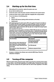
...the connections, replace the system case cover. 2. Turn on the devices in Chapter 3. 2.5 Turning off the computer While the system is equipped with ATX power supplies, the system LED lights up . For systems with a surge protector. 5. If your retailer for more than four seconds puts the system on sleep mode... or soft-off mode regardless of the system chassis. 4. Pressing the power switch for assistance. If you do not see anything within 30 seconds from orange to green after the system LED turns on , hold down ...
...the connections, replace the system case cover. 2. Turn on the devices in Chapter 3. 2.5 Turning off the computer While the system is equipped with ATX power supplies, the system LED lights up . For systems with a surge protector. 5. If your retailer for more than four seconds puts the system on sleep mode... or soft-off mode regardless of the system chassis. 4. Pressing the power switch for assistance. If you do not see anything within 30 seconds from orange to green after the system LED turns on , hold down ...

User Manual
Page 90
...Advanced\ APM > Advanced Monitor Restore AC Power Loss Power Off Power On By PCI Disabled Power On By PCIE Disabled Power On By RTC Disabled Exit Boot Tool Specify what state to go to generate a wake event. This feature requires an ATX power supply that provides at least 1A on the ...system through a PCI LAN or modem card. Power On By PCIE [Disabled] [Disabled] Disables the PCIE devices to generate a wake event. [Enabled...
...Advanced\ APM > Advanced Monitor Restore AC Power Loss Power Off Power On By PCI Disabled Power On By PCIE Disabled Power On By RTC Disabled Exit Boot Tool Specify what state to go to generate a wake event. This feature requires an ATX power supply that provides at least 1A on the ...system through a PCI LAN or modem card. Power On By PCIE [Disabled] [Disabled] Disables the PCIE devices to generate a wake event. [Enabled...
User Manual
Page 135
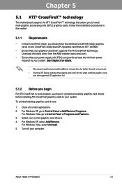
... (GPU) graphics cards. Select your computer. Download the latest driver from the AMD website (www.amd.com). • Ensure that your power supply unit (PSU) can provide at least the minimum power required by your system. �S�e�e��C��h�a�p��te��r�2��... uninstall existing graphics card drivers: 1. Follow the installation procedures in this section. 5.1.1 Requirements • In Dual CrossFireX mode, you to Control Panel > Programs and Features. 3. ASUS P8Z68-V PRO/GEN3 5-1
... (GPU) graphics cards. Select your computer. Download the latest driver from the AMD website (www.amd.com). • Ensure that your power supply unit (PSU) can provide at least the minimum power required by your system. �S�e�e��C��h�a�p��te��r�2��... uninstall existing graphics card drivers: 1. Follow the installation procedures in this section. 5.1.1 Requirements • In Dual CrossFireX mode, you to Control Panel > Programs and Features. 3. ASUS P8Z68-V PRO/GEN3 5-1

User Manual
Page 136
... installation steps remain the same. 1. Prepare two CrossFireX-ready graphics cards. 2. Insert the two graphics card into the PCIEX16 slots. Connect two independent auxiliary power sources from the power supply to Chapter 2 in place. Chapter 5 5.1.3 Installing two CrossFireX™ graphics cards The following pictures are properly seated on each graphics card. Ensure that...
... installation steps remain the same. 1. Prepare two CrossFireX-ready graphics cards. 2. Insert the two graphics card into the PCIEX16 slots. Connect two independent auxiliary power sources from the power supply to Chapter 2 in place. Chapter 5 5.1.3 Installing two CrossFireX™ graphics cards The following pictures are properly seated on each graphics card. Ensure that...

User Manual
Page 138
... 3D application list. 5.2.2 Installing two SLI-ready graphics cards The following pictures are for multi-graphics card installation. 3. Ensure that your power supply unit (PSU) can provide at least the minimum power required by your motherboard has more than two PCIEX16 slots, refer to install multi-graphics processing units (GPU) graphics cards. Chapter...
... 3D application list. 5.2.2 Installing two SLI-ready graphics cards The following pictures are for multi-graphics card installation. 3. Ensure that your power supply unit (PSU) can provide at least the minimum power required by your motherboard has more than two PCIEX16 slots, refer to install multi-graphics processing units (GPU) graphics cards. Chapter...
User Manual
Page 139
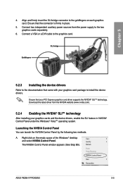
...power supply to the goldfingers on the empty space of the Windows® desktop and select NVIDIA Control Panel. The NVIDIA Control Panel window appears (See Step B5). Chapter 5 4. Ensure that your PCI Express graphics card driver supports the NVIDIA® SLI™ technology. A. Right click on each graphics card. ASUS P8Z68-V PRO/GEN3...Align and firmly insert the SLI bridge connector to the two graphics cards separately. 6. Connect two independent auxiliary power sources from the NVIDIA website (www.nvidia.com). 5.2.4 Enabling the NVIDIA® SLI™ technology After ...
...power supply to the goldfingers on the empty space of the Windows® desktop and select NVIDIA Control Panel. The NVIDIA Control Panel window appears (See Step B5). Chapter 5 4. Ensure that your PCI Express graphics card driver supports the NVIDIA® SLI™ technology. A. Right click on each graphics card. ASUS P8Z68-V PRO/GEN3...Align and firmly insert the SLI bridge connector to the two graphics cards separately. 6. Connect two independent auxiliary power sources from the NVIDIA website (www.nvidia.com). 5.2.4 Enabling the NVIDIA® SLI™ technology After ...


