User Manual
Page 23
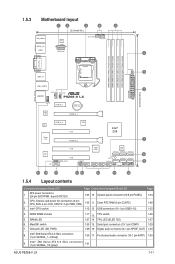
...14 TPU LED (ELED 730) 1-37 6. Onboard LED (SB_PWR) 1-36 16. Intel® Z68 Serial ATA 6.0 Gb/s connectors (7-pin SATA6G_1/2 [gray]) 1-31 ASUS P8Z68-V LX 1-11 Serial port connectors (10-1 pin COM1) 1-29 7. CPU, Chassis and power fan connectors (4-pin CPU_FAN, 4-pin CHA_FAN1/2, 3-pin PWR_FAN) 1-32 11. Intel&#... 13 12 11 10 1.5.4 Layout contents Connectors/Jumpers/Slots/LED Page Connectors/Jumpers/Slots/LED Page 1. Clear RTC RAM (3-pin CLRTC) 1-26 3. Digital audio connector (4-1 pin SPDIF_OUT) 1-30 8. Front panel audio connector (10-1 pin AAFP) 1-29 9.
...14 TPU LED (ELED 730) 1-37 6. Onboard LED (SB_PWR) 1-36 16. Intel® Z68 Serial ATA 6.0 Gb/s connectors (7-pin SATA6G_1/2 [gray]) 1-31 ASUS P8Z68-V LX 1-11 Serial port connectors (10-1 pin COM1) 1-29 7. CPU, Chassis and power fan connectors (4-pin CPU_FAN, 4-pin CHA_FAN1/2, 3-pin PWR_FAN) 1-32 11. Intel&#... 13 12 11 10 1.5.4 Layout contents Connectors/Jumpers/Slots/LED Page Connectors/Jumpers/Slots/LED Page 1. Clear RTC RAM (3-pin CLRTC) 1-26 3. Digital audio connector (4-1 pin SPDIF_OUT) 1-30 8. Front panel audio connector (10-1 pin AAFP) 1-29 9.
User Manual
Page 38
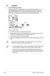
P8Z68-V LX CLRTC 12 23 Normal (Default) P8Z68-V LX Clear RTC RAM Clear RTC To erase the RTC RAM: 1. After clearing the CMOS, reinstall the battery. • You do not help, remove the onboard battery and move the cap back to clear the Real Time Clock (RTC) RAM in CMOS, which include system ...(C.P.R.) feature. Hold down and reboot the system, then the BIOS automatically resets parameter settings to re-enter data. Except when clearing the RTC RAM, never remove the cap on pins 2-3 for about 5-10 seconds, then move the jumper again to overclocking. You can clear the CMOS ...
P8Z68-V LX CLRTC 12 23 Normal (Default) P8Z68-V LX Clear RTC RAM Clear RTC To erase the RTC RAM: 1. After clearing the CMOS, reinstall the battery. • You do not help, remove the onboard battery and move the cap back to clear the Real Time Clock (RTC) RAM in CMOS, which include system ...(C.P.R.) feature. Hold down and reboot the system, then the BIOS automatically resets parameter settings to re-enter data. Except when clearing the RTC RAM, never remove the cap on pins 2-3 for about 5-10 seconds, then move the jumper again to overclocking. You can clear the CMOS ...
User Manual
Page 57
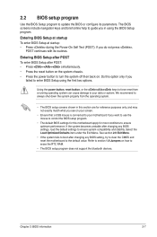
... operating system. • The BIOS setup screens shown in using the first two options. Do this section are for most conditions to erase the RTC RAM. • The BIOS setup program does not support the bluetooth devices. If you in this option only if you see on how to ensure optimum...
... operating system. • The BIOS setup screens shown in using the first two options. Do this section are for most conditions to erase the RTC RAM. • The BIOS setup program does not support the bluetooth devices. If you in this option only if you see on how to ensure optimum...
User Manual
Page 61
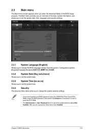
...default Not Installed. 2.3 Main menu The Main menu screen appears when you have forgotten your BIOS password, erase the CMOS Real Time Clock (RTC) RAM to clear the BIOS password. Configuration options: [English] 2.3.2 System Date [Day xx/xx/xxxx] Allows you to set the system date. 2.3.3 System...Language [English] Allows you to choose the BIOS language version from the options. See section 1.9 Jumpers for information on how to erase the RTC RAM. • The Administrator or User Password items on top of the basic system information, and allows you to set the system time. 2.3.4 ...
...default Not Installed. 2.3 Main menu The Main menu screen appears when you have forgotten your BIOS password, erase the CMOS Real Time Clock (RTC) RAM to clear the BIOS password. Configuration options: [English] 2.3.2 System Date [Day xx/xx/xxxx] Allows you to set the system date. 2.3.3 System...Language [English] Allows you to choose the BIOS language version from the options. See section 1.9 Jumpers for information on how to erase the RTC RAM. • The Administrator or User Password items on top of the basic system information, and allows you to set the system time. 2.3.4 ...


