
P8H77-I User's Manual
Page 3
... information vi About this guide vii P8H77-I specifications summary ix Chapter 1 Product introduction 1.1 Welcome 1-1 1.2 Package contents 1-1 1.3 Special features 1-1 1.3.1 Product highlights 1-1 1.3.2 Innovative ASUS features 1-3 1.4 Before you proceed 1-6 1.5 Motherboard overview 1-7 1.5.1 Placement direction 1-7 1.5.2 Screw holes 1-7 1.5.3 Motherboard layout 1-8 1.5.4 Layout contents 1-8 1.6 Central Processing Unit (CPU 1-9 1.6.1 Installing the CPU 1-9 1.6.2 Installing the CPU heatsink and fan 1-12 1.6.3 Uninstalling the CPU...
... information vi About this guide vii P8H77-I specifications summary ix Chapter 1 Product introduction 1.1 Welcome 1-1 1.2 Package contents 1-1 1.3 Special features 1-1 1.3.1 Product highlights 1-1 1.3.2 Innovative ASUS features 1-3 1.4 Before you proceed 1-6 1.5 Motherboard overview 1-7 1.5.1 Placement direction 1-7 1.5.2 Screw holes 1-7 1.5.3 Motherboard layout 1-8 1.5.4 Layout contents 1-8 1.6 Central Processing Unit (CPU 1-9 1.6.1 Installing the CPU 1-9 1.6.2 Installing the CPU heatsink and fan 1-12 1.6.3 Uninstalling the CPU...
P8H77-I User's Manual
Page 21
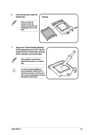
When you insert the load lever under the retention tab. Some heatsinks come with , ensuring that it is toxic and inedible. ASUS P8H77-I 1-11 If so, skip this step. Insert the load lever under the retention tab, the PnP cap disengages from the load plate. If it gets ... 7. The Thermal Interface Material is spread in an even thin layer. 6. Apply some Thermal Interface Material to the exposed area of the CPU that the heatsink will be in contact with preapplied thermal paste.
When you insert the load lever under the retention tab. Some heatsinks come with , ensuring that it is toxic and inedible. ASUS P8H77-I 1-11 If so, skip this step. Insert the load lever under the retention tab, the PnP cap disengages from the load plate. If it gets ... 7. The Thermal Interface Material is spread in an even thin layer. 6. Apply some Thermal Interface Material to the exposed area of the CPU that the heatsink will be in contact with preapplied thermal paste.

P8H77-I User's Manual
Page 22
... ensure that you have installed the motherboard to the chassis before you use only Intel®‑certified multi‑directional heatsink and fan. • Your Intel® LGA1155 heatsink and fan assembly comes in place. A B 1 1 B A The type of the installed CPU, ensuring that you...at a time in size and dimension. If you buy a boxed Intel® processor, the package includes the CPU fan and heatsink assembly. To install the CPU heatsink and fan: A 1. The illustration above is incompatible with the LGA775 and LGA1366 sockets in a diagonal sequence to the CPU fan...
... ensure that you have installed the motherboard to the chassis before you use only Intel®‑certified multi‑directional heatsink and fan. • Your Intel® LGA1155 heatsink and fan assembly comes in place. A B 1 1 B A The type of the installed CPU, ensuring that you...at a time in size and dimension. If you buy a boxed Intel® processor, the package includes the CPU fan and heatsink assembly. To install the CPU heatsink and fan: A 1. The illustration above is incompatible with the LGA775 and LGA1366 sockets in a diagonal sequence to the CPU fan...
P8H77-I User's Manual
Page 23
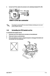
CPU_FAN CPU FAN PWM CPU FAN IN CPU FAN PWR GND P8H77-I P8H77-I 1-13 Pull up two fasteners at a time in a diagonal sequence to connect the CPU fan connector! Hardware monitoring errors can occur if you ...fan cable from the motherboard. Connect the CPU fan cable to plug this connector. 1.6.3 Uninstalling the CPU heatsink and fan To uninstall the CPU heatsink and fan: 1. 3. Rotate each fastener counterclockwise. 3. A B A B B A B A ASUS P8H77-I CPU fan connector Do not forget to disengage the heatsink and fan assembly from the connector on the motherboard labeled CPU_FAN.
CPU_FAN CPU FAN PWM CPU FAN IN CPU FAN PWR GND P8H77-I P8H77-I 1-13 Pull up two fasteners at a time in a diagonal sequence to connect the CPU fan connector! Hardware monitoring errors can occur if you ...fan cable from the motherboard. Connect the CPU fan cable to plug this connector. 1.6.3 Uninstalling the CPU heatsink and fan To uninstall the CPU heatsink and fan: 1. 3. Rotate each fastener counterclockwise. 3. A B A B B A B A ASUS P8H77-I CPU fan connector Do not forget to disengage the heatsink and fan assembly from the connector on the motherboard labeled CPU_FAN.

P8H77-I User's Manual
Page 24
4. Carefully remove the heatsink and fan assembly from the motherboard. 5. Rotate each fastener clockwise to prevent installation on a DDR2 DIMM socket. DDR3 modules are developed for better performance with ... 3 (DDR3) Dual Inline Memory Modules (DIMM) sockets. The figure illustrates the location of the DDR3 DIMM sockets: DIMM_A1 DIMM_B1 Channel Channel A Channel B Sockets DIMM_A1 DIMM_B1 P8H77-I P8H77-I 240-pin DDR3 DIMM sockets 1-14 Chapter 1: Product introduction A DDR3 module has the same physical dimensions as a DDR2 DIMM but is notched differently to ensure...
4. Carefully remove the heatsink and fan assembly from the motherboard. 5. Rotate each fastener clockwise to prevent installation on a DDR2 DIMM socket. DDR3 modules are developed for better performance with ... 3 (DDR3) Dual Inline Memory Modules (DIMM) sockets. The figure illustrates the location of the DDR3 DIMM sockets: DIMM_A1 DIMM_B1 Channel Channel A Channel B Sockets DIMM_A1 DIMM_B1 P8H77-I P8H77-I 240-pin DDR3 DIMM sockets 1-14 Chapter 1: Product introduction A DDR3 module has the same physical dimensions as a DDR2 DIMM but is notched differently to ensure...
