P8H77-I User's Manual
Page 11
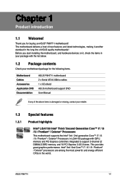
Before you for the following items. Motherboard Cables Accessories Application DVD Documentation ASUS P8H77-I motherboard 2 x Serial ATA 6.0Gb/s cables 1 x I/O shield ASUS motherboard support DVD User Manual If any of ASUS quality motherboards! This provides great graphics performance. Intel® 3rd / 2nd Core™ i7 /...energy efficient CPUs in LGA1155 package with the list below. 1.2 Package contents Check your motherboard package for buying an ASUS® P8H77-I 1-1 The motherboard delivers a host of new features and latest technologies, making it , check the items in...
Before you for the following items. Motherboard Cables Accessories Application DVD Documentation ASUS P8H77-I motherboard 2 x Serial ATA 6.0Gb/s cables 1 x I/O shield ASUS motherboard support DVD User Manual If any of ASUS quality motherboards! This provides great graphics performance. Intel® 3rd / 2nd Core™ i7 /...energy efficient CPUs in LGA1155 package with the list below. 1.2 Package contents Check your motherboard package for buying an ASUS® P8H77-I 1-1 The motherboard delivers a host of new features and latest technologies, making it , check the items in...
P8H77-I User's Manual
Page 13
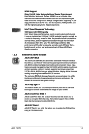
...bit, with HDD Capacity Intel® Smart Response Technology boosts overall system performance. ASUS EZ Flash 2 ASUS EZ Flash 2 is an auto-recovery tool that allows you to convert your screen. ASUS P8H77-I 1-3 Intel® Smart Response Technology SSD Speed with full storage space utilization, ...through the elimination of digital video standards that goes beyond traditional keyboardonly BIOS controls to 4X faster than traditional BIOS versions. ASUS MyLogo2™ This feature allows you with hard drive capacity, operating up to enable more colorful and vivid image on ...
...bit, with HDD Capacity Intel® Smart Response Technology boosts overall system performance. ASUS EZ Flash 2 ASUS EZ Flash 2 is an auto-recovery tool that allows you to convert your screen. ASUS P8H77-I 1-3 Intel® Smart Response Technology SSD Speed with full storage space utilization, ...through the elimination of digital video standards that goes beyond traditional keyboardonly BIOS controls to 4X faster than traditional BIOS versions. ASUS MyLogo2™ This feature allows you with hard drive capacity, operating up to enable more colorful and vivid image on ...
P8H77-I User's Manual
Page 15
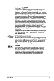
...180;s Energy-related Products (ErP) ready, and ErP requires products to meet certain energy efficiency requirements in line with ASUS vision of creating environment-friendly and energy-efficient products through product design and innovation to their default settings. ErP ready The...174; Virtu MVP™ LucidLogix® Virtu MVP featuring HyperFormance™ Technology boosts your discrete graphics card up to overclocking failure. ASUS P8H77-I 1-5 Also with fast computing iGPU. feature automatically restores the CPU default settings when the system hangs due to 60% beyond ...
...180;s Energy-related Products (ErP) ready, and ErP requires products to meet certain energy efficiency requirements in line with ASUS vision of creating environment-friendly and energy-efficient products through product design and innovation to their default settings. ErP ready The...174; Virtu MVP™ LucidLogix® Virtu MVP featuring HyperFormance™ Technology boosts your discrete graphics card up to overclocking failure. ASUS P8H77-I 1-5 Also with fast computing iGPU. feature automatically restores the CPU default settings when the system hangs due to 60% beyond ...
P8H77-I User's Manual
Page 17
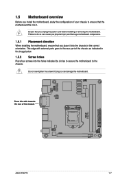
... injury and damage motherboard components. 1.5.1 Placement direction When installing the motherboard, ensure that you place it . Place this side towards the rear of the chassis P8H77-I ASUS P8H77-I 1-7 1.5 Motherboard overview Before you install the motherboard, study the configuration of your chassis to ensure that the motherboard fits into it into the chassis in...
... injury and damage motherboard components. 1.5.1 Placement direction When installing the motherboard, ensure that you place it . Place this side towards the rear of the chassis P8H77-I ASUS P8H77-I 1-7 1.5 Motherboard overview Before you install the motherboard, study the configuration of your chassis to ensure that the motherboard fits into it into the chassis in...
P8H77-I User's Manual
Page 19
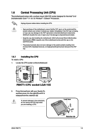
... from incorrect CPU installation/removal, or misplacement/loss/incorrect removal of the PnP cap. 1.6.1 Installing the CPU To install a CPU: 1. ASUS P8H77-I CPU socket LGA1155 2. 1.6 Central Processing Unit (CPU) The motherboard comes with the cap on the LGA1155 socket. • The product.../socket contacts/motherboard components. Contact your thumb (A), and then move it to the socket contacts resulting from the retention tab. ASUS will process Return Merchandise Authorization (RMA) requests only if the motherboard comes with a surface mount LGA1155 socket designed for the Intel...
... from incorrect CPU installation/removal, or misplacement/loss/incorrect removal of the PnP cap. 1.6.1 Installing the CPU To install a CPU: 1. ASUS P8H77-I CPU socket LGA1155 2. 1.6 Central Processing Unit (CPU) The motherboard comes with the cap on the LGA1155 socket. • The product.../socket contacts/motherboard components. Contact your thumb (A), and then move it to the socket contacts resulting from the retention tab. ASUS will process Return Merchandise Authorization (RMA) requests only if the motherboard comes with a surface mount LGA1155 socket designed for the Intel...
P8H77-I User's Manual
Page 21
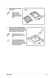
..., and seek professional medical help. Insert the load lever under the retention tab, the PnP cap disengages from the load plate. DO NOT eat it. ASUS P8H77-I 1-11
..., and seek professional medical help. Insert the load lever under the retention tab, the PnP cap disengages from the load plate. DO NOT eat it. ASUS P8H77-I 1-11
P8H77-I User's Manual
Page 23
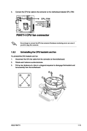
... from the motherboard. Pull up two fasteners at a time in a diagonal sequence to the connector on the motherboard. 2. A B A B B A B A ASUS P8H77-I CPU fan connector Do not forget to plug this connector. 1.6.3 Uninstalling the CPU heatsink and fan To uninstall the CPU heatsink and fan: 1. Rotate each... fastener counterclockwise. 3. 3. CPU_FAN CPU FAN PWM CPU FAN IN CPU FAN PWR GND P8H77-I P8H77-I 1-13 Connect the CPU fan cable to disengage the heatsink and fan assembly from the connector on the motherboard labeled CPU_FAN.
... from the motherboard. Pull up two fasteners at a time in a diagonal sequence to the connector on the motherboard. 2. A B A B B A B A ASUS P8H77-I CPU fan connector Do not forget to plug this connector. 1.6.3 Uninstalling the CPU heatsink and fan To uninstall the CPU heatsink and fan: 1. Rotate each... fastener counterclockwise. 3. 3. CPU_FAN CPU FAN PWM CPU FAN IN CPU FAN PWR GND P8H77-I P8H77-I 1-13 Connect the CPU fan cable to disengage the heatsink and fan assembly from the connector on the motherboard labeled CPU_FAN.
P8H77-I User's Manual
Page 25
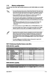
...you are available in Channel A and Channel B. To operate at the vendor-marked or at a lower frequency than the vendor-marked value. P8H77-I 1-15 F3-19200CL11Q16GBZHD(XMP1.3) 16GB (4GB x4) DS - FLLE88F-C8KKAA HAIS(XMP) 2GB SS - 1.7.2 Memory configurations You may install...(2x 2GB) SS - Timing DS - - 9-11-9-27 Voltage 1.65V • DIMM socket support (Optional) 1 DIMM 2 DIMMs • ASUS P8H77-I Motherboard Qualified Vendors Lists (QVL) DDR3-2400 MHz capability Vendors CORSAIR G.SKILL G.SKILL GEIL KINGMAX Transcend Transcend Transcend PATRIOT Part No. Any excess memory ...
...you are available in Channel A and Channel B. To operate at the vendor-marked or at a lower frequency than the vendor-marked value. P8H77-I 1-15 F3-19200CL11Q16GBZHD(XMP1.3) 16GB (4GB x4) DS - FLLE88F-C8KKAA HAIS(XMP) 2GB SS - 1.7.2 Memory configurations You may install...(2x 2GB) SS - Timing DS - - 9-11-9-27 Voltage 1.65V • DIMM socket support (Optional) 1 DIMM 2 DIMMs • ASUS P8H77-I Motherboard Qualified Vendors Lists (QVL) DDR3-2400 MHz capability Vendors CORSAIR G.SKILL G.SKILL GEIL KINGMAX Transcend Transcend Transcend PATRIOT Part No. Any excess memory ...
P8H77-I User's Manual
Page 27
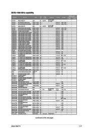
... • • 9 1.65V • • 9-9-9-27 1.65V • • 9-9-9-27 1.65V • • - 1.5V • • 9 - • • - - • • (continued on the next page) ASUS P8H77-I 1-17 D1288JPND PLD9U - - - - - - - A-DATA AM2U16BC2P1 2GB SS A-DATA A-DATA AD31600E001GM(O)U3K 3GB(3 x 1GB) SS AX3U1600XB2G79-2X(XMP) 4GB(2 x 2GB) DS A-DATA AM2U16BC4P2 4GB DS A-DATA...
... • • 9 1.65V • • 9-9-9-27 1.65V • • 9-9-9-27 1.65V • • - 1.5V • • 9 - • • - - • • (continued on the next page) ASUS P8H77-I 1-17 D1288JPND PLD9U - - - - - - - A-DATA AM2U16BC2P1 2GB SS A-DATA A-DATA AD31600E001GM(O)U3K 3GB(3 x 1GB) SS AX3U1600XB2G79-2X(XMP) 4GB(2 x 2GB) DS A-DATA AM2U16BC4P2 4GB DS A-DATA...
P8H77-I User's Manual
Page 29
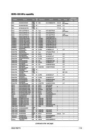
...; • - • • - • • - • • - • • - • • 1.5V • • - • • - • • - • • (continued on the next page) ASUS P8H77-I 1-19 J2108BCSE-DJ-F - H5TQ2G83BFRH9C -
...; • - • • - • • - • • - • • - • • 1.5V • • - • • - • • - • • (continued on the next page) ASUS P8H77-I 1-19 J2108BCSE-DJ-F - H5TQ2G83BFRH9C -
P8H77-I User's Manual
Page 31
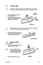
... pressing the retaining clips. Press the retaining clips outward to avoid damaging the DIMM. 3. Locked Retaining Clip 2 1 2. Remove the DIMM from the socket. DIMM notch ASUS P8H77-I 1-21 1.7.3 Installing a DIMM Unplug the power supply before adding or removing DIMMs or other system components. Firmly insert the DIMM into a socket in only one...
... pressing the retaining clips. Press the retaining clips outward to avoid damaging the DIMM. 3. Locked Retaining Clip 2 1 2. Remove the DIMM from the socket. DIMM notch ASUS P8H77-I 1-21 1.7.3 Installing a DIMM Unplug the power supply before adding or removing DIMMs or other system components. Firmly insert the DIMM into a socket in only one...
P8H77-I User's Manual
Page 33
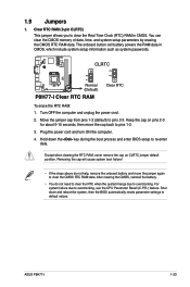
... powers the RAM data in CMOS. Shut down the key during the boot process and enter BIOS setup to clear the CMOS RTC RAM data. ASUS P8H77-I Clear RTC RAM Clear RTC To erase the RTC RAM: 1. Clear RTC RAM (3-pin CLRTC) This jumper allows you to pins 2-3. Plug ...For system failure due to overclocking. Hold down and reboot the system, then the BIOS automatically resets parameter settings to pins 1-2. 3. CLRTC P8H77-I 12 23 Normal (Default) P8H77-I 1-23 You can clear the CMOS memory of date, time, and system setup parameters by erasing the CMOS RTC RAM data. After clearing...
... powers the RAM data in CMOS. Shut down the key during the boot process and enter BIOS setup to clear the CMOS RTC RAM data. ASUS P8H77-I Clear RTC RAM Clear RTC To erase the RTC RAM: 1. Clear RTC RAM (3-pin CLRTC) This jumper allows you to pins 2-3. Plug ...For system failure due to overclocking. Hold down and reboot the system, then the BIOS automatically resets parameter settings to pins 1-2. 3. CLRTC P8H77-I 12 23 Normal (Default) P8H77-I 1-23 You can clear the CMOS memory of date, time, and system setup parameters by erasing the CMOS RTC RAM data. After clearing...
P8H77-I User's Manual
Page 35
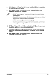
This port is for connecting USB 2.0/1.1 devices. 9. ASUS P8H77-I . 11. 8. These four 4-pin Universal Serial Bus (USB) ports are available for any USB 3.0 port when installing Windows® operating system. • Due to USB 3.0 ...
This port is for connecting USB 2.0/1.1 devices. 9. ASUS P8H77-I . 11. 8. These four 4-pin Universal Serial Bus (USB) ports are available for any USB 3.0 port when installing Windows® operating system. • Due to USB 3.0 ...
P8H77-I User's Manual
Page 37
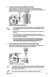
...the fan connectors on the fan connectors! ATX12V EATXPWR +12V DC +12V DC P8H77-I +3 Volts +12 Volts +12 Volts +5V Standby Power OK GND PIN 1 +5 Volts GND +5 Volts GND +3 Volts +3 Volts PIN 1 P8H77-I 1-27 Do not place jumper caps on the motherboard, ensuring that complies ...later version) and provides a minimum power of maximum 2A (24 W) fan power. These are designed to the Recommended Power Supply Wattage Calculator at http://support.asus. ASUS P8H77-I ATX power connectors GND GND GND +5 Volts +5 Volts +5 Volts -5 Volts GND GND GND PSON# GND -12 Volts +3 Volts • For ...
...the fan connectors on the fan connectors! ATX12V EATXPWR +12V DC +12V DC P8H77-I +3 Volts +12 Volts +12 Volts +5V Standby Power OK GND PIN 1 +5 Volts GND +5 Volts GND +3 Volts +3 Volts PIN 1 P8H77-I 1-27 Do not place jumper caps on the motherboard, ensuring that complies ...later version) and provides a minimum power of maximum 2A (24 W) fan power. These are designed to the Recommended Power Supply Wattage Calculator at http://support.asus. ASUS P8H77-I ATX power connectors GND GND GND +5 Volts +5 Volts +5 Volts -5 Volts GND GND GND PSON# GND -12 Volts +3 Volts • For ...
P8H77-I User's Manual
Page 39
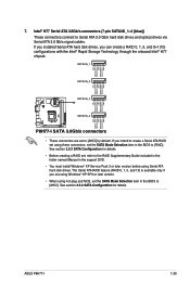
...ATA RAID feature (RAID 0, 1, 5, and 10) is available only if you are set , refer to [RAID]. SATA3G_1 SATA3G_2 SATA3G_3 SATA3G_4 P8H77-I 1-29 If you installed Serial ATA hard disk drives, you intend to create a Serial ATA RAID set using these connectors, set the ...the Intel® Rapid Storage Technology through the onboard Intel® H77 chipset. See section 2.5.3 SATA Configuration for details. P8H77-I GND RSATA_TXP4 RSATA_TXN4 GND RSATA_RXN4 RSATA_RXP4 GND ASUS P8H77-I SATA 3.0Gb/s connectors • These connectors are using Windows® XP SP3 or later version. • When...
...ATA RAID feature (RAID 0, 1, 5, and 10) is available only if you are set , refer to [RAID]. SATA3G_1 SATA3G_2 SATA3G_3 SATA3G_4 P8H77-I 1-29 If you installed Serial ATA hard disk drives, you intend to create a Serial ATA RAID set using these connectors, set the ...the Intel® Rapid Storage Technology through the onboard Intel® H77 chipset. See section 2.5.3 SATA Configuration for details. P8H77-I GND RSATA_TXP4 RSATA_TXN4 GND RSATA_RXN4 RSATA_RXP4 GND ASUS P8H77-I SATA 3.0Gb/s connectors • These connectors are using Windows® XP SP3 or later version. • When...
P8H77-I User's Manual
Page 41
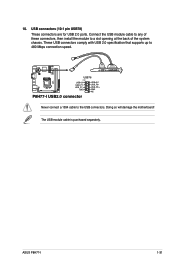
Connect the USB module cable to any of the system chassis. Doing so will damage the motherboard! These USB connectors comply with USB 2.0 specification that supports up to a slot opening at the back of these connectors, then install the module to 480 Mbps connection speed. P8H77-I USB78 PIN 1 USB+5V USB_P7USB_P7+ GND USB+5V USB_P8USB_P8+ GND NC P8H77-I 1-31 ASUS P8H77-I USB2.0 connector Never connect a 1394 cable to the USB connectors. The USB module cable is purchased separately. 10. USB connectors (10-1 pin USB78) These connectors are for USB 2.0 ports.
Connect the USB module cable to any of the system chassis. Doing so will damage the motherboard! These USB connectors comply with USB 2.0 specification that supports up to a slot opening at the back of these connectors, then install the module to 480 Mbps connection speed. P8H77-I USB78 PIN 1 USB+5V USB_P7USB_P7+ GND USB+5V USB_P8USB_P8+ GND NC P8H77-I 1-31 ASUS P8H77-I USB2.0 connector Never connect a 1394 cable to the USB connectors. The USB module cable is purchased separately. 10. USB connectors (10-1 pin USB78) These connectors are for USB 2.0 ports.
P8H77-I User's Manual
Page 43
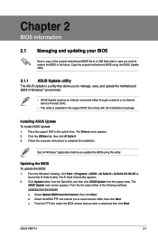
...To update the BIOS: 1. Select the ASUS FTP site nearest you update the BIOS using the ASUS Update utility. 2.1.1 ASUS Update utility The ASUS Update is available in the optical drive. ASUS P8H77-I 2-1 The Drivers menu appears. 2. From the Windows® desktop, click Start > Programs > ASUS > AI Suite II > AI Suite ... select the BIOS version that allows you to manage, save, and update the motherboard BIOS in Windows® environment. • ASUS Update requires an Internet connection either of the original motherboard BIOS file to a USB flash disk in case you wish to restore ...
...To update the BIOS: 1. Select the ASUS FTP site nearest you update the BIOS using the ASUS Update utility. 2.1.1 ASUS Update utility The ASUS Update is available in the optical drive. ASUS P8H77-I 2-1 The Drivers menu appears. 2. From the Windows® desktop, click Start > Programs > ASUS > AI Suite II > AI Suite ... select the BIOS version that allows you to manage, save, and update the motherboard BIOS in Windows® environment. • ASUS Update requires an Internet connection either of the original motherboard BIOS file to a USB flash disk in case you wish to restore ...
P8H77-I User's Manual
Page 45
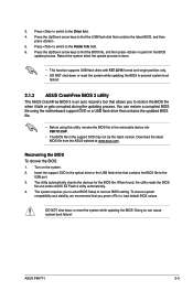
...or reset the system while updating the BIOS to prevent system boot failure! 2.1.3 ASUS CrashFree BIOS 3 utility The ASUS CrashFree BIOS 3 is an auto recovery tool that contains the BIOS file to the Drive field. 4. ASUS P8H77-I 2-3 Reboot the system when the update process is done. • This ... Recovering the BIOS To recover the BIOS: 1. You can cause system boot failure! When found, the utility reads the BIOS file and enters ASUS EZ Flash 2 utility automatically. 4. 3. The utility automatically checks the devices for the BIOS file. Turn on the system. 2. The system requires...
...or reset the system while updating the BIOS to prevent system boot failure! 2.1.3 ASUS CrashFree BIOS 3 utility The ASUS CrashFree BIOS 3 is an auto recovery tool that contains the BIOS file to the Drive field. 4. ASUS P8H77-I 2-3 Reboot the system when the update process is done. • This ... Recovering the BIOS To recover the BIOS: 1. You can cause system boot failure! When found, the utility reads the BIOS file and enters ASUS EZ Flash 2 utility automatically. 4. 3. The utility automatically checks the devices for the BIOS file. Turn on the system. 2. The system requires...
P8H77-I User's Manual
Page 47
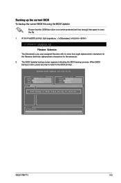
... BIOS Updater backup screen appears indicating the BIOS backup process. ASUSTek BIOS Updater for the extension. 2. Note Saving BIOS: ASUS P8H77-I VER: 0214 DATE: 12/09/2011 Update ROM BOARD: Unknown VER: Unknown DATE: Unknown PATH: A:\ BIOS backup is done, press any key to return to ...
... BIOS Updater backup screen appears indicating the BIOS backup process. ASUSTek BIOS Updater for the extension. 2. Note Saving BIOS: ASUS P8H77-I VER: 0214 DATE: 12/09/2011 Update ROM BOARD: Unknown VER: Unknown DATE: Unknown PATH: A:\ BIOS backup is done, press any key to return to ...
P8H77-I User's Manual
Page 49
... the system fails to boot after changing any BIOS setting, load the default settings to ensure system compatibility and stability. ASUS P8H77-I 2-7 Entering BIOS Setup at startup To enter BIOS Setup at www.asus.com to download the latest BIOS file for this section are for information on your screen. • Visit the... ASUS website at startup: • Press during the Power-On Self Test (POST). Entering BIOS Setup after POST To enter BIOS Setup after changing any BIOS ...
... the system fails to boot after changing any BIOS setting, load the default settings to ensure system compatibility and stability. ASUS P8H77-I 2-7 Entering BIOS Setup at startup To enter BIOS Setup at www.asus.com to download the latest BIOS file for this section are for information on your screen. • Visit the... ASUS website at startup: • Press during the Power-On Self Test (POST). Entering BIOS Setup after POST To enter BIOS Setup after changing any BIOS ...


