User Manual
Page 1
Motherboard P8H61-M LX Series • P8H61-M LX • P8H61-M LX PLUS
Motherboard P8H61-M LX Series • P8H61-M LX • P8H61-M LX PLUS

User Manual
Page 3
Contents Notices...vi Safety information vii About this guide viii P8H61-M LX Series specifications summary ix Chapter 1: Product introduction 1.1 Welcome 1-1 1.2 Package contents 1-1 1.3 Special features 1-1 1.3.1 Product highlights 1-1 1.3.2 Innovative ASUS features 1-2 1.4 Before you proceed 1-5 1.5 Motherboard overview 1-6 1.5.1 Placement direction 1-6 1.5.2 Screw holes 1-6 1.5.3 Motherboard layout 1-7 1.5.4 Layout contents 1-7 1.6 Central Processing Unit (CPU 1-8 1.6.1 Installing the CPU 1-8 1.6.2 Installing the CPU heatsink and fan 1-11...
Contents Notices...vi Safety information vii About this guide viii P8H61-M LX Series specifications summary ix Chapter 1: Product introduction 1.1 Welcome 1-1 1.2 Package contents 1-1 1.3 Special features 1-1 1.3.1 Product highlights 1-1 1.3.2 Innovative ASUS features 1-2 1.4 Before you proceed 1-5 1.5 Motherboard overview 1-6 1.5.1 Placement direction 1-6 1.5.2 Screw holes 1-6 1.5.3 Motherboard layout 1-7 1.5.4 Layout contents 1-7 1.6 Central Processing Unit (CPU 1-8 1.6.1 Installing the CPU 1-8 1.6.2 Installing the CPU heatsink and fan 1-11...
User Manual
Page 7
DO NOT throw the motherboard in municipal waste. This symbol of the crossed out wheeled bin indicates that your power supply is broken, do not try to the correct voltage in our products at ASUS REACH website at http://csr.asus.com/english/REACH.htm. If you are not sure about the... voltage of the electrical outlet you add a device. • Before connecting or removing signal cables from the motherboard, ensure that all cables are correctly connected and...
DO NOT throw the motherboard in municipal waste. This symbol of the crossed out wheeled bin indicates that your power supply is broken, do not try to the correct voltage in our products at ASUS REACH website at http://csr.asus.com/english/REACH.htm. If you are not sure about the... voltage of the electrical outlet you add a device. • Before connecting or removing signal cables from the motherboard, ensure that all cables are correctly connected and...
User Manual
Page 8
...this guide To ensure that you perform certain tasks properly, take note of the BIOS parameters are linked with a plus sign (+). Detailed descriptions of the following symbols used in the less-than and greater-than sign means that may include...for product and software updates. 1. NOTE: Tips and additional information to the ASUS contact information. 2. ASUS websites The ASUS website provides updated information on ASUS hardware and software products. These documents are not part of the motherboard and the new technology it supports. • Chapter 2: BIOS information This ...
...this guide To ensure that you perform certain tasks properly, take note of the BIOS parameters are linked with a plus sign (+). Detailed descriptions of the following symbols used in the less-than and greater-than sign means that may include...for product and software updates. 1. NOTE: Tips and additional information to the ASUS contact information. 2. ASUS websites The ASUS website provides updated information on ASUS hardware and software products. These documents are not part of the motherboard and the new technology it supports. • Chapter 2: BIOS information This ...
User Manual
Page 11
... great graphics performance. Chapter 1: Product introduction 1-1 Intel® second generation Core™ i7 / Core™ i5 / Core™ i3 processors are for the following items. Motherboard Cables Accessories Application DVD Documentation ASUS P8H61-M LX Series motherboard 2 x Serial ATA 3.0Gb/s cables 1 x I/O shield ASUS motherboard support DVD User Manual • P8H61-M LX Series motherboards include P8H61-M LX PLUS and P8H61-M LX two models.
... great graphics performance. Chapter 1: Product introduction 1-1 Intel® second generation Core™ i7 / Core™ i5 / Core™ i3 processors are for the following items. Motherboard Cables Accessories Application DVD Documentation ASUS P8H61-M LX Series motherboard 2 x Serial ATA 3.0Gb/s cables 1 x I/O shield ASUS motherboard support DVD User Manual • P8H61-M LX Series motherboards include P8H61-M LX PLUS and P8H61-M LX two models.
User Manual
Page 12
...the F12 hotkey BIOS snapshot feature. Innovative ASUS features ASUS UEFI BIOS (EZ Mode) ASUS UEFI BIOS offers a user-friendly interface that demand far more intricate system control, including detailed DRAM information. 1-2 ASUS P8H61-M LX Series The dual-channel DDR3 architecture enlarges ... to provide efficient power management for advanced operating systems. 100% All High-quality Conductive Polymer Capacitors (P8H61-M LX PLUS only) This motherboard uses all high-quality conductive polymer capacitors for double speed and bandwidth which enhances system performance. 8-channel...
...the F12 hotkey BIOS snapshot feature. Innovative ASUS features ASUS UEFI BIOS (EZ Mode) ASUS UEFI BIOS offers a user-friendly interface that demand far more intricate system control, including detailed DRAM information. 1-2 ASUS P8H61-M LX Series The dual-channel DDR3 architecture enlarges ... to provide efficient power management for advanced operating systems. 100% All High-quality Conductive Polymer Capacitors (P8H61-M LX PLUS only) This motherboard uses all high-quality conductive polymer capacitors for double speed and bandwidth which enhances system performance. 8-channel...
User Manual
Page 13
...from switching power supply (PSU). ESD Protect Your Computer with the elegant appearance! ASUS ESD Guards clamp the ESD voltage and shunt the majority of the ESD current away for motherboard users, but also effectively cools down hot airflows generated by the northbridge chipset. Chapter... 1: Product introduction 1-3 This all the exclusive ASUS features into one software offers diverse and ease to supervise ...
...from switching power supply (PSU). ESD Protect Your Computer with the elegant appearance! ASUS ESD Guards clamp the ESD voltage and shunt the majority of the ESD current away for motherboard users, but also effectively cools down hot airflows generated by the northbridge chipset. Chapter... 1: Product introduction 1-3 This all the exclusive ASUS features into one software offers diverse and ease to supervise ...
User Manual
Page 14
...motherboard is a utility that allows you to update the BIOS without using the bundled support DVD or USB flash disk that allows you to restore a corrupted BIOS file using an OS-based utility. ASUS MyLogo2™ This feature allows you to energy consumptions. ASUS EZ Flash 2 ASUS... products to meet certain energy efficiency requirements in line with ASUS vision of the product and thus mitigate environmental impacts. 1-4 ASUS P8H61-M LX Series C.P.R. (CPU Parameter Recall) The BIOS C.P.R. ASUS CrashFree BIOS 3 ASUS CrashFree BIOS 3 is in regards to convert your favorite ...
...motherboard is a utility that allows you to update the BIOS without using the bundled support DVD or USB flash disk that allows you to restore a corrupted BIOS file using an OS-based utility. ASUS MyLogo2™ This feature allows you to energy consumptions. ASUS EZ Flash 2 ASUS... products to meet certain energy efficiency requirements in line with ASUS vision of the product and thus mitigate environmental impacts. 1-4 ASUS P8H61-M LX Series C.P.R. (CPU Parameter Recall) The BIOS C.P.R. ASUS CrashFree BIOS 3 ASUS CrashFree BIOS 3 is in regards to convert your favorite ...
User Manual
Page 15
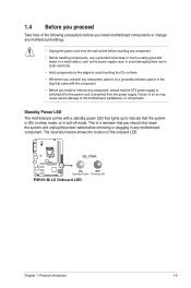
... may cause severe damage to indicate that the system is ON, in sleep mode, or in any motherboard settings. • Unplug the power cord from the power supply. SB_PWR P8H61-M LX ON OFF Standby Power Powered Off P8H61-M LX Onboard LED Chapter 1: Product introduction 1-5 1.4 Before you proceed Take note of the onboard LED. The illustration...
... may cause severe damage to indicate that the system is ON, in sleep mode, or in any motherboard settings. • Unplug the power cord from the power supply. SB_PWR P8H61-M LX ON OFF Standby Power Powered Off P8H61-M LX Onboard LED Chapter 1: Product introduction 1-5 1.4 Before you proceed Take note of the onboard LED. The illustration...

User Manual
Page 16
...the rear part of the chassis P8H61-M LX 1-6 ASUS P8H61-M LX Series Do not overtighten the screws! Failure to do so can damage the motherboard. Doing so can cause you physical injury and damage motherboard components. 1.5.1 Placement direction When installing the motherboard, ensure that you unplug the ...chassis as indicated in the correct orientation. Ensure that you place it . 1.5 Motherboard overview Before you install the motherboard, study the configuration of your chassis to ensure that the motherboard fits into it into the chassis in the image below. 1.5.2 Screw holes ...
...the rear part of the chassis P8H61-M LX 1-6 ASUS P8H61-M LX Series Do not overtighten the screws! Failure to do so can damage the motherboard. Doing so can cause you physical injury and damage motherboard components. 1.5.1 Placement direction When installing the motherboard, ensure that you unplug the ...chassis as indicated in the correct orientation. Ensure that you place it . 1.5 Motherboard overview Before you install the motherboard, study the configuration of your chassis to ensure that the motherboard fits into it into the chassis in the image below. 1.5.2 Screw holes ...
User Manual
Page 17
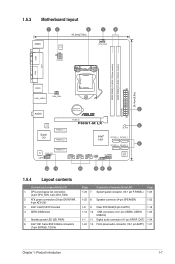
... connectors (24-pin EATXPWR, 4-pin ATX12V) 3. 1.5.3 Motherboard layout 12 3 19.3cm(7.6in) KBMS EPU 1 4 CPU_FAN COM ATX12V DDR3 DIMM_A1 (64bit, 240-pin module) DDR3 DIMM_B1 (64bit, 240-pin module) LPT VGA LGA1155 24.4cm(9.6in) USB34 LAN1_USB12 CHA_FAN EATXPWR Lithium Cell CMOS Power 2 AUDIO PCIEX16 P8H61-M LX RTL 8111E PCIEX1_1 5 SB_PWR Super I/O PCIEX1_2...
... connectors (24-pin EATXPWR, 4-pin ATX12V) 3. 1.5.3 Motherboard layout 12 3 19.3cm(7.6in) KBMS EPU 1 4 CPU_FAN COM ATX12V DDR3 DIMM_A1 (64bit, 240-pin module) DDR3 DIMM_B1 (64bit, 240-pin module) LPT VGA LGA1155 24.4cm(9.6in) USB34 LAN1_USB12 CHA_FAN EATXPWR Lithium Cell CMOS Power 2 AUDIO PCIEX16 P8H61-M LX RTL 8111E PCIEX1_1 5 SB_PWR Super I/O PCIEX1_2...
User Manual
Page 18
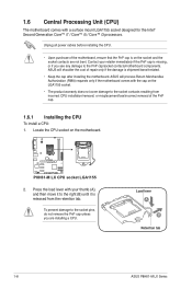
...-related. • Keep the cap after installing the motherboard. Load lever A B Retention tab 1-8 ASUS P8H61-M LX Series Locate the CPU socket on the socket and the socket contacts are installing a CPU. ASUS will shoulder the cost of the motherboard, ensure that the PnP cap is on the motherboard. ASUS will process Return Merchandise Authorization (RMA) requests only if...
...-related. • Keep the cap after installing the motherboard. Load lever A B Retention tab 1-8 ASUS P8H61-M LX Series Locate the CPU socket on the socket and the socket contacts are installing a CPU. ASUS will shoulder the cost of the motherboard, ensure that the PnP cap is on the motherboard. ASUS will process Return Merchandise Authorization (RMA) requests only if...
User Manual
Page 21
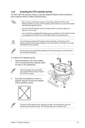
Chapter 1: Product introduction 1-11 The LGA1155 socket is for reference only. Place the heatsink on the motherboard. A B 1 1 B A The type of the installed CPU, ensuring that the CPU fan cable is closest to the CPU fan connector. 2. The illustration above ...sequence to secure the heatsink and fan assembly in place. If you purchased a separate CPU heatsink and fan assembly, ensure that you have installed the motherboard to the chassis before you install the heatsink and fan assembly. B B Orient the heatsink and fan assembly A such that the four fasteners match...
Chapter 1: Product introduction 1-11 The LGA1155 socket is for reference only. Place the heatsink on the motherboard. A B 1 1 B A The type of the installed CPU, ensuring that the CPU fan cable is closest to the CPU fan connector. 2. The illustration above ...sequence to secure the heatsink and fan assembly in place. If you purchased a separate CPU heatsink and fan assembly, ensure that you have installed the motherboard to the chassis before you install the heatsink and fan assembly. B B Orient the heatsink and fan assembly A such that the four fasteners match...
User Manual
Page 22
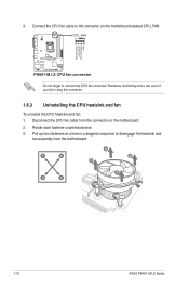
... CPU fan cable to disengage the heatsink and fan assembly from the connector on the motherboard labeled CPU_FAN. Rotate each fastener counterclockwise. 3. Pull up two fasteners at a time in a diagonal sequence to the connector on the motherboard. 2. A B A B B A B A 1-12 ASUS P8H61-M LX Series Hardware monitoring errors can occur if you fail to connect the CPU fan...
... CPU fan cable to disengage the heatsink and fan assembly from the connector on the motherboard labeled CPU_FAN. Rotate each fastener counterclockwise. 3. Pull up two fasteners at a time in a diagonal sequence to the connector on the motherboard. 2. A B A B B A B A 1-12 ASUS P8H61-M LX Series Hardware monitoring errors can occur if you fail to connect the CPU fan...
User Manual
Page 23
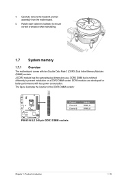
... socket. The figure illustrates the location of the DDR3 DIMM sockets: DIMM_A1 DIMM_B1 P8H61-M LX Channel Channel A Channel B Sockets DIMM_A1 DIMM_B1 P8H61-M LX 240-pin DDR3 DIMM sockets Chapter 1: Product introduction 1-13 4. Carefully remove the heatsink and fan assembly from the motherboard. 5. A DDR3 module has the same physical dimensions as a DDR2 DIMM but is notched...
... socket. The figure illustrates the location of the DDR3 DIMM sockets: DIMM_A1 DIMM_B1 P8H61-M LX Channel Channel A Channel B Sockets DIMM_A1 DIMM_B1 P8H61-M LX 240-pin DDR3 DIMM sockets Chapter 1: Product introduction 1-13 4. Carefully remove the heatsink and fan assembly from the motherboard. 5. A DDR3 module has the same physical dimensions as a DDR2 DIMM but is notched...
User Manual
Page 24
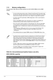
... • Micron MT16JTF25664AZ-1G1F1 2GB DS Micron 9HF22D9KPT 7 - • • 1-14 ASUS P8H61-M LX Series Use a maximum of 3GB system memory if you install 4GB or more on the motherboard. • This motherboard does not support DIMMs made up of 512Mb (64MB) chips or less. • The...; According to Intel CPU specification, DIMM voltage below 1.65V is dependent on the motherboard, the actual usable memory for the OS can be about 3GB or less. P8H61-M LX Series Motherboard Qualified Vendors Lists (QVL) DDR3-1066 MHz capability Vendors Part No. 1.7.2 Memory configurations...
... • Micron MT16JTF25664AZ-1G1F1 2GB DS Micron 9HF22D9KPT 7 - • • 1-14 ASUS P8H61-M LX Series Use a maximum of 3GB system memory if you install 4GB or more on the motherboard. • This motherboard does not support DIMMs made up of 512Mb (64MB) chips or less. • The...; According to Intel CPU specification, DIMM voltage below 1.65V is dependent on the motherboard, the actual usable memory for the OS can be about 3GB or less. P8H61-M LX Series Motherboard Qualified Vendors Lists (QVL) DDR3-1066 MHz capability Vendors Part No. 1.7.2 Memory configurations...
User Manual
Page 27
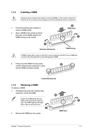
... unlock the DIMM. 2 Support the DIMM lightly with extra force. 1 2. The DIMM might get damaged when it fits in the wrong direction to both the motherboard and the components. 1. Align a DIMM on the socket. 2 DIMM notch 1 1 Unlocked retaining clip DIMM slot key A DIMM is properly seated. Simultaneously press the retaining clips...
... unlock the DIMM. 2 Support the DIMM lightly with extra force. 1 2. The DIMM might get damaged when it fits in the wrong direction to both the motherboard and the components. 1. Align a DIMM on the socket. 2 DIMM notch 1 1 Unlocked retaining clip DIMM slot key A DIMM is properly seated. Simultaneously press the retaining clips...
User Manual
Page 28
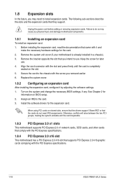
... other cards that comply with the PCI Express specifications. 1.8.4 PCI Express 2.0 x16 slot This motherboard has a PCI Express 2.0 x16 slot that came with the PCI Express specifications. 1-18 ASUS P8H61-M LX Series Remove the bracket opposite the slot that they support. Secure the card to use .... firmly until the card is already installed in a chassis). 3. Align the card connector with the screw you physical injury and damage motherboard components. 1.8.1 Installing an expansion card To install an expansion card: 1. 1.8 Expansion slots In the future, you may cause you removed...
... other cards that comply with the PCI Express specifications. 1.8.4 PCI Express 2.0 x16 slot This motherboard has a PCI Express 2.0 x16 slot that came with the PCI Express specifications. 1-18 ASUS P8H61-M LX Series Remove the bracket opposite the slot that they support. Secure the card to use .... firmly until the card is already installed in a chassis). 3. Align the card connector with the screw you physical injury and damage motherboard components. 1.8.1 Installing an expansion card To install an expansion card: 1. 1.8 Expansion slots In the future, you may cause you removed...

User Manual
Page 31
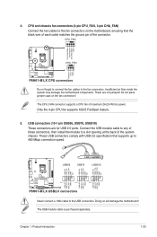
...details. This port is for USB 2.0/1.1 devices. 8. PS/2 Keyboard (Purple). 7. USB 2.0 ports 1 and 2. Connect one end of the motherboard's high-definition audio capability. • If you want to connect a high-definition front panel audio module to this connector is for USB 2.0/1.1 devices... PIN 1 MIC2 MICPWR Line out_R NC Line out_L PORT1 L PORT1 R PORT2 R SENSE_SEND PORT2 L P8H61-M LX HD-audio-compliant Legacy AC'97 pin definition compliant definition P8H61-M LX Front panel audio connector • We recommend that supports either HD Audio or legacy AC`97 audio ...
...details. This port is for USB 2.0/1.1 devices. 8. PS/2 Keyboard (Purple). 7. USB 2.0 ports 1 and 2. Connect one end of the motherboard's high-definition audio capability. • If you want to connect a high-definition front panel audio module to this connector is for USB 2.0/1.1 devices... PIN 1 MIC2 MICPWR Line out_R NC Line out_L PORT1 L PORT1 R PORT2 R SENSE_SEND PORT2 L P8H61-M LX HD-audio-compliant Legacy AC'97 pin definition compliant definition P8H61-M LX Front panel audio connector • We recommend that supports either HD Audio or legacy AC`97 audio ...
User Manual
Page 33
...+ GND NC USB+5V USB_P8USB_P8+ GND NC USB+5V USB_P10USB_P10+ GND NC P8H61-M LX PIN 1 PIN 1 PIN 1 USB+5V USB_P5USB_P5+ GND USB+5V USB_P7USB_P7+ GND USB+5V USB_P9USB_P9+ GND P8H61-M LX USB2.0 connectors Never connect a 1394 cable to the fan connectors. The CPU_FAN...USB910) These connectors are not jumpers! Doing so will damage the motherboard! Chapter 1: Product introduction 1-23 Insufficient air flow inside the system may damage the motherboard components. Only the 4-pin CPU fan supports ASUS FanXpert feature. 5. These USB connectors comply with USB 2.0 specification...
...+ GND NC USB+5V USB_P8USB_P8+ GND NC USB+5V USB_P10USB_P10+ GND NC P8H61-M LX PIN 1 PIN 1 PIN 1 USB+5V USB_P5USB_P5+ GND USB+5V USB_P7USB_P7+ GND USB+5V USB_P9USB_P9+ GND P8H61-M LX USB2.0 connectors Never connect a 1394 cable to the fan connectors. The CPU_FAN...USB910) These connectors are not jumpers! Doing so will damage the motherboard! Chapter 1: Product introduction 1-23 Insufficient air flow inside the system may damage the motherboard components. Only the 4-pin CPU fan supports ASUS FanXpert feature. 5. These USB connectors comply with USB 2.0 specification...


