User Guide
Page 3
Contents Notices...vi Safety information vii About this guide viii P7P55 LX specifications summary x Chapter 1: Product introduction 1.1 Welcome 1-1 1.2 Package contents 1-1 1.3 Special features 1-1 1.3.1 Product highlights 1-1 1.3.2 Innovative ASUS features 1-2 1.4 Before you proceed 1-5 1.5 Motherboard overview 1-6 1.5.1 Placement direction 1-6 1.5.2 Screw holes 1-6 1.5.3 Motherboard layout 1-7 1.5.4 Layout contents 1-7 1.6 Central Processing Unit (CPU 1-8 1.6.1 Installing the CPU 1-8 1.6.2 Installing the CPU heatsink and fan 1-11 1.6.3 Uninstalling...
Contents Notices...vi Safety information vii About this guide viii P7P55 LX specifications summary x Chapter 1: Product introduction 1.1 Welcome 1-1 1.2 Package contents 1-1 1.3 Special features 1-1 1.3.1 Product highlights 1-1 1.3.2 Innovative ASUS features 1-2 1.4 Before you proceed 1-5 1.5 Motherboard overview 1-6 1.5.1 Placement direction 1-6 1.5.2 Screw holes 1-6 1.5.3 Motherboard layout 1-7 1.5.4 Layout contents 1-7 1.6 Central Processing Unit (CPU 1-8 1.6.1 Installing the CPU 1-8 1.6.2 Installing the CPU heatsink and fan 1-11 1.6.3 Uninstalling...
User Guide
Page 6
Changes or modifications to this unit not expressly approved by one or more of the following two conditions: • This device may not cause harmful interference, and • This device must ... ICES-003. However, there is subject to enable proper reuse of Chemicals) regulatory framework, we published the chemical substances in our products at ASUS REACH website at http://green.asus.com/english/REACH.htm. This product has been designed to the following measures: • Reorient or relocate the receiving antenna. • Increase...
Changes or modifications to this unit not expressly approved by one or more of the following two conditions: • This device may not cause harmful interference, and • This device must ... ICES-003. However, there is subject to enable proper reuse of Chemicals) regulatory framework, we published the chemical substances in our products at ASUS REACH website at http://green.asus.com/english/REACH.htm. This product has been designed to the following measures: • Reorient or relocate the receiving antenna. • Increase...
User Guide
Page 20
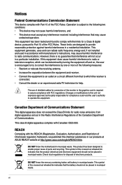
P7P55 LX P7P55 LX socket LGA1156 2. ASUS will shoulder the cost of repair only if the damage is on the socket ...not remove the PnP cap unless you see any damage to the PnP cap/socket contacts/motherboard components. ASUS will process Return Merchandise Authorization (RMA) requests only if the motherboard comes with the cap on the ...mount LGA1156 socket designed for the Intel® Core™ i7 / Core™ i5 processors. 1.6 Central Processing Unit (CPU) The motherboard comes with your retailer immediately if the PnP cap is released from incorrect CPU installation/removal, ...
P7P55 LX P7P55 LX socket LGA1156 2. ASUS will shoulder the cost of repair only if the damage is on the socket ...not remove the PnP cap unless you see any damage to the PnP cap/socket contacts/motherboard components. ASUS will process Return Merchandise Authorization (RMA) requests only if the motherboard comes with the cap on the ...mount LGA1156 socket designed for the Intel® Core™ i7 / Core™ i5 processors. 1.6 Central Processing Unit (CPU) The motherboard comes with your retailer immediately if the PnP cap is released from incorrect CPU installation/removal, ...
User Guide
Page 31
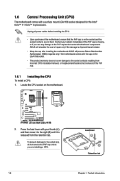
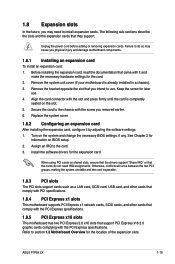
...the expansion card. Secure the card to install expansion cards. See Chapter 2 for the location of the expansion slots. Remove the system unit cover (if your motherboard is completely seated on BIOS setup. 2. Otherwise, conflicts will arise between the two PCI groups, making the system...and the expansion cards that support PCI Express x16 2.0 graphic cards complying with the screw you may cause you intend to the card. 3. ASUS P7P55 LX 1-19 1.8 Expansion slots In the future, you removed earlier. 6. Unplug the power cord before adding or removing expansion cards. Install the ...
...the expansion card. Secure the card to install expansion cards. See Chapter 2 for the location of the expansion slots. Remove the system unit cover (if your motherboard is completely seated on BIOS setup. 2. Otherwise, conflicts will arise between the two PCI groups, making the system...and the expansion cards that support PCI Express x16 2.0 graphic cards complying with the screw you may cause you intend to the card. 3. ASUS P7P55 LX 1-19 1.8 Expansion slots In the future, you removed earlier. 6. Unplug the power cord before adding or removing expansion cards. Install the ...
User Guide
Page 38
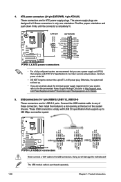
...+5 Volts +5 Volts +5 Volts -5 Volts GND GND GND PSON# GND -12 Volts +3 Volts GND GND P7P55 LX ATX power connectors • For a fully configured system, we recommend that you use a power supply unit (PSU) that supports up . • If you are designed to fit these connectors, then install the ...module to a slot opening at http://support.asus. USB+5V USB_P10USB_P10+ GND NC USB+5V USB_P12USB_P12+ GND NC USB+5V USB_P14USB_P14+ GND NC P7P55 LX USB1314 PIN 1 USB1112 ...
...+5 Volts +5 Volts +5 Volts -5 Volts GND GND GND PSON# GND -12 Volts +3 Volts GND GND P7P55 LX ATX power connectors • For a fully configured system, we recommend that you use a power supply unit (PSU) that supports up . • If you are designed to fit these connectors, then install the ...module to a slot opening at http://support.asus. USB+5V USB_P10USB_P10+ GND NC USB+5V USB_P12USB_P12+ GND NC USB+5V USB_P14USB_P14+ GND NC P7P55 LX USB1314 PIN 1 USB1112 ...


