
User Guide
Page 4
...PCI Express 2.0 x16 slots 2-22 2.6 Jumpers 2-24 2.7 Onboard switches 2-26 2.8 Connectors 2-27 2.8.1 Rear panel connectors 2-27 2.8.2 Internal connectors 2-29 2.9 Installing the additional heatsink fan 2-40 2.10 Starting up for ...11.2 Using the dual function power switch 2-42 Chapter 3: BIOS setup 3.1 Managing and updating your BIOS 3-1 3.1.1 ASUS Update utility 3-1 3.1.2 ASUS EZ Flash 2 utility 3-4 3.1.3 Creating a bootable floppy disk 3-5 3.1.4 AFUDOS utility 3-6 3.1.5 ASUS CrashFree BIOS 3 utility 3-8 3.2 BIOS setup program 3-9 3.2.1 BIOS menu screen 3-10 3.2.2 Menu bar 3-10 ...
...PCI Express 2.0 x16 slots 2-22 2.6 Jumpers 2-24 2.7 Onboard switches 2-26 2.8 Connectors 2-27 2.8.1 Rear panel connectors 2-27 2.8.2 Internal connectors 2-29 2.9 Installing the additional heatsink fan 2-40 2.10 Starting up for ...11.2 Using the dual function power switch 2-42 Chapter 3: BIOS setup 3.1 Managing and updating your BIOS 3-1 3.1.1 ASUS Update utility 3-1 3.1.2 ASUS EZ Flash 2 utility 3-4 3.1.3 Creating a bootable floppy disk 3-5 3.1.4 AFUDOS utility 3-6 3.1.5 ASUS CrashFree BIOS 3 utility 3-8 3.2 BIOS setup program 3-9 3.2.1 BIOS menu screen 3-10 3.2.2 Menu bar 3-10 ...
User Guide
Page 12
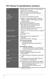
.../s ports - ASUS Noise Filter (continued on the next page) xii Supports Jack-Detection, Multi-streaming, and Front Panel Jack-Retasking technology - Intel® Matrix Storage supporting SATA RAID 0,1, 5, and 10 Marvell 88SE6111 controller: - 1 x Ultra DMA 133/100/66 for Intel CPU support list Intel® X58 / ICH10R Up to 6.4GT/s; P6T Deluxe V2 specifications summary...
.../s ports - ASUS Noise Filter (continued on the next page) xii Supports Jack-Detection, Multi-streaming, and Front Panel Jack-Retasking technology - Intel® Matrix Storage supporting SATA RAID 0,1, 5, and 10 Marvell 88SE6111 controller: - 1 x Ultra DMA 133/100/66 for Intel CPU support list Intel® X58 / ICH10R Up to 6.4GT/s; P6T Deluxe V2 specifications summary...

User Guide
Page 14
P6T Deluxe V2 specifications summary Back Panel I/O Ports Internal I/O Connectors BIOS Features Manageability Support DVD Contents Form Factor 1 x PS/2 Keyboard / Mouse combo port 1 x S/PDIF Out (Coaxial + Optical) 1 x External SATA 1 x IEEE1394a 2 x RJ45 ports 8 x ... switch 16 Mb AMI BIOS, PnP, DMI 2.0, WfM 2.0, SM BIOS 2.4, Multi-language BIOS WOL by PME, WOR by PME, Chassis Intrusion, PXE Drivers ASUS PC Probe II ASUS Update ASUS AI Suite Image-Editing Suite Anti-virus software (OEM version) ATX Form Factor, 12"x 9.6" (30.5cm x 24.4cm) *Specifications are subject to change...
P6T Deluxe V2 specifications summary Back Panel I/O Ports Internal I/O Connectors BIOS Features Manageability Support DVD Contents Form Factor 1 x PS/2 Keyboard / Mouse combo port 1 x S/PDIF Out (Coaxial + Optical) 1 x External SATA 1 x IEEE1394a 2 x RJ45 ports 8 x ... switch 16 Mb AMI BIOS, PnP, DMI 2.0, WfM 2.0, SM BIOS 2.4, Multi-language BIOS WOL by PME, WOR by PME, Chassis Intrusion, PXE Drivers ASUS PC Probe II ASUS Update ASUS AI Suite Image-Editing Suite Anti-virus software (OEM version) ATX Form Factor, 12"x 9.6" (30.5cm x 24.4cm) *Specifications are subject to change...
User Guide
Page 17
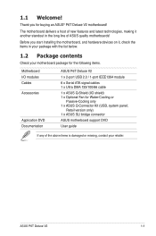
ASUS P6T Deluxe V2 1-1 Retail version only) 1 x ASUS SLI bridge connector ASUS motherboard support DVD User guide If any of ASUS quality motherboards! Before you for Water-Cooling or Passive-Cooling only 1 x ASUS Q-Connector Kit (USB, system panel; Thank you start installing the motherboard, and hardware devices on it another ...contact your motherboard package for the following items. Motherboard I/O modules Cables Accessories Application DVD Documentation ASUS P6T Deluxe V2 1 x 2-port USB 2.0 / 1-port IEEE1394 module 6 x Serial ATA signal cables 1 x Ultra DMA 133/100/66 cable...
ASUS P6T Deluxe V2 1-1 Retail version only) 1 x ASUS SLI bridge connector ASUS motherboard support DVD User guide If any of ASUS quality motherboards! Before you for Water-Cooling or Passive-Cooling only 1 x ASUS Q-Connector Kit (USB, system panel; Thank you start installing the motherboard, and hardware devices on it another ...contact your motherboard package for the following items. Motherboard I/O modules Cables Accessories Application DVD Documentation ASUS P6T Deluxe V2 1 x 2-port USB 2.0 / 1-port IEEE1394 module 6 x Serial ATA signal cables 1 x Ultra DMA 133/100/66 cable...

User Guide
Page 22
...users freedom to conveniently store or load multiple BIOS settings. ASUS CrashFree BIOS 3 The ASUS CrashFree BIOS 3 allows users to the motherboard. ASUS Q-Connector ASUS Q-Connector allows you to easily connect or disconnect the chassis front panel cables to restore corrupted BIOS data from a USB flash disk... containing the BIOS file. Profile The motherboard features the ASUS O.C. See page 2-26 for details. See page 2-39 for details. ASUS EZ Flash 2 EZ Flash 2 ...
...users freedom to conveniently store or load multiple BIOS settings. ASUS CrashFree BIOS 3 The ASUS CrashFree BIOS 3 allows users to the motherboard. ASUS Q-Connector ASUS Q-Connector allows you to easily connect or disconnect the chassis front panel cables to restore corrupted BIOS data from a USB flash disk... containing the BIOS file. Profile The motherboard features the ASUS O.C. See page 2-26 for details. See page 2-39 for details. ASUS EZ Flash 2 EZ Flash 2 ...
User Guide
Page 28
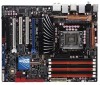
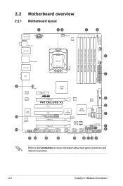
2.2 Motherboard overview 2.2.1 Motherboard layout Refer to 2.8 Connectors for more information about rear panel connectors and internal connectors. 2-2 Chapter 2: Hardware information
2.2 Motherboard overview 2.2.1 Motherboard layout Refer to 2.8 Connectors for more information about rear panel connectors and internal connectors. 2-2 Chapter 2: Hardware information

User Guide
Page 29
...ATX power connectors (24-pin EATXPWR, 8-pin EATX12V) 2. System panel connector (20-8 pin PANEL) 10. DDR3 DIMM slots 5. ICH10R Serial ATA connectors [red] (7-pin SATA1-6) 8. TPM connector (20-1 pin TPM) 11. Front panel audio connector (10-1 pin AAFP) 18. Digital audio connector (4-1... 2-36 2-6 2-34 2-12 2-25 2-30 2-31 2-24 2-38 2-29 2-26 2-35 2-32 2-33 2-29 2-37 2-35 2-37 4-35 ASUS P6T Deluxe V2 2-3 IDE connector (40-1 pin PRI_EIDE) 7. CPU / DRAM Bus / QPI DRAM overvoltage settings (3-pin OV_CPU; 3-pin OV_DRAM_BUS; 3-pin OV_QPI_DRAM) 6. IEEE...
...ATX power connectors (24-pin EATXPWR, 8-pin EATX12V) 2. System panel connector (20-8 pin PANEL) 10. DDR3 DIMM slots 5. ICH10R Serial ATA connectors [red] (7-pin SATA1-6) 8. TPM connector (20-1 pin TPM) 11. Front panel audio connector (10-1 pin AAFP) 18. Digital audio connector (4-1... 2-36 2-6 2-34 2-12 2-25 2-30 2-31 2-24 2-38 2-29 2-26 2-35 2-32 2-33 2-29 2-37 2-35 2-37 4-35 ASUS P6T Deluxe V2 2-3 IDE connector (40-1 pin PRI_EIDE) 7. CPU / DRAM Bus / QPI DRAM overvoltage settings (3-pin OV_CPU; 3-pin OV_DRAM_BUS; 3-pin OV_QPI_DRAM) 6. IEEE...

User Guide
Page 53
... (light blue). Coaxial S/PDIF Out port. This Marvell® LAN port allows Gigabit connection to the table below for the LAN port LED indications. ASUS P6T Deluxe V2 2-27 2.8 Connectors 2.8.1 Rear panel connectors 1. USB 2.0 ports 7 and 8. PS/2 keyboard / mouse combo port. Refer to a Local Area Network (LAN) through a network hub. Rear Speaker Out port (black...
... (light blue). Coaxial S/PDIF Out port. This Marvell® LAN port allows Gigabit connection to the table below for the LAN port LED indications. ASUS P6T Deluxe V2 2-27 2.8 Connectors 2.8.1 Rear panel connectors 1. USB 2.0 ports 7 and 8. PS/2 keyboard / mouse combo port. Refer to a Local Area Network (LAN) through a network hub. Rear Speaker Out port (black...
User Guide
Page 58
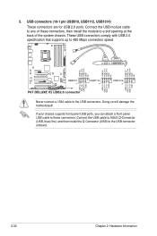
Connect the USB module cable to any of the system chassis. If your chassis suppots front panel USB ports, you can attach a front panel USB cable to these connectors, then install the module to the USB connectors. These USB connectors comply with USB 2.0 specification ...that supports up to the USB connector onboard. 2-32 Chapter 2: Hardware information Connect the USB cable to ASUS Q-Connector (USB, blue) first,...
Connect the USB module cable to any of the system chassis. If your chassis suppots front panel USB ports, you can attach a front panel USB cable to these connectors, then install the module to the USB connectors. These USB connectors comply with USB 2.0 specification ...that supports up to the USB connector onboard. 2-32 Chapter 2: Hardware information Connect the USB cable to ASUS Q-Connector (USB, blue) first,...

User Guide
Page 59
Never connect a USB cable to a slot opening at the back of the system chassis. IEEE 1394a port connector (10-1 pin IE1394_2) This connector is for an IEEE 1394a port. Connect the IEEE 1394a module cable to this connector if your chassis suppots the front panel IEEE1394 port. Doing so will damage the motherboard! You can attach a FireWire/1394 cable to this connector, then install the module to the IEEE 1394a connector. ASUS P6T Deluxe V2 2-33 6.
Never connect a USB cable to a slot opening at the back of the system chassis. IEEE 1394a port connector (10-1 pin IE1394_2) This connector is for an IEEE 1394a port. Connect the IEEE 1394a module cable to this connector if your chassis suppots the front panel IEEE1394 port. Doing so will damage the motherboard! You can attach a FireWire/1394 cable to this connector, then install the module to the IEEE 1394a connector. ASUS P6T Deluxe V2 2-33 6.

User Guide
Page 61
...Signal" and "Ground" are shorted with a jumper cap. ASUS P6T Deluxe V2 2-35 The signal is for a chassis-mounted front panel audio I /O module cable to this connector. • We recommend that you want to connect a high-definition front panel audio module to this connector. Remove the jumper caps only ... is for a chassis-mounted intrusion detection sensor or switch. See page 3-29 or details. If you connect a high-definition front panel audio module to this connector to avail of the chassis intrusion sensor or switch cable to use the chassis intrusion detection feature. 9. ...
...Signal" and "Ground" are shorted with a jumper cap. ASUS P6T Deluxe V2 2-35 The signal is for a chassis-mounted front panel audio I /O module cable to this connector. • We recommend that you want to connect a high-definition front panel audio module to this connector. Remove the jumper caps only ... is for a chassis-mounted intrusion detection sensor or switch. See page 3-29 or details. If you connect a high-definition front panel audio module to this connector to avail of the chassis intrusion sensor or switch cable to use the chassis intrusion detection feature. 9. ...

User Guide
Page 64
... while the system is ON turns the system OFF. • Reset button (2-pin RESET) This 2-pin connector is for the system power LED. System panel connector (20-8 pin PANEL) This connector supports several chassis-mounted functions. • System power LED (2-pin PLED) This 2-pin connector is for the chassis-mounted reset button...
... while the system is ON turns the system OFF. • Reset button (2-pin RESET) This 2-pin connector is for the system power LED. System panel connector (20-8 pin PANEL) This connector supports several chassis-mounted functions. • System power LED (2-pin PLED) This 2-pin connector is for the chassis-mounted reset button...
User Guide
Page 65
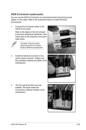
... on the motherboard. ASUS P6T Deluxe V2 2-39 Refer to the respective front panel cable labels. Install the ASUS Q-Connector to connect/disconnect chassis front panel cables in a few steps. The labels of the front panel cables may differ from chassis made by different manufacturers. 2. ASUS Q-Connector (system panel) You can use the ASUS Q-Connector to the system panel connector, making sure...
... on the motherboard. ASUS P6T Deluxe V2 2-39 Refer to the respective front panel cable labels. Install the ASUS Q-Connector to connect/disconnect chassis front panel cables in a few steps. The labels of the front panel cables may differ from chassis made by different manufacturers. 2. ASUS Q-Connector (system panel) You can use the ASUS Q-Connector to the system panel connector, making sure...

User Guide
Page 67
... BIOS Setup. For systems with "green" standards or if it has a "power standby" feature, the monitor LED may have failed a power-on the system front panel case lights up for assistance. BIOS Beep Description One short beep VGA detected Quick boot set to the power connector at the back of the... power on the devices in Chapter 3. If you do not see BIOS beep codes table below) or additional messages appear on self tests or POST. ASUS P6T Deluxe V2 2-41
... BIOS Setup. For systems with "green" standards or if it has a "power standby" feature, the monitor LED may have failed a power-on the system front panel case lights up for assistance. BIOS Beep Description One short beep VGA detected Quick boot set to the power connector at the back of the... power on the devices in Chapter 3. If you do not see BIOS beep codes table below) or additional messages appear on self tests or POST. ASUS P6T Deluxe V2 2-41

User Guide
Page 99
...Enabled] [Disabled] ASUS P6T Deluxe V2 3-29 Configuration options: [Enabled] [Disabled] LAN Boot ROM [Disabled] This item appears only when you enable the previous item. Configuration options: [Enabled] [Disabled] Marvell Storage Boot ROM [Enabled] This item appears only when you set the front panel audio connector (...AAFP) mode to [Enabled]. Configuration options: [Enabled] [Disabled] Front Panel Type [HD Audio] Allows you to set the previous item to legacy AC'97 or...
...Enabled] [Disabled] ASUS P6T Deluxe V2 3-29 Configuration options: [Enabled] [Disabled] LAN Boot ROM [Disabled] This item appears only when you enable the previous item. Configuration options: [Enabled] [Disabled] Marvell Storage Boot ROM [Enabled] This item appears only when you set the front panel audio connector (...AAFP) mode to [Enabled]. Configuration options: [Enabled] [Disabled] Front Panel Type [HD Audio] Allows you to set the previous item to legacy AC'97 or...

User Guide
Page 128
... main window right handle. If Autorun is software-based, you to locate the setup.exe file from the ASUS PC Probe II folder. After launching the application, the PC Probe II icon appears in your system and change... II main window appears. With this icon to close or restore the application. Click the Utilities tab, then click ASUS PC Probe II. 3. By default, the main window displays the Preference section. To launch the PC Probe II from...rotations, CPU temperature, and system voltages, among others. Click to close the Preference panel 4-12 Chapter 4: Software support
... main window right handle. If Autorun is software-based, you to locate the setup.exe file from the ASUS PC Probe II folder. After launching the application, the PC Probe II icon appears in your system and change... II main window appears. With this icon to close or restore the application. Click the Utilities tab, then click ASUS PC Probe II. 3. By default, the main window displays the Preference section. To launch the PC Probe II from...rotations, CPU temperature, and system voltages, among others. Click to close the Preference panel 4-12 Chapter 4: Software support

User Guide
Page 129
... or deactivate. Preference You can customize the application using the Preference section in the main window. Click the box before each preference to the Monitor panels section for that sensor also turns red. Button Function Opens the Configuration window Opens the Report window Opens the Desktop Management Interface window Opens the... Minimizes the application Closes the application Sensor alert When a system sensor detects a problem, the main window right handle turns red, as the illustrations below show. ASUS P6T Deluxe V2 4-13 When displayed, the monitor panel for details.
... or deactivate. Preference You can customize the application using the Preference section in the main window. Click the box before each preference to the Monitor panels section for that sensor also turns red. Button Function Opens the Configuration window Opens the Report window Opens the Desktop Management Interface window Opens the... Minimizes the application Closes the application Sensor alert When a system sensor detects a problem, the main window right handle turns red, as the illustrations below show. ASUS P6T Deluxe V2 4-13 When displayed, the monitor panel for details.

User Guide
Page 130
... the threshold values using a magnetic effect. If you check the Enable Monitoring Panel option from the list box. Click to increase value Click to detach a monitor panel from the group, click the horseshoe magnet icon. Hardware monitor panels The hardware monitor panels display the current value of the Scheme options, then select another position...
... the threshold values using a magnetic effect. If you check the Enable Monitoring Panel option from the list box. Click to increase value Click to detach a monitor panel from the group, click the horseshoe magnet icon. Hardware monitor panels The hardware monitor panels display the current value of the Scheme options, then select another position...

User Guide
Page 131
... the threshold value. Click an item from the left panel to display the DMI (Desktop Management Interface) browser. You can enlarge or reduce the browser size by dragging the bottom right corner of the browser. This browser displays various desktop and system information. ASUS P6T Deluxe V2 4-15 Click the plus sign (+) before WMI Information...
... the threshold value. Click an item from the left panel to display the DMI (Desktop Management Interface) browser. You can enlarge or reduce the browser size by dragging the bottom right corner of the browser. This browser displays various desktop and system information. ASUS P6T Deluxe V2 4-15 Click the plus sign (+) before WMI Information...

User Guide
Page 132
...Hard disk drive space usage The Hard Disk tab displays the used (blue) and the available HDD space. 4-16 Chapter 4: Software support The left panel of the window represents the used and available hard disk drive space. PCI browser Click to display the information on the right... panel. Click a hard disk drive to display the PCI (Peripheral Component Interconnect) browser. The pie chart at the bottom of the tab lists all ...
...Hard disk drive space usage The Hard Disk tab displays the used (blue) and the available HDD space. 4-16 Chapter 4: Software support The left panel of the window represents the used and available hard disk drive space. PCI browser Click to display the information on the right... panel. Click a hard disk drive to display the PCI (Peripheral Component Interconnect) browser. The pie chart at the bottom of the tab lists all ...


