Motherboard Installation Guide
Page 4
... the computer 3-2 3.2.1 Using the OS shut down function 3-2 3.2.2 Using the dual function power switch 3-2 Chapter 4: BIOS setup 4.1 Managing and updating your BIOS 4-1 4.1.1 ASUS Update utility 4-1 4.1.2 Creating a bootable floppy disk 4-4 4.1.3 ASUS EZ Flash 2 utility 4-5 4.1.4 AFUDOS utility 4-6 4.1.5 ASUS CrashFree BIOS 3 utility 4-8 4.2 BIOS setup program 4-9 4.2.1 BIOS menu screen 4-10 4.2.2 Menu bar 4-10 4.2.3 Navigation keys 4-10 4.2.4 Menu items 4-11 4.2.5 Sub-menu items...
... the computer 3-2 3.2.1 Using the OS shut down function 3-2 3.2.2 Using the dual function power switch 3-2 Chapter 4: BIOS setup 4.1 Managing and updating your BIOS 4-1 4.1.1 ASUS Update utility 4-1 4.1.2 Creating a bootable floppy disk 4-4 4.1.3 ASUS EZ Flash 2 utility 4-5 4.1.4 AFUDOS utility 4-6 4.1.5 ASUS CrashFree BIOS 3 utility 4-8 4.2 BIOS setup program 4-9 4.2.1 BIOS menu screen 4-10 4.2.2 Menu bar 4-10 4.2.3 Navigation keys 4-10 4.2.4 Menu items 4-11 4.2.5 Sub-menu items...

Motherboard Installation Guide
Page 10
It includes description of the switches, jumpers, and connectors on ASUS hardware and software products. Detailed descriptions of the BIOS parameters are not part of the motherboard and the new technology it supports. • Chapter 2: Hardware information ... provided. • Chapter 5: Software support This chapter describes the contents of shutting down the system. • Chapter 4: BIOS setup This chapter tells how to the ASUS contact information. 2. About this guide is organized This guide contains the following sources for additional information and for product and software...
It includes description of the switches, jumpers, and connectors on ASUS hardware and software products. Detailed descriptions of the BIOS parameters are not part of the motherboard and the new technology it supports. • Chapter 2: Hardware information ... provided. • Chapter 5: Software support This chapter describes the contents of shutting down the system. • Chapter 4: BIOS setup This chapter tells how to the ASUS contact information. 2. About this guide is organized This guide contains the following sources for additional information and for product and software...
Motherboard Installation Guide
Page 13
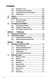
... Power Design - vCore: Adjustable CPU voltage at 1MHz increment Overclocking Protection: - ASUS O.C. ASUS C.P.R. (CPU Parameter Recall) (continued on the next page) xiii ASUS EPU (Energy Processing Unit) - ASUS AI Slot Detector ASUS MyLogo 2 Multi-language BIOS Intelligent overclocking tools: - ASUS Fanless Design: Pure Copper Heat-pipe solution - ASUS Q-Connector - P5E64 WS Evolution specifications AI Lifestyle Unique Features Other Features...
... Power Design - vCore: Adjustable CPU voltage at 1MHz increment Overclocking Protection: - ASUS O.C. ASUS C.P.R. (CPU Parameter Recall) (continued on the next page) xiii ASUS EPU (Energy Processing Unit) - ASUS AI Slot Detector ASUS MyLogo 2 Multi-language BIOS Intelligent overclocking tools: - ASUS Fanless Design: Pure Copper Heat-pipe solution - ASUS Q-Connector - P5E64 WS Evolution specifications AI Lifestyle Unique Features Other Features...
Motherboard Installation Guide
Page 14
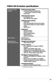
P5E64 WS Evolution specifications Internal connectors Rear panel connectors BIOS features Manageability Support DVD contents Form factor 3 x USB connectors support six additional USB ports 1 x Floppy disk drive connector 1 x IDE connector 6 x Serial ATA ... 2.0/1.1 ports 8-channel audio ports 16 Mb Flash ROM, AMI BIOS, PnP, DMI 2.0, WfM2.0, SMBIOS 2.3, ACPI 2.0a, ASUS EZ Flash 2, ASUS CrashFree BIOS 3 WOL by PME, WOR by PME, PXE, AI NET 2, Chassis Intrusion, BIOS flash utility under DOS Drivers ASUS PC Probe II ASUS AI Suite Anti-virus software Adobe Acrobat Reader ver 7.0 Microsoft Direct...
P5E64 WS Evolution specifications Internal connectors Rear panel connectors BIOS features Manageability Support DVD contents Form factor 3 x USB connectors support six additional USB ports 1 x Floppy disk drive connector 1 x IDE connector 6 x Serial ATA ... 2.0/1.1 ports 8-channel audio ports 16 Mb Flash ROM, AMI BIOS, PnP, DMI 2.0, WfM2.0, SMBIOS 2.3, ACPI 2.0a, ASUS EZ Flash 2, ASUS CrashFree BIOS 3 WOL by PME, WOR by PME, PXE, AI NET 2, Chassis Intrusion, BIOS flash utility under DOS Drivers ASUS PC Probe II ASUS AI Suite Anti-virus software Adobe Acrobat Reader ver 7.0 Microsoft Direct...
Motherboard Installation Guide
Page 22
... at a time and avoiding wrong cable connections. See page 2-36 for details. See page 5-24 to install computer components, update the BIOS or back up your favorite settings. ASUS EZ DIY ASUS EZ DIY feature collection provides you easy ways to 5-32 for details. See page 5-27 and 5-32 for details. 1-6 Chapter 1: Product...
... at a time and avoiding wrong cable connections. See page 2-36 for details. See page 5-24 to install computer components, update the BIOS or back up your favorite settings. ASUS EZ DIY ASUS EZ DIY feature collection provides you easy ways to 5-32 for details. See page 5-27 and 5-32 for details. 1-6 Chapter 1: Product...
Motherboard Installation Guide
Page 23
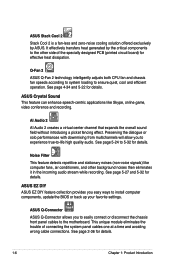
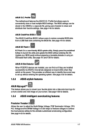
... can find out if they are installed, you to set up without entering the OS. ASUS EZ Flash 2 EZ Flash 2 is a user-friendly BIOS update utility. ASUS P5E64 WS Evolution 1-7 ASUS O.C. Profile The motherboard features the ASUS O.C. Simply press the predefined hotkey to achieve the most precise setting for a more colorful and vivid image on the...
... can find out if they are installed, you to set up without entering the OS. ASUS EZ Flash 2 EZ Flash 2 is a user-friendly BIOS update utility. ASUS P5E64 WS Evolution 1-7 ASUS O.C. Profile The motherboard features the ASUS O.C. Simply press the predefined hotkey to achieve the most precise setting for a more colorful and vivid image on the...

Motherboard Installation Guide
Page 24
eliminates the need to the chipset behavior, AC power off is required before using C.P.R. function. 1-8 Chapter 1: Product Introduction Simply shut down and reboot the system, and the BIOS automatically restores the CPU default setting for each parameter. Due to open the system chassis and clear the RTC data. When the system hangs due to overclocking. C.P.R. (CPU Parameter Recall) The C.P.R. feature of the motherboard BIOS allows automatic re-setting to the BIOS default settings in case the system hangs due to overclocking, C.P.R.
eliminates the need to the chipset behavior, AC power off is required before using C.P.R. function. 1-8 Chapter 1: Product Introduction Simply shut down and reboot the system, and the BIOS automatically restores the CPU default setting for each parameter. Due to open the system chassis and clear the RTC data. When the system hangs due to overclocking. C.P.R. (CPU Parameter Recall) The C.P.R. feature of the motherboard BIOS allows automatic re-setting to the BIOS default settings in case the system hangs due to overclocking, C.P.R.

Motherboard Installation Guide
Page 29
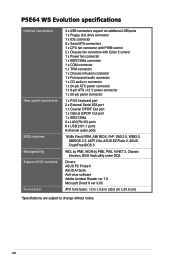
ASUS P5E64 WS Evolution 2-3 30.5cm (12.0in) 2.2.3 Motherboard layout 24.5cm (9.6in) KB_USB56...ADI 1988B VIA VT6308S AAFP DET_X4_1 CHA_FAN1 PCIEX4_1 ® DET_X16_1 PCIEX16_1 DET_X16_2 PCIEX16_2 DET_PCI1 PCI1 DET_X16_3 P5E64 WS EVOLUTION PCIEX16_3 DET_PCI2 PCI2 DET_X16_4 PCIEX16_4 IE1394_2 COM1 CHA_FAN3 CR2032 3V Lithium Cell CMOS Power USB910 USB78 PEX8518 ...88E6145 SATA_E2 SATA_E1 SATA2 SATA1 SATA4 SATA3 Intel® ICH9R SATA6 SATA5 BIOS CHA_FAN2 CLRTC CHASSIS PANEL SB_PWR TPM Refer to 2.7 Connectors for more information about rear panel connectors and ...
ASUS P5E64 WS Evolution 2-3 30.5cm (12.0in) 2.2.3 Motherboard layout 24.5cm (9.6in) KB_USB56...ADI 1988B VIA VT6308S AAFP DET_X4_1 CHA_FAN1 PCIEX4_1 ® DET_X16_1 PCIEX16_1 DET_X16_2 PCIEX16_2 DET_PCI1 PCI1 DET_X16_3 P5E64 WS EVOLUTION PCIEX16_3 DET_PCI2 PCI2 DET_X16_4 PCIEX16_4 IE1394_2 COM1 CHA_FAN3 CR2032 3V Lithium Cell CMOS Power USB910 USB78 PEX8518 ...88E6145 SATA_E2 SATA_E1 SATA2 SATA1 SATA4 SATA3 Intel® ICH9R SATA6 SATA5 BIOS CHA_FAN2 CLRTC CHASSIS PANEL SB_PWR TPM Refer to 2.7 Connectors for more information about rear panel connectors and ...
Motherboard Installation Guide
Page 45
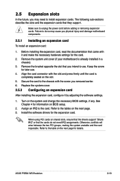
...or that came with the slot and press firmly until the card is already installed in a chassis). 3. Make sure to the tables on BIOS setup. 2. Failure to do not need to install expansion cards. Secure the card to the chassis with the screw you physical injury and ...inoperable. Install the software drivers for information on the next page. 3. Refer to the table on the system and change the necessary BIOS settings, if any. ASUS P5E64 WS Evolution 2-19 2.5 Expansion slots In the future, you intend to use . 4. Before installing the expansion card, read the documentation ...
...or that came with the slot and press firmly until the card is already installed in a chassis). 3. Make sure to the tables on BIOS setup. 2. Failure to do not need to install expansion cards. Secure the card to the chassis with the screw you physical injury and ...inoperable. Install the software drivers for information on the next page. 3. Refer to the table on the system and change the necessary BIOS settings, if any. ASUS P5E64 WS Evolution 2-19 2.5 Expansion slots In the future, you intend to use . 4. Before installing the expansion card, read the documentation ...

Motherboard Installation Guide
Page 49
...then move the jumper again to re-enter data. After the CMOS clearance, reinstall the battery. ® CLRTC P5E64 WS EVOLUTION 12 23 Normal (Default) Clear RTC P5E64 WS Evolution Clear RTC RAM • You do not help, remove the onboard battery and move the cap back to clear... Move the jumper cap from pins 1-2 (default) to overclocking, use the C.P.R. (CPU Parameter Recall) feature. ASUS P5E64 WS Evolution 2-23 Shut down the key during the boot process and enter BIOS setup to clear the CMOS RTC RAM data. Plug the power cord and turn off is required prior using...
...then move the jumper again to re-enter data. After the CMOS clearance, reinstall the battery. ® CLRTC P5E64 WS EVOLUTION 12 23 Normal (Default) Clear RTC P5E64 WS Evolution Clear RTC RAM • You do not help, remove the onboard battery and move the cap back to clear... Move the jumper cap from pins 1-2 (default) to overclocking, use the C.P.R. (CPU Parameter Recall) feature. ASUS P5E64 WS Evolution 2-23 Shut down the key during the boot process and enter BIOS setup to clear the CMOS RTC RAM data. Plug the power cord and turn off is required prior using...
Motherboard Installation Guide
Page 51
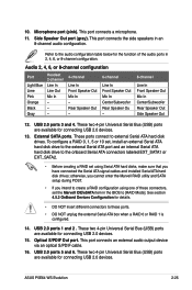
...Bus (USB) ports are available for details. • DO NOT insert different connectors to these connectors, set the Marvell IDE/eSATA item in the BIOS to external Serial ATA hard disk drives. Optical S/PDIF Out port. Rear Speaker Out - 6-channel Line In Front Speaker Out Mic In Center/... Line In Front Speaker Out Mic In Center/Subwoofer Rear Speaker Out Side Speaker Out 12. USB 2.0 ports 3 and 4. This port connects a microphone. 11. ASUS P5E64 WS Evolution 2-25 10. These two 4-pin Universal Serial Bus (USB) ports are available for connecting USB 2.0 devices. 15.
...Bus (USB) ports are available for details. • DO NOT insert different connectors to these connectors, set the Marvell IDE/eSATA item in the BIOS to external Serial ATA hard disk drives. Optical S/PDIF Out port. Rear Speaker Out - 6-channel Line In Front Speaker Out Mic In Center/... Line In Front Speaker Out Mic In Center/Subwoofer Rear Speaker Out Side Speaker Out 12. USB 2.0 ports 3 and 4. This port connects a microphone. 11. ASUS P5E64 WS Evolution 2-25 10. These two 4-pin Universal Serial Bus (USB) ports are available for connecting USB 2.0 devices. 15.
Motherboard Installation Guide
Page 54
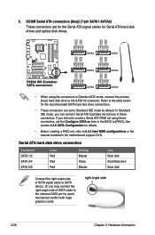
... RSATA_TXP3 GND GND RSATA_RXN4 RSATA_RXP4 GND RSATA_TXN4 RSATA_TXP4 GND GND RSATA_TXP5 RSATA_TXN5 GND RSATA_RXP5 RSATA_RXN5 GND GND RSATA_TXP6 RSATA_TXN6 GND RSATA_RXP6 RSATA_RXN6 GND P5E64 WS EvoPlu5tBioSnATA Connectors SATA connectors SATA6 SATA5 • When using these connectors. If you can connect Serial ATA boot/data hard drives to these... to the SATA1/2 connector. In Standard IDE mode, you intend to create a Serial ATA RAID set using the connectors in the BIOS to SATA device. 3. Or you may connect the right-angle side of SATA signal cable to [RAID].
... RSATA_TXP3 GND GND RSATA_RXN4 RSATA_RXP4 GND RSATA_TXN4 RSATA_TXP4 GND GND RSATA_TXP5 RSATA_TXN5 GND RSATA_RXP5 RSATA_RXN5 GND GND RSATA_TXP6 RSATA_TXN6 GND RSATA_RXP6 RSATA_RXN6 GND P5E64 WS EvoPlu5tBioSnATA Connectors SATA connectors SATA6 SATA5 • When using these connectors. If you can connect Serial ATA boot/data hard drives to these... to the SATA1/2 connector. In Standard IDE mode, you intend to create a Serial ATA RAID set using the connectors in the BIOS to SATA device. 3. Or you may connect the right-angle side of SATA signal cable to [RAID].
Motherboard Installation Guide
Page 55
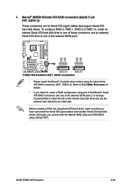
... • Please install the Marvell® Controller driver before using Serial ATA hard disks, make sure that support Serial ATA hard disk drives. ASUS P5E64 WS Evolution 2-29 To configure RAID 0, RAID 1, RAID 5 or RAID 10, install an internal Serial ATA hard disk drive to one of these... ATA RAID connectors [black] (7-pin EXT_SATA1-2) These connectors are for details. • If you cannot enter the Marvell RAID utility and SATA BIOS setup during POST. Refer to 5.2.4 Make Disk menu for Serial ATA signal cables that you have connected the Serial ATA signal cables and installed ...
... • Please install the Marvell® Controller driver before using Serial ATA hard disks, make sure that support Serial ATA hard disk drives. ASUS P5E64 WS Evolution 2-29 To configure RAID 0, RAID 1, RAID 5 or RAID 10, install an internal Serial ATA hard disk drive to one of these... ATA RAID connectors [black] (7-pin EXT_SATA1-2) These connectors are for details. • If you cannot enter the Marvell RAID utility and SATA BIOS setup during POST. Refer to 5.2.4 Make Disk menu for Serial ATA signal cables that you have connected the Serial ATA signal cables and installed ...
Motherboard Installation Guide
Page 59
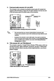
..., digital certificates, passwords, and data. A TPM system also helps enhance network security, protects digital identities, and ensures platform integrity. ® P5E64 WS EVOLUTION TPM P5E64 WS Evolution TPM connector ASUS P5E64 WS Evolution 2-33 AAFP HD Audio-compliant pin definition Legacy AC '97 audio pin definition SENSE2_RETUR SENSE1_RETUR PRESENCE# GND NC NC NC AGND... panel audio I /O module cable to [AC'97]. Front panel audio connector (10-1 pin AAFP) This connector is set the Front Panel Type item in the BIOS setup to this connector, set to [HD Audio]. 11.
..., digital certificates, passwords, and data. A TPM system also helps enhance network security, protects digital identities, and ensures platform integrity. ® P5E64 WS EVOLUTION TPM P5E64 WS Evolution TPM connector ASUS P5E64 WS Evolution 2-33 AAFP HD Audio-compliant pin definition Legacy AC '97 audio pin definition SENSE2_RETUR SENSE1_RETUR PRESENCE# GND NC NC NC AGND... panel audio I /O module cable to [AC'97]. Front panel audio connector (10-1 pin AAFP) This connector is set the Front Panel Type item in the BIOS setup to this connector, set to [HD Audio]. 11.
Motherboard Installation Guide
Page 61
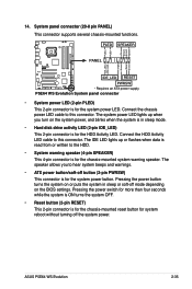
...system power LED lights up or flashes when data is read from or written to this connector. The speaker allows you turn on the BIOS settings. P5E64 WS Evolution System panel connector • System power LED (2-pin PLED) This 2-pin connector is for system reboot without turning off mode ...depending on the system power, and blinks when the system is in sleep or soft-off the system power. ASUS P5E64 WS Evolution 2-35 PWR Ground Reset Ground P5E64 WS EVOLUTION IDE_LED RESET PWRSW * Requires an ATX power supply. Pressing the power switch for more than four seconds while ...
...system power LED lights up or flashes when data is read from or written to this connector. The speaker allows you turn on the BIOS settings. P5E64 WS Evolution System panel connector • System power LED (2-pin PLED) This 2-pin connector is for system reboot without turning off mode ...depending on the system power, and blinks when the system is in sleep or soft-off the system power. ASUS P5E64 WS Evolution 2-35 PWR Ground Reset Ground P5E64 WS EVOLUTION IDE_LED RESET PWRSW * Requires an ATX power supply. Pressing the power switch for more than four seconds while ...
Motherboard Installation Guide
Page 64
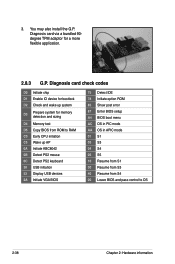
...via a bundled 90degree TPM adaptor for memory detection and sizing D4 Memory test D5 Copy BIOS from ROM to OS 2-38 Chapter 2: Hardware information Diagnosis card check codes D0 Initiate ... keyboard 38 USB initiation 52 Display USB devices 2A Initiate VGA BIOS 75 Detect IDE 78 Initiate option ROM 85 Show post error 87 Enter BIOS setup A4 BIOS boot menu AC OS in PIC mode AA OS in APIC...S1 03 S3 04 S4 05 S5 10 Resume from S1 30 Resume from S3 40 Resume from S4 00 Leave BIOS and pass control to RAM C0 Early CPU initiation C5 Wake up system D3 Prepare system for a more flexible application....
...via a bundled 90degree TPM adaptor for memory detection and sizing D4 Memory test D5 Copy BIOS from ROM to OS 2-38 Chapter 2: Hardware information Diagnosis card check codes D0 Initiate ... keyboard 38 USB initiation 52 Display USB devices 2A Initiate VGA BIOS 75 Detect IDE 78 Initiate option ROM 85 Show post error 87 Enter BIOS setup A4 BIOS boot menu AC OS in PIC mode AA OS in APIC...S1 03 S3 04 S4 05 S5 10 Resume from S1 30 Resume from S3 40 Resume from S4 00 Leave BIOS and pass control to RAM C0 Early CPU initiation C5 Wake up system D3 Prepare system for a more flexible application....
Motherboard Installation Guide
Page 67
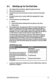
... 4. Check the jumper settings and connections or call your monitor complies with the last device on the screen. ASUS P5E64 WS Evolution 3-1 Connect the power cord to enter the BIOS Setup. External SCSI devices (starting with "green" standards or if it has a "power standby" feature, ... applying power, the system power LED on self tests or POST. Follow the instructions in the following order: a. Monitor b. AMI BIOS beep codes BIOS Beep One short beep One continuous beep followed by two short beeps then a pause (repeated) One continuous beep followed by three short...
... 4. Check the jumper settings and connections or call your monitor complies with the last device on the screen. ASUS P5E64 WS Evolution 3-1 Connect the power cord to enter the BIOS Setup. External SCSI devices (starting with "green" standards or if it has a "power standby" feature, ... applying power, the system power LED on self tests or POST. Follow the instructions in the following order: a. Monitor b. AMI BIOS beep codes BIOS Beep One short beep One continuous beep followed by two short beeps then a pause (repeated) One continuous beep followed by three short...

Motherboard Installation Guide
Page 68
... While the system is ON, pressing the power switch for less than four seconds lets the system enter the soft-off mode regardless of the BIOS setting. Refer to section 4.6 Power Menu in Chapter 4 for more than four seconds puts the system to sleep mode or to shut down the ...® shuts down. If you are using Windows® XP or later version: 1. Click the Turn Off button to soft-off mode, depending on the BIOS setting. Pressing the power switch for details. 3-2 Chapter 3: Powering up 3.2 Turning off the computer 3.2.1 Using the OS shut down function If you are using ...
... While the system is ON, pressing the power switch for less than four seconds lets the system enter the soft-off mode regardless of the BIOS setting. Refer to section 4.6 Power Menu in Chapter 4 for more than four seconds puts the system to sleep mode or to shut down the ...® shuts down. If you are using Windows® XP or later version: 1. Click the Turn Off button to soft-off mode, depending on the BIOS setting. Pressing the power switch for details. 3-2 Chapter 3: Powering up 3.2 Turning off the computer 3.2.1 Using the OS shut down function If you are using ...

Motherboard Installation Guide
Page 69
This chapter tells how to change the Chapter 4: BIOS se4tup system settings through the BIOS Setup menus. Detailed descriptions of the BIOS parameters are also provided.
This chapter tells how to change the Chapter 4: BIOS se4tup system settings through the BIOS Setup menus. Detailed descriptions of the BIOS parameters are also provided.

Motherboard Installation Guide
Page 70
Chapter summary 4 4.1 Managing and updating your BIOS 4-1 4.2 BIOS setup program 4-9 4.3 Main menu 4-12 4.4 Ai Tweaker menu 4-17 4.5 Advanced menu 4-25 4.6 Power menu 4-31 4.7 Boot menu 4-35 4.8 Tools menu 4-39 4.9 Exit menu 4-42 ASUS P5E64 WS Evolution
Chapter summary 4 4.1 Managing and updating your BIOS 4-1 4.2 BIOS setup program 4-9 4.3 Main menu 4-12 4.4 Ai Tweaker menu 4-17 4.5 Advanced menu 4-25 4.6 Power menu 4-31 4.7 Boot menu 4-35 4.8 Tools menu 4-39 4.9 Exit menu 4-42 ASUS P5E64 WS Evolution


