
P5VD2-VM English Edition User's Manual
Page 33
... necessary hardware settings for later use . ASUS P5VD2-MX/P5V-VM DH 1-21 Before installing the expansion card, read the documentation that came with the screw you removed earlier. 6. Make sure to install expansion cards. 1.8 Expansion slots In the future, you may cause you physical injury and damage motherboard components. 1.8.1 Installing an expansion card To...
... necessary hardware settings for later use . ASUS P5VD2-MX/P5V-VM DH 1-21 Before installing the expansion card, read the documentation that came with the screw you removed earlier. 6. Make sure to install expansion cards. 1.8 Expansion slots In the future, you may cause you physical injury and damage motherboard components. 1.8.1 Installing an expansion card To...
P5VD2-VM English Edition User's Manual
Page 35
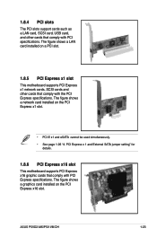
... Express specifications. The figure shows a LAN card installed on a PCI slot. 1.8.5 PCI Express x1 slot This motherboard supports PCI Express x1 network cards, SCSI cards and other cards that comply with PCI specifications. ASUS P5VD2-MX/P5V-VM DH 1-23 1.8.4 PCI slots The PCI slots support cards such as a LAN card, SCSI card, USB card...
... Express specifications. The figure shows a LAN card installed on a PCI slot. 1.8.5 PCI Express x1 slot This motherboard supports PCI Express x1 network cards, SCSI cards and other cards that comply with PCI specifications. ASUS P5VD2-MX/P5V-VM DH 1-23 1.8.4 PCI slots The PCI slots support cards such as a LAN card, SCSI card, USB card...
P5VD2-VM English Edition User's Manual
Page 37
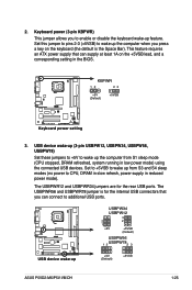
... power mode). The USBPWR56 and USBPWR78 jumper is the Space Bar). KBPWR 12 23 +5V (Default) +5VSB ® Keyboard power setting 3. This feature requires an ATX power supply that you to CPU, DRAM in slow refresh, power supply in the BIOS. USBPW34 USBPW12 3 2 2 1 +5V +5VSB (Default) ® USBPW56 1 2 USBPW782 3 USB device... +5V to additional USB ports. The USBPWR12 and USBPWR34 jumpers are for the internal USB connectors that can connect to wake up +5V (Default) +5VSB ASUS P5VD2-MX/P5V-VM DH 1-25
... power mode). The USBPWR56 and USBPWR78 jumper is the Space Bar). KBPWR 12 23 +5V (Default) +5VSB ® Keyboard power setting 3. This feature requires an ATX power supply that you to CPU, DRAM in slow refresh, power supply in the BIOS. USBPW34 USBPW12 3 2 2 1 +5V +5VSB (Default) ® USBPW56 1 2 USBPW782 3 USB device... +5V to additional USB ports. The USBPWR12 and USBPWR34 jumpers are for the internal USB connectors that can connect to wake up +5V (Default) +5VSB ASUS P5VD2-MX/P5V-VM DH 1-25
P5VD2-VM English Edition User's Manual
Page 39
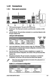
.... 6. Audio 2, 4, or 6-channel configuration Port Light Blue Lime Pink Headset 2-channel Line In Headphone/Front Microphone 4-channel Surround Front Microphone 6-channel Surround Front Center/Subwoofer ASUS P5VD2-MX/P5V-VM DH 1-27 LAN (RJ-45) port. This port connects a microphone. In 4channel and 6-channel configuration, the function of this port becomes Bass/Center Speaker...
.... 6. Audio 2, 4, or 6-channel configuration Port Light Blue Lime Pink Headset 2-channel Line In Headphone/Front Microphone 4-channel Surround Front Microphone 6-channel Surround Front Center/Subwoofer ASUS P5VD2-MX/P5V-VM DH 1-27 LAN (RJ-45) port. This port connects a microphone. In 4channel and 6-channel configuration, the function of this port becomes Bass/Center Speaker...
P5VD2-VM English Edition User's Manual
Page 41
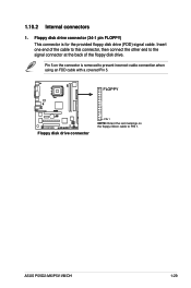
Insert one end of the cable to this connector, then connect the other end to prevent incorrect cable connection when using an FDD cable with a covered Pin 5. Pin 5 on the floppy ribbon cable to PIN 1. FLOPPY ® Floppy disk drive connector PIN 1 NOTE: Orient the red markings on the connector is for the provided floppy disk drive (FDD) signal cable. ASUS P5VD2-MX/P5V-VM DH 1-29 1.10.2 Internal connectors 1. Floppy disk drive connector (34-1 pin FLOPPY) This connector is removed to the signal connector at the back of the floppy disk drive.
Insert one end of the cable to this connector, then connect the other end to prevent incorrect cable connection when using an FDD cable with a covered Pin 5. Pin 5 on the floppy ribbon cable to PIN 1. FLOPPY ® Floppy disk drive connector PIN 1 NOTE: Orient the red markings on the connector is for the provided floppy disk drive (FDD) signal cable. ASUS P5VD2-MX/P5V-VM DH 1-29 1.10.2 Internal connectors 1. Floppy disk drive connector (34-1 pin FLOPPY) This connector is removed to the signal connector at the back of the floppy disk drive.


