User Manual
Page 7
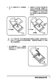
5. 從 CPU PnP 6. 請確認 CPU CPU CPU PnP 保護蓋 CPU CPU CPU CPU 7 A B A B
5. 從 CPU PnP 6. 請確認 CPU CPU CPU PnP 保護蓋 CPU CPU CPU CPU 7 A B A B
User Manual
Page 3
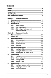
... this guide x P5QC specifications summary xii Chapter 1: Product introduction 1.1 Welcome 1-1 1.2 Package contents 1-1 1.3 Special features 1-2 1.3.1 Product highlights 1-2 1.3.2 ASUS unique features 1-3 1.3.3 ASUS Intelligent Performance and Overclocking features 1-7 Chapter 2: Hardware information 2.1 Before you proceed 2-1 Onboard LED 2-1 2.2 Motherboard overview 2-2 2.2.1 Motherboard layout 2-2 2.2.2 Layout contents 2-3 2.2.3 Placement direction 2-4 2.2.4 Screw holes 2-4 2.3 Central Processing Unit (CPU 2-5 2.3.1 Installing the CPU 2-6 2.3.2 Installing the CPU heatsink and...
... this guide x P5QC specifications summary xii Chapter 1: Product introduction 1.1 Welcome 1-1 1.2 Package contents 1-1 1.3 Special features 1-2 1.3.1 Product highlights 1-2 1.3.2 ASUS unique features 1-3 1.3.3 ASUS Intelligent Performance and Overclocking features 1-7 Chapter 2: Hardware information 2.1 Before you proceed 2-1 Onboard LED 2-1 2.2 Motherboard overview 2-2 2.2.1 Motherboard layout 2-2 2.2.2 Layout contents 2-3 2.2.3 Placement direction 2-4 2.2.4 Screw holes 2-4 2.3 Central Processing Unit (CPU 2-5 2.3.1 Installing the CPU 2-6 2.3.2 Installing the CPU heatsink and...
User Manual
Page 7
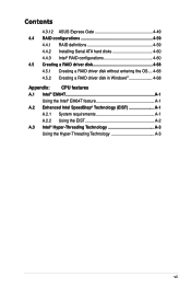
Contents 4.3.12 ASUS Express Gate 4-49 4.4 RAID configurations 4-59 4.4.1 RAID definitions 4-59 4.4.2 Installing Serial ATA hard disks 4-60 4.4.3 Intel® RAID configurations 4-60 4.5 Creating a RAID driver disk 4-68 4.5.1 Creating a RAID driver disk without entering the OS.... 4-68 4.5.2 Creating a RAID driver disk in Windows 4-68 Appendix: CPU features A.1 Intel® EM64T A-1 Using the Intel...
Contents 4.3.12 ASUS Express Gate 4-49 4.4 RAID configurations 4-59 4.4.1 RAID definitions 4-59 4.4.2 Installing Serial ATA hard disks 4-60 4.4.3 Intel® RAID configurations 4-60 4.5 Creating a RAID driver disk 4-68 4.5.1 Creating a RAID driver disk without entering the OS.... 4-68 4.5.2 Creating a RAID driver disk in Windows 4-68 Appendix: CPU features A.1 Intel® EM64T A-1 Using the Intel...
User Manual
Page 10
... of the BIOS parameters are not part of the support DVD that comes with the motherboard package and the software. • Appendix: CPU features The Appendix describes the CPU features and technologies that the motherboard supports. ASUS websites The ASUS website provides updated information on the motherboard. • Chapter 3: BIOS setup This chapter tells how to the...
... of the BIOS parameters are not part of the support DVD that comes with the motherboard package and the software. • Appendix: CPU features The Appendix describes the CPU features and technologies that the motherboard supports. ASUS websites The ASUS website provides updated information on the motherboard. • Chapter 3: BIOS setup This chapter tells how to the...
User Manual
Page 12
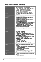
... PCIe 2.0 x16 slot supports PCIe 2.0 mode 3 x PCIe x1 slots 2 x PCI slots Intel® ICH10R Southbridge: - 6 x SATA 3.0 Gb/s ports - ASUS Noise-Filtering LSI® L-FW3227 1394a controller supports 2 x IEEE 1394a ports (one at mid-board, one at back panel) 12 x USB 2.0 ports (6 ports at... mid-board, 6 ports at back I/O - Supports Jack-Detecting, Multi-streaming, and Front Panel Jack-Retasking - P5QC specifications summary CPU Chipset System Bus Memory Expansion Slots Storage LAN Audio IEEE 1394 USB LGA775 socket for Intel® Core™2 Extreme / Core™2 ...
... PCIe 2.0 x16 slot supports PCIe 2.0 mode 3 x PCIe x1 slots 2 x PCI slots Intel® ICH10R Southbridge: - 6 x SATA 3.0 Gb/s ports - ASUS Noise-Filtering LSI® L-FW3227 1394a controller supports 2 x IEEE 1394a ports (one at mid-board, one at back panel) 12 x USB 2.0 ports (6 ports at... mid-board, 6 ports at back I/O - Supports Jack-Detecting, Multi-streaming, and Front Panel Jack-Retasking - P5QC specifications summary CPU Chipset System Bus Memory Expansion Slots Storage LAN Audio IEEE 1394 USB LGA775 socket for Intel® Core™2 Extreme / Core™2 ...

User Manual
Page 13
... (N.B.): 40-step chipset voltage control - ASUS AI Direct Link ASUS Quiet Thermal Solution: - ASUS Drive Xpert - ASUS Q-Shield - ASUS CrashFree BIOS 3 - ASUS EPU-6 Engine - Profile - vCore: Adjustable CPU voltage at 1MHz increment - vFSB Termination: 15-step Hyper Transport voltage control SFS (Stepless Frequency Selection) - P5QC specifications summary ASUS Unique features ASUS Exclusive Overclocking Features ASUS Power Saving Solution: - vCPU PLL: 64...
... (N.B.): 40-step chipset voltage control - ASUS AI Direct Link ASUS Quiet Thermal Solution: - ASUS Drive Xpert - ASUS Q-Shield - ASUS CrashFree BIOS 3 - ASUS EPU-6 Engine - Profile - vCore: Adjustable CPU voltage at 1MHz increment - vFSB Termination: 15-step Hyper Transport voltage control SFS (Stepless Frequency Selection) - P5QC specifications summary ASUS Unique features ASUS Exclusive Overclocking Features ASUS Power Saving Solution: - vCPU PLL: 64...
User Manual
Page 14
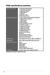
...P5QC specifications summary Back Panel I/O Ports 1 x PS/2 keyboard port (Purple) 1 x PS/2 mouse port (Green) 1 x S/PDIF Out (Coaxial) 1 x IEEE1394a port 1 x RJ45 port 6 x USB 2.0/1.1 ports 8-channel Audio I/O ports Internal I/O Connectors 3 x USB connectors support additional 6 USB ports 1 x Floppy disk drive connector 1 x COM connector 1 x IDE connector 6 x SATA connectors 2 x Drive Xpert SATA connectors 1 x CPU..., PXE, Support DVD Contents Drivers ASUS PC Probe II ASUS Update ASUS AI Suite Image-Editing Suite Anti-virus software (OEM version) Form Factor ATX Form Factor, 12"x 9.6" (30...
...P5QC specifications summary Back Panel I/O Ports 1 x PS/2 keyboard port (Purple) 1 x PS/2 mouse port (Green) 1 x S/PDIF Out (Coaxial) 1 x IEEE1394a port 1 x RJ45 port 6 x USB 2.0/1.1 ports 8-channel Audio I/O ports Internal I/O Connectors 3 x USB connectors support additional 6 USB ports 1 x Floppy disk drive connector 1 x COM connector 1 x IDE connector 6 x SATA connectors 2 x Drive Xpert SATA connectors 1 x CPU..., PXE, Support DVD Contents Drivers ASUS PC Probe II ASUS Update ASUS AI Suite Image-Editing Suite Anti-virus software (OEM version) Form Factor ATX Form Factor, 12"x 9.6" (30...

User Manual
Page 20
... Ferrite core chokes with lower hysteresis loss, and high quality Japanese-made conductive polymer capacitors all add up to operating temperatures, ASUS' 3rd generation 8-phase VRM design leads the industry with its 95% power efficiency. and optimizes the energy providing system in... and is the world's first energy-saving solution that can adjust both CPU and VGA voltages. ASUS 3rd Generation 8 Phase Power Design Longer Life, & Higher Efficiency! ASUS Power Saving Solution ASUS Power Saving solution intelligently and automatically provides balanced computing power and energy consumption...
... Ferrite core chokes with lower hysteresis loss, and high quality Japanese-made conductive polymer capacitors all add up to operating temperatures, ASUS' 3rd generation 8-phase VRM design leads the industry with its 95% power efficiency. and optimizes the energy providing system in... and is the world's first energy-saving solution that can adjust both CPU and VGA voltages. ASUS 3rd Generation 8 Phase Power Design Longer Life, & Higher Efficiency! ASUS Power Saving Solution ASUS Power Saving solution intelligently and automatically provides balanced computing power and energy consumption...
User Manual
Page 21
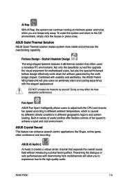
...Skype, online game, video conference and recording. Fanless Design - Not only the beautifully curved fins upgrade the visual enjoyment for motherboard users, but also the special thickened bottom design effectively cools down hot airflows generated by yourself. Doing so may affect the heat...the overall sound field without introducing a picket fencing effect. Fan Xpert ASUS Fan Xpert intelligently allows users to adjust both the CPU and chassis fan speed according to achieve a quiet and cool environment. ASUS P5QC 1-5 Combined with the elegant appearance! Built-in variety of useful ...
...Skype, online game, video conference and recording. Fanless Design - Not only the beautifully curved fins upgrade the visual enjoyment for motherboard users, but also the special thickened bottom design effectively cools down hot airflows generated by yourself. Doing so may affect the heat...the overall sound field without introducing a picket fencing effect. Fan Xpert ASUS Fan Xpert intelligently allows users to adjust both the CPU and chassis fan speed according to achieve a quiet and cool environment. ASUS P5QC 1-5 Combined with the elegant appearance! Built-in variety of useful ...
User Manual
Page 23
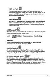
... multiple BIOS settings. Profile that allows users to overclocking, C.P.R. feature of booting the BIOS. ASUS P5QC 1-7 Update your screen. 1.3.3 ASUS Intelligent Performance and Overclocking features AI Booster The ASUS AI Booster allows you to achieve the most precise setting for each parameter. eliminates the need to overclocking. C.P.R. (CPU Parameter Recall) The C.P.R. ASUS O.C. Profile The motherboard features the...
... multiple BIOS settings. Profile that allows users to overclocking, C.P.R. feature of booting the BIOS. ASUS P5QC 1-7 Update your screen. 1.3.3 ASUS Intelligent Performance and Overclocking features AI Booster The ASUS AI Booster allows you to achieve the most precise setting for each parameter. eliminates the need to overclocking. C.P.R. (CPU Parameter Recall) The C.P.R. ASUS O.C. Profile The motherboard features the...
User Manual
Page 26
Chapter summary 2 2.1 Before you proceed 2-1 2.2 Motherboard overview 2-2 2.3 Central Processing Unit (CPU 2-5 2.4 System memory 2-11 2.5 Expansion slots 2-18 2.6 Jumpers 2-21 2.7 Connectors 2-24 2.8 Starting up for the first time 2-39 2.9 Turning off the computer 2-40 ASUS P5QC
Chapter summary 2 2.1 Before you proceed 2-1 2.2 Motherboard overview 2-2 2.3 Central Processing Unit (CPU 2-5 2.4 System memory 2-11 2.5 Expansion slots 2-18 2.6 Jumpers 2-21 2.7 Connectors 2-24 2.8 Starting up for the first time 2-39 2.9 Turning off the computer 2-40 ASUS P5QC
User Manual
Page 29
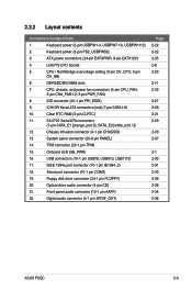
...TPM) 15. Onboard LED (SB_PWR) 16. SATA_E2 [white, port 1]) 12. IDE connector (40-1 pin PRI_EIDE) 9. ATX power connectors (24-pin EATXPWR, 8-pin EATX12V) 4. CPU, chassis, and power fan connectors (4-pin CPU_FAN; 3-pin CHA_FAN1-2; 3-pin PWR_FAN) 8. Chassis intrusion connector (4-1 pin CHASSIS)... 2-35 2-6 2-23 2-11 2-32 2-27 2-28 2-21 2-29 2-33 2-37 2-1 2-30 2-31 2-33 2-26 2-36 2-34 2-36 ASUS P5QC 2-3 ICH10R Serial ATA connectors [red] (7-pin SATA1-6) 10. Floppy disk drive connector (34-1 pin FLOPPY) 20. 2.2.2 Layout contents Connectors/Jumpers/Slots ...
...TPM) 15. Onboard LED (SB_PWR) 16. SATA_E2 [white, port 1]) 12. IDE connector (40-1 pin PRI_EIDE) 9. ATX power connectors (24-pin EATXPWR, 8-pin EATX12V) 4. CPU, chassis, and power fan connectors (4-pin CPU_FAN; 3-pin CHA_FAN1-2; 3-pin PWR_FAN) 8. Chassis intrusion connector (4-1 pin CHASSIS)... 2-35 2-6 2-23 2-11 2-32 2-27 2-28 2-21 2-29 2-33 2-37 2-1 2-30 2-31 2-33 2-26 2-36 2-34 2-36 ASUS P5QC 2-3 ICH10R Serial ATA connectors [red] (7-pin SATA1-6) 10. Floppy disk drive connector (34-1 pin FLOPPY) 20. 2.2.2 Layout contents Connectors/Jumpers/Slots ...
User Manual
Page 31
...ASUS P5QC 2-5 ASUS will shoulder the cost of the PnP cap. Contact your retailer immediately if the PnP cap is missing, or if you use FSB 800MHz CPU or above. • Upon purchase of the motherboard, make sure that all power cables are not bent. 2.3 Central Processing Unit (CPU) The motherboard...contacts resulting from incorrect CPU installation/removal, or misplacement/loss/ incorrect removal of repair only if the damage is on the LGA775 socket. • The product warranty does not cover damage to the PnP cap/socket contacts/motherboard components. ASUS will process Return ...
...ASUS P5QC 2-5 ASUS will shoulder the cost of the PnP cap. Contact your retailer immediately if the PnP cap is missing, or if you use FSB 800MHz CPU or above. • Upon purchase of the motherboard, make sure that all power cables are not bent. 2.3 Central Processing Unit (CPU) The motherboard...contacts resulting from incorrect CPU installation/removal, or misplacement/loss/ incorrect removal of repair only if the damage is on the LGA775 socket. • The product warranty does not cover damage to the PnP cap/socket contacts/motherboard components. ASUS will process Return ...
User Manual
Page 32
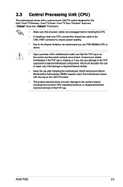
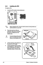
... sure that the cam box is facing towards you are installing a CPU. Retention tab A B Load lever 3. Locate the CPU socket on your left (B) until it is on the motherboard. To prevent damage to the socket pins, do not remove the PnP cap unless you and the load lever is released from the 4B... (4B). 3 PnP cap Load plate 4A 2-6 Chapter 2: Hardware information Press the load lever with your thumb (A), then move it to a 135º angle. 4. 2.3.1 Installing the CPU To install...
... sure that the cam box is facing towards you are installing a CPU. Retention tab A B Load lever 3. Locate the CPU socket on your left (B) until it is on the motherboard. To prevent damage to the socket pins, do not remove the PnP cap unless you and the load lever is released from the 4B... (4B). 3 PnP cap Load plate 4A 2-6 Chapter 2: Hardware information Press the load lever with your thumb (A), then move it to a 135º angle. 4. 2.3.1 Installing the CPU To install...

User Manual
Page 33
...is spread in only one correct orientation. CPU notch Alignment key 6. If it off immediately, and seek professional medical help. ASUS P5QC 2-7 5. DO NOT force the CPU into the CPU notch. Apply several drops of thermal paste to the exposed area of the CPU that the heatsink will be in contact ... is toxic and inedible. Some heatsinks come with your skin, ensure to prevent bending the connectors on the socket and damaging the CPU! To prevent contaminating the paste, DO NOT spread the paste with preapplied thermal paste. Gold triangle mark The Thermal Interface Material is...
...is spread in only one correct orientation. CPU notch Alignment key 6. If it off immediately, and seek professional medical help. ASUS P5QC 2-7 5. DO NOT force the CPU into the CPU notch. Apply several drops of thermal paste to the exposed area of the CPU that the heatsink will be in contact ... is toxic and inedible. Some heatsinks come with your skin, ensure to prevent bending the connectors on the socket and damaging the CPU! To prevent contaminating the paste, DO NOT spread the paste with preapplied thermal paste. Gold triangle mark The Thermal Interface Material is...

User Manual
Page 34
B The motherboard supports Intel® LGA775 processors with the Intel® Enhanced Memory 64 Technology (EM64T), Enhanced Intel SpeedStep® Technology (EIST), and Hyper-Threading Technology. 7. Refer to the Appendix for more information on these CPU features. 2-8 Chapter 2: Hardware information Close the load plate (A), then push the load lever (B) until it snaps into A the retention tab.
B The motherboard supports Intel® LGA775 processors with the Intel® Enhanced Memory 64 Technology (EM64T), Enhanced Intel SpeedStep® Technology (EIST), and Hyper-Threading Technology. 7. Refer to the Appendix for more information on these CPU features. 2-8 Chapter 2: Hardware information Close the load plate (A), then push the load lever (B) until it snaps into A the retention tab.
User Manual
Page 35
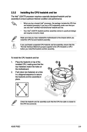
...installed CPU, making sure that you have installed the motherboard to the chassis before you purchased a separate CPU heatsink and fan assembly, ensure that the CPU fan cable is closest to the CPU heatsink or CPU before you buy a CPU separately..., make sure that you use only Intel®‑certified multi‑directional heatsink and fan. • Your Intel® LGA775 heatsink and fan assembly comes in place. ASUS P5QC 2-9 Place the heatsink on the motherboard. To install the CPU...
...installed CPU, making sure that you have installed the motherboard to the chassis before you purchased a separate CPU heatsink and fan assembly, ensure that the CPU fan cable is closest to the CPU heatsink or CPU before you buy a CPU separately..., make sure that you use only Intel®‑certified multi‑directional heatsink and fan. • Your Intel® LGA775 heatsink and fan assembly comes in place. ASUS P5QC 2-9 Place the heatsink on the motherboard. To install the CPU...

User Manual
Page 36
Rotate each fastener counterclockwise. Connect the CPU fan cable to disengage the heatsink and fan assembly from the motherboard. A B A A B B A 4. B 3. Carefully remove the heatsink and fan assembly from the connector on the motherboard labeled CPU_FAN. Disconnect the CPU fan cable from the motherboard. 2-10 Chapter 2: Hardware information Pull up two fasteners at a time in a diagonal sequence to...
Rotate each fastener counterclockwise. Connect the CPU fan cable to disengage the heatsink and fan assembly from the motherboard. A B A A B B A 4. B 3. Carefully remove the heatsink and fan assembly from the connector on the motherboard labeled CPU_FAN. Disconnect the CPU fan cable from the motherboard. 2-10 Chapter 2: Hardware information Pull up two fasteners at a time in a diagonal sequence to...
User Manual
Page 47
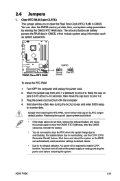
... cause system boot failure! • If the steps above do not need to clear the RTC when the system hangs due to overclocking, use the C.P.R. (CPU Parameter Recall) feature. ASUS P5QC 2-21
... cause system boot failure! • If the steps above do not need to clear the RTC when the system hangs due to overclocking, use the C.P.R. (CPU Parameter Recall) feature. ASUS P5QC 2-21
User Manual
Page 48
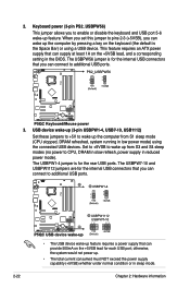
This feature requires an ATX power supply that you can supply at least 1A on the keyboard (the default is the Space Bar)...5VSB lead for the internal USB connectors that can wake up feature. Keyboard power (3-pin PS2_USBPW56) This jumper allows you can connect to CPU, DRAM in slow refresh, power supply in the BIOS. USB device wake-up (3-pin USBPW1-4, USB7-10, USB1112) Set these ...When you set this jumper to pins 2-3 (+5VSB), you can connect to wake up from S1 sleep mode (CPU stopped, DRAM refreshed, system running in sleep mode. 2-22 Chapter 2: Hardware information
This feature requires an ATX power supply that you can supply at least 1A on the keyboard (the default is the Space Bar)...5VSB lead for the internal USB connectors that can wake up feature. Keyboard power (3-pin PS2_USBPW56) This jumper allows you can connect to CPU, DRAM in slow refresh, power supply in the BIOS. USB device wake-up (3-pin USBPW1-4, USB7-10, USB1112) Set these ...When you set this jumper to pins 2-3 (+5VSB), you can connect to wake up from S1 sleep mode (CPU stopped, DRAM refreshed, system running in sleep mode. 2-22 Chapter 2: Hardware information


