
Motherboard Installation Guide
Page 4
Contents 1.9 1.10 Jumpers 1-21 Connectors 1-23 1.10.1 Rear panel connectors 1-23 1.10.2 Internal connectors 1-24 Chapter 2: BIOS setup 2.1 Managing and updating your BIOS 2-2 2.1.1 Creating a bootable floppy disk 2-2 2.1.2 ASUS EZ Flash utility 2-3 2.1.3 AFUDOS utility 2-4 2.1.4 ASUS Update utility 2-6 2.2 BIOS setup program 2-9 2.2.1 BIOS menu screen 2-10 2.2.2 Menu bar 2-10 2.2.3 Navigation keys 2-10 2.2.4 Menu items 2-11 2.2.5 Sub-menu...
Contents 1.9 1.10 Jumpers 1-21 Connectors 1-23 1.10.1 Rear panel connectors 1-23 1.10.2 Internal connectors 1-24 Chapter 2: BIOS setup 2.1 Managing and updating your BIOS 2-2 2.1.1 Creating a bootable floppy disk 2-2 2.1.2 ASUS EZ Flash utility 2-3 2.1.3 AFUDOS utility 2-4 2.1.4 ASUS Update utility 2-6 2.2 BIOS setup program 2-9 2.2.1 BIOS menu screen 2-10 2.2.2 Menu bar 2-10 2.2.3 Navigation keys 2-10 2.2.4 Menu items 2-11 2.2.5 Sub-menu...

Motherboard Installation Guide
Page 11
... 2 x USB 2.0 connectors for 4 additional USB 2.0 ports 1 x CPU fan connector 1 x Chassis fan connector 1 x 20-pin ATX power connector 1 x 4-pin ATX 12 V power connector 1 x CD connector 1 x Front panel audio connector 1 x 10-pin Panel connector 1 x Speaker connector ATX power supply (with 20-pin and 4-pin 12 V plugs) Micro-ATX form factor: 9.6 in x 7.6 in Device drivers...
... 2 x USB 2.0 connectors for 4 additional USB 2.0 ports 1 x CPU fan connector 1 x Chassis fan connector 1 x 20-pin ATX power connector 1 x 4-pin ATX 12 V power connector 1 x CD connector 1 x Front panel audio connector 1 x 10-pin Panel connector 1 x Speaker connector ATX power supply (with 20-pin and 4-pin 12 V plugs) Micro-ATX form factor: 9.6 in x 7.6 in Device drivers...

Motherboard Installation Guide
Page 35
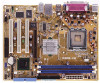
This port is for the LAN port LED indications. LAN (RJ-45) port. Line In port (light blue). Microphone port (pink). ASUS P5PE-VM 1-23 Refer to a Local Area Network (LAN) through a network hub. This 25-pin port connects a parallel printer, a scanner, or other audio sources. Line ... port connects a tape, CD, DVD player, or other devices. 3. In a 6‑channel configuration, the function of this port becomes Bass/center. 5. 1.10 Connectors 1.10.1 Rear panel connectors 1 2 3 4 5 6 11 10 9 8 7 1.
This port is for the LAN port LED indications. LAN (RJ-45) port. Line In port (light blue). Microphone port (pink). ASUS P5PE-VM 1-23 Refer to a Local Area Network (LAN) through a network hub. This 25-pin port connects a parallel printer, a scanner, or other audio sources. Line ... port connects a tape, CD, DVD player, or other devices. 3. In a 6‑channel configuration, the function of this port becomes Bass/center. 5. 1.10 Connectors 1.10.1 Rear panel connectors 1 2 3 4 5 6 11 10 9 8 7 1.

Motherboard Installation Guide
Page 39
... this connector. P5PE-VM AGND PRESENSE# MIC2_JD HP_HD MIC2_L MIC2_R HP_R Jack_Sense HP_L R FP_AUDIO P5PE-VM Front Panel Audio Connector ASUS P5PE-VM 1-27 5. Front panel audio connector (10-1 pin FP_AUDIO) This connector is for a chassis-mounted front panel audio I /O module cable to hear system beeps and warnings. Connect one end of the front...
... this connector. P5PE-VM AGND PRESENSE# MIC2_JD HP_HD MIC2_L MIC2_R HP_R Jack_Sense HP_L R FP_AUDIO P5PE-VM Front Panel Audio Connector ASUS P5PE-VM 1-27 5. Front panel audio connector (10-1 pin FP_AUDIO) This connector is for a chassis-mounted front panel audio I /O module cable to hear system beeps and warnings. Connect one end of the front...
Motherboard Installation Guide
Page 42
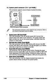
System panel connector (10-1 pin PANEL) This connector supports several chassis-mounted functions. Refer to this connector. The system power LED lights up or flashes when data is for the HDD ... on the system power, and blinks when the system is color-coded for the system power LED. Ground Reset P5PE-VM System Panel Connector HDLED RESET The sytem panel connector is in SLEEP or SOFT-OFF mode depending on the BIOS settings. Connect the HDD Activity LED cable to the HDD. •...
System panel connector (10-1 pin PANEL) This connector supports several chassis-mounted functions. Refer to this connector. The system power LED lights up or flashes when data is for the HDD ... on the system power, and blinks when the system is color-coded for the system power LED. Ground Reset P5PE-VM System Panel Connector HDLED RESET The sytem panel connector is in SLEEP or SOFT-OFF mode depending on the BIOS settings. Connect the HDD Activity LED cable to the HDD. •...


