P5P800 User's manual English Edition E1906
Page 3
... this guide is organized ix Where to find more information ix Conventions used in this guide x Typography x P5P800 specifications summary xi Chapter 1: Product introduction 1.1 Welcome 1-1 1.2 Package contents 1-1 1.3 Special features 1-2 1.3.1 Product highlights 1-2 1.3.2 ASUS Proactive feature 1-3 1.3.3 Innovative ASUS features 1-4 Chapter 2: Hardware information 2.1 Before you proceed 2-1 2.2 Motherboard overview 2-2 2.2.1 Placement direction 2-2 2.2.2 Screw holes 2-2 2.2.3 Motherboard layout 2-3 2.2.4 Layout Contents...
... this guide is organized ix Where to find more information ix Conventions used in this guide x Typography x P5P800 specifications summary xi Chapter 1: Product introduction 1.1 Welcome 1-1 1.2 Package contents 1-1 1.3 Special features 1-2 1.3.1 Product highlights 1-2 1.3.2 ASUS Proactive feature 1-3 1.3.3 Innovative ASUS features 1-4 Chapter 2: Hardware information 2.1 Before you proceed 2-1 2.2 Motherboard overview 2-2 2.2.1 Placement direction 2-2 2.2.2 Screw holes 2-2 2.2.3 Motherboard layout 2-3 2.2.4 Layout Contents...

P5P800 User's manual English Edition E1906
Page 5
...Fourth IDE Master 4-14 4.3.6 IDE Configuration 4-15 4.3.7 System Information 4-17 4.4 Advanced menu 4-18 4.4.1 JumperFree Configuration 4-18 4.4.2 CPU Configuration 4-21 4.4.3 Chipset 4-22 4.4.4 Onboard Devices Configuration 4-24 4.4.5 PCI PnP 4-26 4.4.6 USB Configuration 4-27 4.4.7 Instant Music... an operating system 5-1 5.2 Support CD information 5-1 5.2.1 Running the support CD 5-1 5.2.2 Drivers menu 5-2 5.2.3 Utilities menu 5-3 5.2.4 ASUS Contact information 5-4 5.2.5 Other information 5-5 5.3 Software information 5-7 v Contents 4.3.5 Primary and Secondary Master/Slave;
...Fourth IDE Master 4-14 4.3.6 IDE Configuration 4-15 4.3.7 System Information 4-17 4.4 Advanced menu 4-18 4.4.1 JumperFree Configuration 4-18 4.4.2 CPU Configuration 4-21 4.4.3 Chipset 4-22 4.4.4 Onboard Devices Configuration 4-24 4.4.5 PCI PnP 4-26 4.4.6 USB Configuration 4-27 4.4.7 Instant Music... an operating system 5-1 5.2 Support CD information 5-1 5.2.1 Running the support CD 5-1 5.2.2 Drivers menu 5-2 5.2.3 Utilities menu 5-3 5.2.4 ASUS Contact information 5-4 5.2.5 Other information 5-5 5.3 Software information 5-7 v Contents 4.3.5 Primary and Secondary Master/Slave;
P5P800 User's manual English Edition E1906
Page 11
... Cable Tester technology Supports POST Network-diagnostic program ASUS AI NOS™ (Non-delay Overclocking System) feature ASUS AI Overclocking (Intelligent CPU frequency tuner) ASUS C.P.R. (CPU Parameter Recall) CPU, Memory, and AGP voltage adjustable Stepless Frequency ...Selection(SFS) from 100 MHz up to 400 MHz at 1 MHz increment Adjustable FSB/DDR ratio with 5.1-channel CODEC SoundBlaster® Live! P5P800 specifications summary CPU...
... Cable Tester technology Supports POST Network-diagnostic program ASUS AI NOS™ (Non-delay Overclocking System) feature ASUS AI Overclocking (Intelligent CPU frequency tuner) ASUS C.P.R. (CPU Parameter Recall) CPU, Memory, and AGP voltage adjustable Stepless Frequency ...Selection(SFS) from 100 MHz up to 400 MHz at 1 MHz increment Adjustable FSB/DDR ratio with 5.1-channel CODEC SoundBlaster® Live! P5P800 specifications summary CPU...

P5P800 User's manual English Edition E1906
Page 12
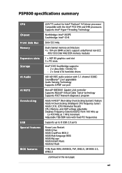
P5P800 specifications summary Rear panel Internal connectors Power Requirement Form Factor Support CD contents 1 x Parallel port 1 x Serial port 1 x LAN (RJ-45) port 4 x USB 2.0 ports 1 x S/PDIF out port 1 x PS/2 keyboard port 1 x PS/2 mouse port 6-channel audio ports 1 x Floppy disk drive connector 2 x IDE connectors 2 x Serial ATA connectors 1 x CPU fan ...12 V plugs) ATX 12 V 2.0 compliant ATX form factor: 12 in x 9.6 in (30.5 cm x 24.4 cm) Device drivers ASUS PC Probe ASUS Live Update Utility Anti-virus software (OEM version) *Specifications are subject to change without notice. xii
P5P800 specifications summary Rear panel Internal connectors Power Requirement Form Factor Support CD contents 1 x Parallel port 1 x Serial port 1 x LAN (RJ-45) port 4 x USB 2.0 ports 1 x S/PDIF out port 1 x PS/2 keyboard port 1 x PS/2 mouse port 6-channel audio ports 1 x Floppy disk drive connector 2 x IDE connectors 2 x Serial ATA connectors 1 x CPU fan ...12 V plugs) ATX 12 V 2.0 compliant ATX form factor: 12 in x 9.6 in (30.5 cm x 24.4 cm) Device drivers ASUS PC Probe ASUS Live Update Utility Anti-virus software (OEM version) *Specifications are subject to change without notice. xii
P5P800 User's manual English Edition E1906
Page 17
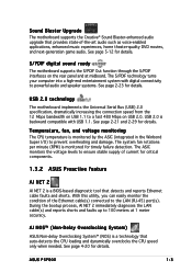
...CPU temperature is monitored by the ASIC (integrated in the Winbond Super I/O) to ensure stable supply of current for critical components. 1.3.2 ASUS Proactive feature AI NET 2 AI NET 2 is monitored for timely failure detection. The ASIC monitors the voltage levels to prevent overheating and damage. See page 4-20 for details. ASUS P5P800... 1-3 The S/PDIF technology turns your computer into a high-end entertainment system with USB 1.1. AI NOS™ (Non-Delay Overclocking System) ASUS Non-delay Overclocking System™ (NOS...
...CPU temperature is monitored by the ASIC (integrated in the Winbond Super I/O) to ensure stable supply of current for critical components. 1.3.2 ASUS Proactive feature AI NET 2 AI NET 2 is monitored for timely failure detection. The ASIC monitors the voltage levels to prevent overheating and damage. See page 4-20 for details. ASUS P5P800... 1-3 The S/PDIF technology turns your computer into a high-end entertainment system with USB 1.1. AI NOS™ (Non-Delay Overclocking System) ASUS Non-delay Overclocking System™ (NOS...

P5P800 User's manual English Edition E1906
Page 18
...Chapter 1: Product introduction Simply shut down and reboot the system, and the BIOS automatically restores the CPU previous setting for details. See page 4-13 for details. ASUS Instant Music This unique feature allows you to open the system chassis and clear the RTC data...eliminates the need to overclocking, C.P.R. 1.3.3 Innovative ASUS features CPU Lock Free support The motherboard supports the CPU Lock Free feature that allows you to adjust the CPU multiplier to ensure quiet, cool, and efficient operation. CPU Lock Free boosts overall performance by making synchronous ...
...Chapter 1: Product introduction Simply shut down and reboot the system, and the BIOS automatically restores the CPU previous setting for details. See page 4-13 for details. ASUS Instant Music This unique feature allows you to open the system chassis and clear the RTC data...eliminates the need to overclocking, C.P.R. 1.3.3 Innovative ASUS features CPU Lock Free support The motherboard supports the CPU Lock Free feature that allows you to adjust the CPU multiplier to ensure quiet, cool, and efficient operation. CPU Lock Free boosts overall performance by making synchronous ...
P5P800 User's manual English Edition E1906
Page 20
Chapter summary 2.1 Before you proceed 2-1 2.2 Motherboard overview 2-2 2.3 Central Processing Unit (CPU 2-6 2.4 System memory 2-11 2.5 Expansion slots 2-15 2.6 Jumpers 2-20 2.7 Connectors 2-23 ASUS P5P800
Chapter summary 2.1 Before you proceed 2-1 2.2 Motherboard overview 2-2 2.3 Central Processing Unit (CPU 2-6 2.4 System memory 2-11 2.5 Expansion slots 2-15 2.6 Jumpers 2-20 2.7 Connectors 2-23 ASUS P5P800
P5P800 User's manual English Edition E1906
Page 25
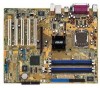
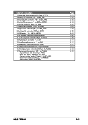
Internal connectors 1. CPU fan connector (4-pin CPU_FAN) 6. Digital audio connector (4-1 pin SPDIF_OUT) 8. ATX power connector (24-pin EATXPWR) 11. Optical audio connector (4-pin CD) 13. System panel connectors (... ATX12V) 12. Reset switch (Blue 2-pin RESET) Page 2-25 2-25 2-25 2-26 2-28 2-28 2-28 2-29 2-29 2-30 2-30 2-31 2-31 2-31 2-32 2-32 2-33 ASUS P5P800 2-5 Primary IDE connector (40-1 pin PRI_IDE) 3. Secondary IDE connector (40-1 pin SEC_IDE) 4. Chassis fan connector (3-pin CHA_FAN) 7. Serial port 2 connector (10-1 pin COM2) 9. Auxilliary audio...
Internal connectors 1. CPU fan connector (4-pin CPU_FAN) 6. Digital audio connector (4-1 pin SPDIF_OUT) 8. ATX power connector (24-pin EATXPWR) 11. Optical audio connector (4-pin CD) 13. System panel connectors (... ATX12V) 12. Reset switch (Blue 2-pin RESET) Page 2-25 2-25 2-25 2-26 2-28 2-28 2-28 2-29 2-29 2-30 2-30 2-31 2-31 2-31 2-32 2-32 2-33 ASUS P5P800 2-5 Primary IDE connector (40-1 pin PRI_IDE) 3. Secondary IDE connector (40-1 pin SEC_IDE) 4. Chassis fan connector (3-pin CHA_FAN) 7. Serial port 2 connector (10-1 pin COM2) 9. Auxilliary audio...
P5P800 User's manual English Edition E1906
Page 26
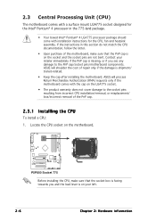
... socket. • The product warranty does not cover damage to the PnP cap/socket pins/motherboard components. Locate the CPU socket on the socket and the socket pins are not bent. ASUS will shoulder the cost of repair only if the damage is on your retailer immediately if the PnP cap is... on the motherboard. ® P5P800 P5P800 Socket 775 Before installing the CPU, make sure that the socket box is facing towards you see...
... socket. • The product warranty does not cover damage to the PnP cap/socket pins/motherboard components. Locate the CPU socket on the socket and the socket pins are not bent. ASUS will shoulder the cost of repair only if the damage is on your retailer immediately if the PnP cap is... on the motherboard. ® P5P800 P5P800 Socket 775 Before installing the CPU, make sure that the socket box is facing towards you see...
P5P800 User's manual English Edition E1906
Page 27
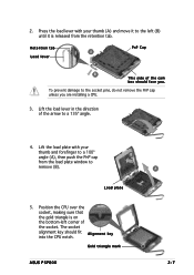
Lift the load lever in the direction of the cam box should fit A l i g n m e n t k e y into the CPU notch. The socket alignment key should face you are installing a CPU. 3. Lift the load plate with your thumb and forefinger to a 100º angle (A), then push the PnP cap B from the retention tab. ...PnP Cap B This side of the arrow to the socket pins, do not remove the PnP cap unless you . Load plate 5. Gold triangle mark ASUS P5P800 A 2-7 Press the load lever with your thumb (A) and move it is released from the load plate window to the left corner of the socket....
Lift the load lever in the direction of the cam box should fit A l i g n m e n t k e y into the CPU notch. The socket alignment key should face you are installing a CPU. 3. Lift the load plate with your thumb and forefinger to a 100º angle (A), then push the PnP cap B from the retention tab. ...PnP Cap B This side of the arrow to the socket pins, do not remove the PnP cap unless you . Load plate 5. Gold triangle mark ASUS P5P800 A 2-7 Press the load lever with your thumb (A) and move it is released from the load plate window to the left corner of the socket....
P5P800 User's manual English Edition E1906
Page 28
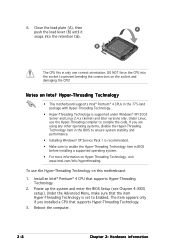
... in BIOS before installing a supported operating system. • For more information on the socket and damaging the CPU! DO NOT force the CPU into the retention tab. Under the Advanced Menu, make sure that the item Hyper-Threading Technology is supported under Windows® ...XP/2003 Server and Linux 2.4.x (kernel) and later versions only. If you installed a CPU that supports Hyper-Threading Technology. 2. Close the load plate (A), then A push the load lever (B) until it snaps into the socket to enable the...
... in BIOS before installing a supported operating system. • For more information on the socket and damaging the CPU! DO NOT force the CPU into the retention tab. Under the Advanced Menu, make sure that the item Hyper-Threading Technology is supported under Windows® ...XP/2003 Server and Linux 2.4.x (kernel) and later versions only. If you installed a CPU that supports Hyper-Threading Technology. 2. Close the load plate (A), then A push the load lever (B) until it snaps into the socket to enable the...
P5P800 User's manual English Edition E1906
Page 29
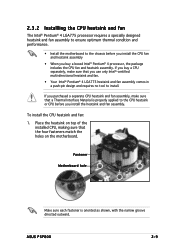
... ensure optimum thermal condition and performance. • Install the motherboard to the chassis before you buy a CPU separately, make sure that a Thermal Interface Material is oriented as shown, with the narrow groove directed outward. ASUS P5P800 2-9 Place the heatsink on the motherboard. If you use only Intel®-certified multi-directional heatsink and...
... ensure optimum thermal condition and performance. • Install the motherboard to the chassis before you buy a CPU separately, make sure that a Thermal Interface Material is oriented as shown, with the narrow groove directed outward. ASUS P5P800 2-9 Place the heatsink on the motherboard. If you use only Intel®-certified multi-directional heatsink and...

P5P800 User's manual English Edition E1906
Page 30
Hardware monitoring errors can occur if you fail to connect the CPU fan connector! R P5P800 CPU_FAN GND CPU FAN PWR CPU FAN IN CPU FAN PWM P5P800 CPU Fan connector Do not forget to plug this connector. 2-10 Chapter 2: Hardware information When the fan and heatsink assembly is in place. A A A B B B A 3. Push down two fasteners at a time in a diagonal sequence to secure the heatsink and fan B assembly in place, connect the CPU fan cable to the connector on the motherboard labeled CPU_FAN. 2.
Hardware monitoring errors can occur if you fail to connect the CPU fan connector! R P5P800 CPU_FAN GND CPU FAN PWR CPU FAN IN CPU FAN PWM P5P800 CPU Fan connector Do not forget to plug this connector. 2-10 Chapter 2: Hardware information When the fan and heatsink assembly is in place. A A A B B B A 3. Push down two fasteners at a time in a diagonal sequence to secure the heatsink and fan B assembly in place, connect the CPU fan cable to the connector on the motherboard labeled CPU_FAN. 2.
P5P800 User's manual English Edition E1906
Page 31
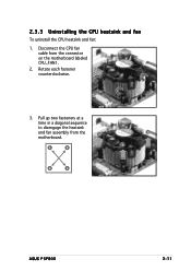
Disconnect the CPU fan cable from the A A motherboard. Pull up two fasteners at a time in a diagonal sequence to disengage the heatsink B and fan assembly from the connector on the motherboard labeled CPU_FAN1. 2. Rotate each fastener counterclockwise. 3. B A B B A ASUS P5P800 2-11 2.3.3 Uninstalling the CPU heatsink and fan To uninstall the CPU heatsink and fan: 1.
Disconnect the CPU fan cable from the A A motherboard. Pull up two fasteners at a time in a diagonal sequence to disengage the heatsink B and fan assembly from the connector on the motherboard labeled CPU_FAN1. 2. Rotate each fastener counterclockwise. 3. B A B B A ASUS P5P800 2-11 2.3.3 Uninstalling the CPU heatsink and fan To uninstall the CPU heatsink and fan: 1.
P5P800 User's manual English Edition E1906
Page 33
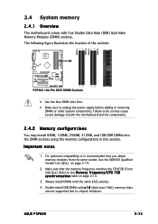
...recommended that the memory frequency matches the CPU FSB (Front Side Bus). Make ... power supply before adding or removing DIMMs or other system components. The following figure illustrates the location of the sockets: DIMM_A1 DIMM_A2 DIMM_B1 DIMM_B2 ® P5P800 P5P800 184-Pin DDR DIMM Sockets • Use the blue DIMM slots first. • Make sure to the M e m o r y f r e q u e n c y / C P U F... DDR DIMMs into the DIMM sockets using the memory configurations in this section. Important notes 1. ASUS P5P800 2-13 See the DDR400 Qualified Vendor List (QVL) on page 2-14. 3. 2.4 System ...
...recommended that the memory frequency matches the CPU FSB (Front Side Bus). Make ... power supply before adding or removing DIMMs or other system components. The following figure illustrates the location of the sockets: DIMM_A1 DIMM_A2 DIMM_B1 DIMM_B2 ® P5P800 P5P800 184-Pin DDR DIMM Sockets • Use the blue DIMM slots first. • Make sure to the M e m o r y f r e q u e n c y / C P U F... DDR DIMMs into the DIMM sockets using the memory configurations in this section. Important notes 1. ASUS P5P800 2-13 See the DDR400 Qualified Vendor List (QVL) on page 2-14. 3. 2.4 System ...
P5P800 User's manual English Edition E1906
Page 34
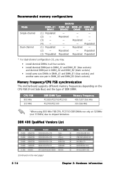
...SS DS Component HY5DU56822BT-D43 HY5DU56822BT-D43 HYB25D256800BT-5B HYB25D256809BT-5B D3208DL2T-5 D328DIB-50 K4H560838E-TCCC MT46V32M8TG-5BC MT46V32M8TG-5BC (Continued on the CPU FSB (Front Side Bus) and the type of DDR DIMM. Populated - Populated - - - Populated - Populated - Populated Populated ...MHz DDR DIMM Type PC3200/PC2700/PC2100 PC2700/PC2100 Memory Frequency 400/320*/266 MHz 333/266 MHz *When using 800 MHz FSB CPU, PC2700 DDR DIMMs run only at 320MHz (not 333MHz) due to chipset limitation. Recommended memory configurations Mode Single-channel Dual-channel DIMM_A1...
...SS DS Component HY5DU56822BT-D43 HY5DU56822BT-D43 HYB25D256800BT-5B HYB25D256809BT-5B D3208DL2T-5 D328DIB-50 K4H560838E-TCCC MT46V32M8TG-5BC MT46V32M8TG-5BC (Continued on the CPU FSB (Front Side Bus) and the type of DDR DIMM. Populated - Populated - - - Populated - Populated - Populated Populated ...MHz DDR DIMM Type PC3200/PC2700/PC2100 PC2700/PC2100 Memory Frequency 400/320*/266 MHz 333/266 MHz *When using 800 MHz FSB CPU, PC2700 DDR DIMMs run only at 320MHz (not 333MHz) due to chipset limitation. Recommended memory configurations Mode Single-channel Dual-channel DIMM_A1...
P5P800 User's manual English Edition E1906
Page 40
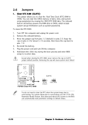
...settings to re-enter data. For system failure due to pins 2-3. Move the jumper cap from pins 1-2 (default) to overclocking, use the C.P.R. (CPU Parameter Recall) feature. Plug the power cord and turn ON the computer. 6. Except when clearing the RTC RAM, never remove the cap on pins 2-3... position. The onboard button cell battery powers the RAM data in CMOS. 2.6 Jumpers 1. Removing the cap will cause system boot failure! ® P5P800 P5P800 Clear RTC RAM CLRTC 12 23 Normal (Default) Clear CMOS You do not need to clear the RTC when the system hangs due to pins 1-2....
...settings to re-enter data. For system failure due to pins 2-3. Move the jumper cap from pins 1-2 (default) to overclocking, use the C.P.R. (CPU Parameter Recall) feature. Plug the power cord and turn ON the computer. 6. Except when clearing the RTC RAM, never remove the cap on pins 2-3... position. The onboard button cell battery powers the RAM data in CMOS. 2.6 Jumpers 1. Removing the cap will cause system boot failure! ® P5P800 P5P800 Clear RTC RAM CLRTC 12 23 Normal (Default) Clear CMOS You do not need to clear the RTC when the system hangs due to pins 1-2....
P5P800 User's manual English Edition E1906
Page 41
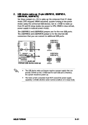
otherwise, the system would not power up from S1 sleep mode (CPU stopped, DRAM refreshed, system running in low power mode) using the connected USB devices. ASUS P5P800 2-21 Set to +5VSB to wake up . • The total current consumed must NOT exceed the power supply capability (+5VSB) whether under normal condition or ...
otherwise, the system would not power up from S1 sleep mode (CPU stopped, DRAM refreshed, system running in low power mode) using the connected USB devices. ASUS P5P800 2-21 Set to +5VSB to wake up . • The total current consumed must NOT exceed the power supply capability (+5VSB) whether under normal condition or ...
P5P800 User's manual English Edition E1906
Page 50
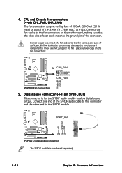
... Do not forget to connect the fan cables to the fan connectors on the fan connectors! ® P5P800 CPU_FAN GND CPU FAN PWR CPU FAN IN CPU FAN PWM CHA_FAN Rotation +12V GND P5P800 Fan connectors 5 . DO NOT place jumper caps on the motherboard, making sure that the black wire ...flow inside the system may damage the motherboard components. SPDIF_OUT +5V SPDIFOUT GND ® P5P800 P5P800 Digital audio connector The S/PDIF module is for the S/PDIF audio module to the S/PDIF module. CPU and Chassis fan connectors (4-pin CPU_FAN, CHA_FAN) The fan connectors support cooling fans of 350mA...
... Do not forget to connect the fan cables to the fan connectors on the fan connectors! ® P5P800 CPU_FAN GND CPU FAN PWR CPU FAN IN CPU FAN PWM CHA_FAN Rotation +12V GND P5P800 Fan connectors 5 . DO NOT place jumper caps on the motherboard, making sure that the black wire ...flow inside the system may damage the motherboard components. SPDIF_OUT +5V SPDIFOUT GND ® P5P800 P5P800 Digital audio connector The S/PDIF module is for the S/PDIF audio module to the S/PDIF module. CPU and Chassis fan connectors (4-pin CPU_FAN, CHA_FAN) The fan connectors support cooling fans of 350mA...
P5P800 User's manual English Edition E1906
Page 77
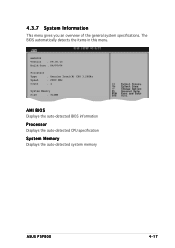
AMIBIOS Version : 08.00.10 Build Date : 04/07/04 Processor Type Speed Count : Genuine Intel(R) CPU 3.20GHz : 2800 MHz : 1 System Memory Size : 512MB AMI BIOS Displays the auto-detected BIOS information Processor Displays the auto-detected CPU specification System Memory Displays the auto-detected system memory ASUS P5P800 4-17 The BIOS automatically detects the items in this menu. 4.3.7 System Information This menu gives you an overview of the general system specifications.
AMIBIOS Version : 08.00.10 Build Date : 04/07/04 Processor Type Speed Count : Genuine Intel(R) CPU 3.20GHz : 2800 MHz : 1 System Memory Size : 512MB AMI BIOS Displays the auto-detected BIOS information Processor Displays the auto-detected CPU specification System Memory Displays the auto-detected system memory ASUS P5P800 4-17 The BIOS automatically detects the items in this menu. 4.3.7 System Information This menu gives you an overview of the general system specifications.


