
User Guide
Page 4
... off the computer 3-2 3.2.1 Using the OS shut down function 3-2 3.2.2 Using the dual function power switch 3-2 Chapter 4: BIOS setup 4.1 Managing and updating your BIOS 4-1 4.1.1 Creating a bootable floppy disk 4-1 4.1.2 AFUDOS utility 4-2 4.1.3 ASUS CrashFree BIOS 2 utility 4-5 4.1.4 ASUS Update utility 4-7 4.2 BIOS setup program 4-10 4.2.1 4.2.2 4.2.3 BIOS menu screen 4-11 Menu bar 4-11 Navigation keys 4-11 4.2.4 Menu items 4-12 4.2.5 Sub-menu items 4-12...
... off the computer 3-2 3.2.1 Using the OS shut down function 3-2 3.2.2 Using the dual function power switch 3-2 Chapter 4: BIOS setup 4.1 Managing and updating your BIOS 4-1 4.1.1 Creating a bootable floppy disk 4-1 4.1.2 AFUDOS utility 4-2 4.1.3 ASUS CrashFree BIOS 2 utility 4-5 4.1.4 ASUS Update utility 4-7 4.2 BIOS setup program 4-10 4.2.1 4.2.2 4.2.3 BIOS menu screen 4-11 Menu bar 4-11 Navigation keys 4-11 4.2.4 Menu items 4-12 4.2.5 Sub-menu items 4-12...

User Guide
Page 5
... Settings Configuration 4-34 4.6.3 Security 4-35 4.7 Exit menu 4-38 Chapter 5: RAID configuration 5.1 Setting up RAID 5-1 5.1.1 RAID definitions 5-1 5.1.2 Installing hard disk drives 5-2 5.1.3 Setting the RAID item in BIOS 5-2 5.1.4 RAID configuration utilities 5-3 5.2 LSI Logic Embedded SATA RAID Setup Utility 5-4 5.2.1 Creating a RAID 0 or RAID 1 set 5-5 5.2.2 Creating a RAID 10 set 5-11 5.2.3 Adding or viewing a RAID configuration...
... Settings Configuration 4-34 4.6.3 Security 4-35 4.7 Exit menu 4-38 Chapter 5: RAID configuration 5.1 Setting up RAID 5-1 5.1.1 RAID definitions 5-1 5.1.2 Installing hard disk drives 5-2 5.1.3 Setting the RAID item in BIOS 5-2 5.1.4 RAID configuration utilities 5-3 5.2 LSI Logic Embedded SATA RAID Setup Utility 5-4 5.2.1 Creating a RAID 0 or RAID 1 set 5-5 5.2.2 Creating a RAID 10 set 5-11 5.2.3 Adding or viewing a RAID configuration...
User Guide
Page 9
... Your product package may include optional documentation, such as warranty flyers, that may refer to the ASUS contact information. 2. Detailed descriptions of the BIOS parameters are not part of the switches, jumpers, and connectors on ASUS hardware and software products. How this guide This user guide contains the information you may have to...
... Your product package may include optional documentation, such as warranty flyers, that may refer to the ASUS contact information. 2. Detailed descriptions of the BIOS parameters are not part of the switches, jumpers, and connectors on ASUS hardware and software products. How this guide This user guide contains the information you may have to...

User Guide
Page 12
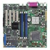
...Intel® ICH7R Southbridge supports: - 4 USB 2.0 ports (2 on the rear panel, 2 on the front panel) Special features ASUS Smart Fan ASUS CrashFree BIOS 2 ASUS MyLogo2 BIOS features AMI BIOS, 8 MB Flash ROM, Green, PnP, DMI, SMBIOS 2.3, WfM2.0, ACPI 2.0a Rear panel Internal connectors PS/2 keyboard port (... disk activity LED connector Ambient thermal sensor connector Serial port (COM2) connector Chassis intrusion connector ASUS server management (BMC) connector Ultra-320 SCSI connector (P5MT/SCSI model only) Power Requirement Form Factor Support CD contents SSI power supply (with 24-...
...Intel® ICH7R Southbridge supports: - 4 USB 2.0 ports (2 on the rear panel, 2 on the front panel) Special features ASUS Smart Fan ASUS CrashFree BIOS 2 ASUS MyLogo2 BIOS features AMI BIOS, 8 MB Flash ROM, Green, PnP, DMI, SMBIOS 2.3, WfM2.0, ACPI 2.0a Rear panel Internal connectors PS/2 keyboard port (... disk activity LED connector Ambient thermal sensor connector Serial port (COM2) connector Chassis intrusion connector ASUS server management (BMC) connector Ultra-320 SCSI connector (P5MT/SCSI model only) Power Requirement Form Factor Support CD contents SSI power supply (with 24-...
User Guide
Page 18
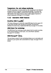
... feature allows you to personalize and add style to restore the original BIOS data from the support CD in case when the BIOS codes and data are corrupted. See page 4-5 for details. ASUS Smart Fan technology The ASUS Smart Fan technology smartly adjusts the fan speeds according to the system loading ...with customizable boot logos. See page 4-34 for timely failure detection. The ASIC monitors the voltage levels to prevent overheating and damage. ASUS MyLogo2™ This new feature present in the Winbond hardware monitor) to ensure stable supply of current for critical components.
... feature allows you to personalize and add style to restore the original BIOS data from the support CD in case when the BIOS codes and data are corrupted. See page 4-5 for details. ASUS Smart Fan technology The ASUS Smart Fan technology smartly adjusts the fan speeds according to the system loading ...with customizable boot logos. See page 4-34 for timely failure detection. The ASIC monitors the voltage levels to prevent overheating and damage. ASUS MyLogo2™ This new feature present in the Winbond hardware monitor) to ensure stable supply of current for critical components.

User Guide
Page 23
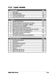
...B: Keyboard USBPW12 USB12 REAR_FAN1 25cm (9.8in) ATXPWR1 ATX12V1 CPU_FAN1 COM1 REAR_FAN2 CPU_FAN2 FM_CPU2 Intel E7230 FM_CPU1 LGA775 PARALLEL PORT ® P5MT LAN_EN1 LAN_EN2 VGA1 LAN1 LAN2 Broadcom BCM5721 Broadcom BCM5721 DDR2 DIMM_A1 (64 bit,240-pin module) DDR2 DIMM_A2 (64 bit,240-pin... Intel ICH7R SATA4 SATA3 SATA2 SATA1 RAID_SEL1 FRNT_FAN2 VGA_EN1 BMCSOCKET1 ATI RAGE XL VGA Controller Super I/O SB_PWR1 8Mbit Flash BIOS RECOVERY1 PCI4 BPSMB1 TRPWR1 AUX_PANEL1 BMCCONN1 HDLED1 CLRTC1 CR2032 3V Lithium Cell BUZZ1 CMOS Power USBPW34 USB34 PANEL1 Intel 6702 PXH...
...B: Keyboard USBPW12 USB12 REAR_FAN1 25cm (9.8in) ATXPWR1 ATX12V1 CPU_FAN1 COM1 REAR_FAN2 CPU_FAN2 FM_CPU2 Intel E7230 FM_CPU1 LGA775 PARALLEL PORT ® P5MT LAN_EN1 LAN_EN2 VGA1 LAN1 LAN2 Broadcom BCM5721 Broadcom BCM5721 DDR2 DIMM_A1 (64 bit,240-pin module) DDR2 DIMM_A2 (64 bit,240-pin... Intel ICH7R SATA4 SATA3 SATA2 SATA1 RAID_SEL1 FRNT_FAN2 VGA_EN1 BMCSOCKET1 ATI RAGE XL VGA Controller Super I/O SB_PWR1 8Mbit Flash BIOS RECOVERY1 PCI4 BPSMB1 TRPWR1 AUX_PANEL1 BMCCONN1 HDLED1 CLRTC1 CR2032 3V Lithium Cell BUZZ1 CMOS Power USBPW34 USB34 PANEL1 Intel 6702 PXH...
User Guide
Page 25
... Jumpers 1. Keyboard power (3-pin KBPWR1) 5. Gigabit LAN controller setting (3-pin LAN_EN1; SCSI controller setting (3-pin SCSI_EN1) (P5MT/SCSI model only) 9. VGA port 7. CPU sockets 2. DDR2 DIMM sockets 3. USB device wake-up (3-pin USBPW1, USBPW2) 4. Force BIOS recovery setting (3-pin RECOVERY1) Rear panel connectors 1. PCI/PCI-X/PCI Express slots 4. USB 2.0 ports 1 and 2 5. RAID...-45) port Page 2-11 2-15 2-20 2-20 Page 2-18 2-19 2-19 2-20 2-21 2-21 2-22 2-22 Page 2-23 2-23 2-23 2-23 2-23 2-23 2-23 2-23 ASUS P5MT Series 2-5 2.2.4 Layout contents Slots/Sockets 1.
... Jumpers 1. Keyboard power (3-pin KBPWR1) 5. Gigabit LAN controller setting (3-pin LAN_EN1; SCSI controller setting (3-pin SCSI_EN1) (P5MT/SCSI model only) 9. VGA port 7. CPU sockets 2. DDR2 DIMM sockets 3. USB device wake-up (3-pin USBPW1, USBPW2) 4. Force BIOS recovery setting (3-pin RECOVERY1) Rear panel connectors 1. PCI/PCI-X/PCI Express slots 4. USB 2.0 ports 1 and 2 5. RAID...-45) port Page 2-11 2-15 2-20 2-20 Page 2-18 2-19 2-19 2-20 2-21 2-21 2-22 2-22 Page 2-23 2-23 2-23 2-23 2-23 2-23 2-23 2-23 ASUS P5MT Series 2-5 2.2.4 Layout contents Slots/Sockets 1.
User Guide
Page 35
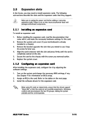
...Replace the system cover. 2.5.2 Configuring an expansion card After installing the expansion card, configure the it and make the necessary hardware settings for information on BIOS setup. 2. Assign an IRQ to the tables on shared slots, ensure that the drivers support "Share IRQ" or that they support. Refer to the...the screw for the expansion card. Remove the system unit cover (if your motherboard is completely seated on the system and change the necessary BIOS settings, if any. See Chapter 4 for the card. 2. When using PCI cards on the next page. 3. ASUS P5MT Series 2-15
...Replace the system cover. 2.5.2 Configuring an expansion card After installing the expansion card, configure the it and make the necessary hardware settings for information on BIOS setup. 2. Assign an IRQ to the tables on shared slots, ensure that the drivers support "Share IRQ" or that they support. Refer to the...the screw for the expansion card. Remove the system unit cover (if your motherboard is completely seated on the system and change the necessary BIOS settings, if any. See Chapter 4 for the card. 2. When using PCI cards on the next page. 3. ASUS P5MT Series 2-15

User Guide
Page 38
...) This jumper allows you to pins 2-3. Re-install the battery. 5. Removing the cap will cause system boot failure! ® LAN2 CLRTC1 12 23 Normal (Default) P5MT Series Clear RTC RAM Clear CMOS 2-18 Chapter 2: Hardware information To erase the RTC RAM: 1. You can clear the CMOS memory of date, time, and... system setup parameters by erasing the CMOS RTC RAM data. Hold down the key during the boot process and enter BIOS setup to pins 1-2. 4. Except when clearing the RTC RAM, never remove the cap on pins 2-3 for about 5~10 seconds, then move the cap back to...
...) This jumper allows you to pins 2-3. Re-install the battery. 5. Removing the cap will cause system boot failure! ® LAN2 CLRTC1 12 23 Normal (Default) P5MT Series Clear RTC RAM Clear CMOS 2-18 Chapter 2: Hardware information To erase the RTC RAM: 1. You can clear the CMOS memory of date, time, and... system setup parameters by erasing the CMOS RTC RAM data. Hold down the key during the boot process and enter BIOS setup to pins 1-2. 4. Except when clearing the RTC RAM, never remove the cap on pins 2-3 for about 5~10 seconds, then move the cap back to...

User Guide
Page 40
... you to enable or disable the keyboard wake-up the computer when you press a key on the +5VSB lead, and a corresponding setting in the BIOS. This feature requires an ATX power supply that can supply at least 1A on the keyboard (the default is the Space Bar). VGA controller setting... or disable the onboard ATI® RAGE-XL PCI VGA controller. 4. Set this jumper to pins 2-3 (+5VSB) to activate the VGA feature. ® LAN2 P5MT Series VGA setting VGA_EN1 2 1 Enable (Default) 3 2 Disable 2-20 Chapter 2: Hardware information KBPWR1 12 23 ® +5V +5VSB LAN2 (Default...
... you to enable or disable the keyboard wake-up the computer when you press a key on the +5VSB lead, and a corresponding setting in the BIOS. This feature requires an ATX power supply that can supply at least 1A on the keyboard (the default is the Space Bar). VGA controller setting... or disable the onboard ATI® RAGE-XL PCI VGA controller. 4. Set this jumper to pins 2-3 (+5VSB) to activate the VGA feature. ® LAN2 P5MT Series VGA setting VGA_EN1 2 1 Enable (Default) 3 2 Disable 2-20 Chapter 2: Hardware information KBPWR1 12 23 ® +5V +5VSB LAN2 (Default...

User Guide
Page 42
... onboard LSI 53C1020A PCI-X SCSI controller. LAN2 RECOVERY1 1 2 Normal (Default) P5MT Series BIOS recovery setting 2 3 BIOS recovery 2-22 Chapter 2: Hardware information SCSI controller setting (3-pin SCSI_EN1) (P5MT/SCSI model only) This jumper allows you to update the BIOS. 4. Prepare a floppy disk that contains the latest BIOS for the motherboard (xxxx-xxx.ROM) and the AFUDOS.EXE...
... onboard LSI 53C1020A PCI-X SCSI controller. LAN2 RECOVERY1 1 2 Normal (Default) P5MT Series BIOS recovery setting 2 3 BIOS recovery 2-22 Chapter 2: Hardware information SCSI controller setting (3-pin SCSI_EN1) (P5MT/SCSI model only) This jumper allows you to update the BIOS. 4. Prepare a floppy disk that contains the latest BIOS for the motherboard (xxxx-xxx.ROM) and the AFUDOS.EXE...
User Guide
Page 45
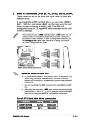
... LAN2 RSATA_RXN4 RSATA_RXN2 GND GND SATA3 SATA1 GND RSATA_TXP3 RSATA_TXN3 GND RSATA_RXP3 RSATA_RXN3 GND P5MT Series SATA connectors GND RSATA_TXP1 RSATA_TXN1 GND RSATA_RXP1 RSATA_RXN1 GND Important notes on the ...Intel® ICH7R Southbridge. Serial ATA hard disk drive connection Connector Setting Use SATA1/SATA2 SATA3/SATA4 Master Slave Boot disk Data disk ASUS P5MT Series 2-25 These connectors are for the Serial ATA signal cables for each RAID 0 or RAID 1 set the C o n f...before using the connectors in the BIOS to the SATA1 or SATA2 connector.
... LAN2 RSATA_RXN4 RSATA_RXN2 GND GND SATA3 SATA1 GND RSATA_TXP3 RSATA_TXN3 GND RSATA_RXP3 RSATA_RXN3 GND P5MT Series SATA connectors GND RSATA_TXP1 RSATA_TXN1 GND RSATA_RXP1 RSATA_RXN1 GND Important notes on the ...Intel® ICH7R Southbridge. Serial ATA hard disk drive connection Connector Setting Use SATA1/SATA2 SATA3/SATA4 Master Slave Boot disk Data disk ASUS P5MT Series 2-25 These connectors are for the Serial ATA signal cables for each RAID 0 or RAID 1 set the C o n f...before using the connectors in the BIOS to the SATA1 or SATA2 connector.

User Guide
Page 51
...connector is for easy connection. Connect the HDD Activity LED cable to this connector. Pressing the power button turns the system on the BIOS settings. ASUS P5MT Series 2-31 Pressing the power switch for more than four seconds while the system is ON turns the system OFF. • Reset... power. ® POWERLED+ GND POWERLEDMLED+ MLEDNC +5V GND GND SPKROUT HDLED+ HDLEDNMIBTN# GND POWERBTN# GND NC RESETBTN# GND LAN2 PANEL1 P5MT Series System panel connector The system panel connector is for the system power button. Connect the chassis power LED cable to this connector. The...
...connector is for easy connection. Connect the HDD Activity LED cable to this connector. Pressing the power button turns the system on the BIOS settings. ASUS P5MT Series 2-31 Pressing the power switch for more than four seconds while the system is ON turns the system OFF. • Reset... power. ® POWERLED+ GND POWERLEDMLED+ MLEDNC +5V GND GND SPKROUT HDLED+ HDLEDNMIBTN# GND POWERBTN# GND NC RESETBTN# GND LAN2 PANEL1 P5MT Series System panel connector The system panel connector is for the system power button. Connect the chassis power LED cable to this connector. The...

User Guide
Page 55
...cord to a power outlet that all the connections, replace the system case cover. 2. Monitor b. After applying power, the system power LED on . ASUS P5MT Series 3-1 For systems withATX power supplies, the system LED lights up or switch between orange and green after the system LED turns on the system... the instructions in the following order: a. The system then runs the power-on , hold down the key to enter the BIOS Setup. AMI BIOS beep codes Beep Description One beep Two continuous beeps followed by two short beeps Two continuous beeps followed by four short beeps Error...
...cord to a power outlet that all the connections, replace the system case cover. 2. Monitor b. After applying power, the system power LED on . ASUS P5MT Series 3-1 For systems withATX power supplies, the system LED lights up or switch between orange and green after the system LED turns on the system... the instructions in the following order: a. The system then runs the power-on , hold down the key to enter the BIOS Setup. AMI BIOS beep codes Beep Description One beep Two continuous beeps followed by two short beeps Two continuous beeps followed by four short beeps Error...

User Guide
Page 56
.... 3. Pressing the power switch for less than four seconds lets the system enter the soft-off mode regardless of the BIOS setting. Click the T u r n O f f button to soft-off mode, depending on the BIOS setting. If you are using Windows® 2000: 1. Click the S t a r t button then select T u r n O f f C o m p u t e r . 2. 3.2 Powering off the computer 3.2.1 Using the...
.... 3. Pressing the power switch for less than four seconds lets the system enter the soft-off mode regardless of the BIOS setting. Click the T u r n O f f button to soft-off mode, depending on the BIOS setting. If you are using Windows® 2000: 1. Click the S t a r t button then select T u r n O f f C o m p u t e r . 2. 3.2 Powering off the computer 3.2.1 Using the...

User Guide
Page 57
Detailed descriptions of the BIOS parameters are also provided. 4 BIOS setup This chapter tells how to change the system settings through the BIOS Setup menus.
Detailed descriptions of the BIOS parameters are also provided. 4 BIOS setup This chapter tells how to change the system settings through the BIOS Setup menus.

User Guide
Page 58
Chapter summary 4 4.1 Managing and updating your BIOS 4-1 4.2 BIOS setup program 4-10 4.3 Main menu 4-13 4.4 Advanced menu 4-18 4.5 Power menu 4-28 4.6 Boot menu 4-33 4.7 Exit menu 4-38 ASUS P5MT Series
Chapter summary 4 4.1 Managing and updating your BIOS 4-1 4.2 BIOS setup program 4-10 4.3 Main menu 4-13 4.4 Advanced menu 4-18 4.5 Power menu 4-28 4.6 Boot menu 4-33 4.7 Exit menu 4-38 ASUS P5MT Series

User Guide
Page 59
... MB floppy disk to the corresponding sections for details on these utilities. e. A S U S U p d a t e (Updates the BIOS in case you to manage and update the motherboard Basic Input/Output System (BIOS) setup. 1. b. b. ASUS P5MT Series 4-1 Do either one of the original motherboard BIOS file to a bootable floppy disk in Windows® environment.) Refer to the floppy disk...
... MB floppy disk to the corresponding sections for details on these utilities. e. A S U S U p d a t e (Updates the BIOS in case you to manage and update the motherboard Basic Input/Output System (BIOS) setup. 1. b. b. ASUS P5MT Series 4-1 Do either one of the original motherboard BIOS file to a bootable floppy disk in Windows® environment.) Refer to the floppy disk...

User Guide
Page 60
.... All rights reserved. ok A:\> The utility returns to save the file. • The succeeding BIOS screens are for the extension name. The utility copies the current BIOS file to the bootable floppy disk you created earlier. 2. Version 1.19(ASUS V2.07(03.11.24BB)) Copyright (C) 2002 American Megatrends, Inc. Copy the AFUDOS utility...
.... All rights reserved. ok A:\> The utility returns to save the file. • The succeeding BIOS screens are for the extension name. The utility copies the current BIOS file to the bootable floppy disk you created earlier. 2. Version 1.19(ASUS V2.07(03.11.24BB)) Copyright (C) 2002 American Megatrends, Inc. Copy the AFUDOS utility...

User Guide
Page 61
... /iP5MT.rom Use the appropriate BIOS file depending on your motherboard model (e.g. Version 1.19(ASUS V2.07(03.11.24BB)) Copyright (C) 2002 American Megatrends, Inc. done Reading flash ...... Save the BIOS file to type the exact BIOS filename at the prompt type: ...afudos /i[filename] /pbnc where [filename] is the latest or the original BIOS file on a piece of paper. You need to a bootable floppy disk. P5MT.ROM or P5MTSCSI.ROM) 4. Do not turn off power during flash BIOS Reading file ....... Erasing flash ...... ASUS P5MT...
... /iP5MT.rom Use the appropriate BIOS file depending on your motherboard model (e.g. Version 1.19(ASUS V2.07(03.11.24BB)) Copyright (C) 2002 American Megatrends, Inc. done Reading flash ...... Save the BIOS file to type the exact BIOS filename at the prompt type: ...afudos /i[filename] /pbnc where [filename] is the latest or the original BIOS file on a piece of paper. You need to a bootable floppy disk. P5MT.ROM or P5MTSCSI.ROM) 4. Do not turn off power during flash BIOS Reading file ....... Erasing flash ...... ASUS P5MT...


