
Motherboard Installation Guide
Page 10
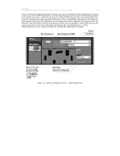
... Configuration Panel: As Figure 11 shows, there are dependent upon the button that can select which playback or recording device to receive the same audio signals as the front speakers. The user can also configure the headphone to be selected: "Equalizer" or "Bass Management". System Information Panel: As Figure 21 shows...
... Configuration Panel: As Figure 11 shows, there are dependent upon the button that can select which playback or recording device to receive the same audio signals as the front speakers. The user can also configure the headphone to be selected: "Equalizer" or "Bass Management". System Information Panel: As Figure 21 shows...
Motherboard Installation Guide
Page 17
... is set the low frequency limit for front-left speaker and change the "Cutoff Frequency" to control the low frequency limits for a speaker, any audio signal below the limit will be configured to the subwoofer. User Guide VT1708A VIA HD Audio Adeck For Windows 2000, Windows XP & Server 2003 17 Figure...
... is set the low frequency limit for front-left speaker and change the "Cutoff Frequency" to control the low frequency limits for a speaker, any audio signal below the limit will be configured to the subwoofer. User Guide VT1708A VIA HD Audio Adeck For Windows 2000, Windows XP & Server 2003 17 Figure...

User Guide
Page 7
... the crossed out wheeled bin indicates that the power cables for disposal of the electrical outlet you add a device. • Before connecting or removing signal cables from the motherboard, ensure that came with the product, contact a qualified service technician or your retailer. Contact a qualified service technician or your retailer. Check local regulations...
... the crossed out wheeled bin indicates that the power cables for disposal of the electrical outlet you add a device. • Before connecting or removing signal cables from the motherboard, ensure that came with the product, contact a qualified service technician or your retailer. Contact a qualified service technician or your retailer. Check local regulations...
User Guide
Page 39
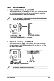
ASUS P5KPL-CM 1-27 Insert one end of the S/PDIF audio cable to this connector, then connect the other end to the S/PDIF module. +5V SPDIFOUT GND R P5KPL-CM SPDIF_OUT P5KPL-CM Digital Audio Connector The S/PDIF out module is removed to allow digital sound output. Digital Audio connector ...the signal connector at the back of the cable to this connector and the other end to PIN 1. Connect one end of the floppy disk drive. 1.10.2 Internal connectors 1. FLOPPY R P5KPL-CM PIN 1 NOTE: Orient the red markings on the connector is purchased separately. P5KPL-CM Floppy...
ASUS P5KPL-CM 1-27 Insert one end of the S/PDIF audio cable to this connector, then connect the other end to the S/PDIF module. +5V SPDIFOUT GND R P5KPL-CM SPDIF_OUT P5KPL-CM Digital Audio Connector The S/PDIF out module is removed to allow digital sound output. Digital Audio connector ...the signal connector at the back of the cable to this connector and the other end to PIN 1. Connect one end of the floppy disk drive. 1.10.2 Internal connectors 1. FLOPPY R P5KPL-CM PIN 1 NOTE: Orient the red markings on the connector is purchased separately. P5KPL-CM Floppy...
User Guide
Page 40
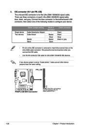
...motherboard's IDE connector, then select one of device(s) Master Slave Master Slave Cable connector Black Black Gray Black or gray • Pin 20 on the Ultra DMA cable connector. There are three connectors on the ID ribbon cable to PIN 1. 1-28 Chapter 1: Product introduction PRI_IDE R PIN1 P5KPL-CM P5KPL-CM... IDE Connector NOTE: Orient the red markings (usually zigzag) on each Ultra DMA 100/66/33 signal cable: blue, black, and gray. Single device Two devices Driver Jumper ...
...motherboard's IDE connector, then select one of device(s) Master Slave Master Slave Cable connector Black Black Gray Black or gray • Pin 20 on the Ultra DMA cable connector. There are three connectors on the ID ribbon cable to PIN 1. 1-28 Chapter 1: Product introduction PRI_IDE R PIN1 P5KPL-CM P5KPL-CM... IDE Connector NOTE: Orient the red markings (usually zigzag) on each Ultra DMA 100/66/33 signal cable: blue, black, and gray. Single device Two devices Driver Jumper ...
User Guide
Page 41
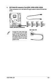
Or you may connect the right-angle side of SATA signal cable to avoid mechanical conflict with huge graphics cards. right angle side ASUS P5KPL-CM 1-29 R P5KPL-CM P5KPL-CM SATA Connectors SATA1 SATA3 SATA2 SATA4 GND RSATA_RXP1 RSATA_RXN1 GND RSATA_TXN1 RSATA_TXP1 GND GND RSATA_RXP2 RSATA_RXN2 GND RSATA_TXN2 RSATA_TXP2 GND GND RSATA_RXP3 RSATA_RXN3 GND RSATA_TXN3 ... cable to the onboard SATA port to SATA device. ICH7 Serial ATA connectors (7-pin SATA1, SATA2, SATA3, SATA4) These connectors are for the Serial ATA signal cables for Serial ATA hard disk drives. 4.
Or you may connect the right-angle side of SATA signal cable to avoid mechanical conflict with huge graphics cards. right angle side ASUS P5KPL-CM 1-29 R P5KPL-CM P5KPL-CM SATA Connectors SATA1 SATA3 SATA2 SATA4 GND RSATA_RXP1 RSATA_RXN1 GND RSATA_TXN1 RSATA_TXP1 GND GND RSATA_RXP2 RSATA_RXN2 GND RSATA_TXN2 RSATA_TXP2 GND GND RSATA_RXP3 RSATA_RXN3 GND RSATA_TXN3 ... cable to the onboard SATA port to SATA device. ICH7 Serial ATA connectors (7-pin SATA1, SATA2, SATA3, SATA4) These connectors are for the Serial ATA signal cables for Serial ATA hard disk drives. 4.

User Guide
Page 44
... sensor or switch. The chassis intrusion sensor or switch sends a high-level signal to [HD Audio]. R +5VSB_MB Chassis Signal GND P5KPL-CM CHASSIS P5KPL-CM Intrusion Connector (Default) 9. 8. Remove the jumper caps only when you want... to connect a High Definition front panel audio module to this connector, set the Front Panel Support Type item in the BIOS to this connector is set to use the chassis intrusion detection feature. Connect one end of the motherboard...
... sensor or switch. The chassis intrusion sensor or switch sends a high-level signal to [HD Audio]. R +5VSB_MB Chassis Signal GND P5KPL-CM CHASSIS P5KPL-CM Intrusion Connector (Default) 9. 8. Remove the jumper caps only when you want... to connect a High Definition front panel audio module to this connector, set the Front Panel Support Type item in the BIOS to this connector is set to use the chassis intrusion detection feature. Connect one end of the motherboard...

