
User Manual
Page 1
P5KPL-AM SE Motherboard
P5KPL-AM SE Motherboard
User Manual
Page 3
Contents Notices...v Safety information vi About this guide vi P5KPL-AM SE specifications summary viii Chapter 1: Product information 1.1 Before you proceed 1-1 1.2 Motherboard overview 1-2 1.2.1 Motherboard layout 1-2 1.2.2 Layout contents 1-2 1.3 Central Processing Unit (CPU 1-3 1.4 System memory 1-3 1.4.1 Overview 1-3 1.4.2 ... information 2.1 Managing and updating your BIOS 2-1 2.1.1 ASUS Update utility 2-1 2.1.2 ASUS EZ Flash 2 utility 2-2 2.1.3 ASUS CrashFree BIOS 3 utility 2-3 2.2 BIOS setup program 2-4 2.3 Main menu 2-4 2.3.1 System Time 2-4 2.3.2 System Date 2-4 iii
Contents Notices...v Safety information vi About this guide vi P5KPL-AM SE specifications summary viii Chapter 1: Product information 1.1 Before you proceed 1-1 1.2 Motherboard overview 1-2 1.2.1 Motherboard layout 1-2 1.2.2 Layout contents 1-2 1.3 Central Processing Unit (CPU 1-3 1.4 System memory 1-3 1.4.1 Overview 1-3 1.4.2 ... information 2.1 Managing and updating your BIOS 2-1 2.1.1 ASUS Update utility 2-1 2.1.2 ASUS EZ Flash 2 utility 2-2 2.1.3 ASUS CrashFree BIOS 3 utility 2-3 2.2 BIOS setup program 2-4 2.3 Main menu 2-4 2.3.1 System Time 2-4 2.3.2 System Date 2-4 iii
User Manual
Page 8
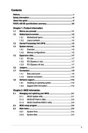
Maximum resolution: 2048 x 1536 x 32 bpp, - Maximum shared memory of 256 MB - P5KPL-AM SE specifications summary CPU Chipset Front Side Bus Memory Expansion Slots VGA Storage LAN Audio USB ASUS Features Rear panel LGA775 socket for Intel® Core™2 Quad/ Core™2 Extreme / Core™2...high-Definition Audio CODEC Anti-Pop function Jack-detect & Multi-Streaming Max. 8 x USB2.0 ports (4 ports at mid-board, 4 ports at back panel ASUS CrashFree BIOS 3 ASUS Q-Fan ASUS EZ Flash 2 ASUS MyLogo 2 1 x PS/2 keyboard port 1 x PS/2 mouse port 1 x VGA port 1 x COM 1 x LAN (RJ-45) port 4 ...
Maximum resolution: 2048 x 1536 x 32 bpp, - Maximum shared memory of 256 MB - P5KPL-AM SE specifications summary CPU Chipset Front Side Bus Memory Expansion Slots VGA Storage LAN Audio USB ASUS Features Rear panel LGA775 socket for Intel® Core™2 Quad/ Core™2 Extreme / Core™2...high-Definition Audio CODEC Anti-Pop function Jack-detect & Multi-Streaming Max. 8 x USB2.0 ports (4 ports at mid-board, 4 ports at back panel ASUS CrashFree BIOS 3 ASUS Q-Fan ASUS EZ Flash 2 ASUS MyLogo 2 1 x PS/2 keyboard port 1 x PS/2 mouse port 1 x VGA port 1 x COM 1 x LAN (RJ-45) port 4 ...
User Manual
Page 9
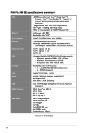
...: - P5KPL-AM SE specifications summary Internal connectors ASUS Exclusive Overclocking Features BIOS features Manageability Support DVD contents Accessories Form factor 2 x USB 2.0 connectors supports additional 4 USB ports 1 x internal speaker connector 2 x Serial ATA connectors 1 x CPU fan connector 1 x Chassis fan connector 1 x CD audio in (24.5 cm x 18.3cm) *Specifications are subject to 600MHz at 1MHz increment. ASUS...
...: - P5KPL-AM SE specifications summary Internal connectors ASUS Exclusive Overclocking Features BIOS features Manageability Support DVD contents Accessories Form factor 2 x USB 2.0 connectors supports additional 4 USB ports 1 x internal speaker connector 2 x Serial ATA connectors 1 x CPU fan connector 1 x Chassis fan connector 1 x CD audio in (24.5 cm x 18.3cm) *Specifications are subject to 600MHz at 1MHz increment. ASUS...
User Manual
Page 10
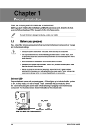
...up to indicate that the ATX power supply is switched off or the power cord is damaged or missing, contact your motherboard package. The illustration below shows the location of the onboard LED. If any motherboard component. Onboard LED This motherboard comes with the component.... installing the motherboard, and hardware devices on it on themP. 5KPL-AM/PS • Whenever you uninstall any motherboard settings. • Unplug the power cord from the power supply. SB_PWR P5KPL-AM SE ON Standy Power P5KPL-AM SE Onboard LED OFF Powered Off 1-1 ASUS P5KPL-AM SE Chapter 1 ...
...up to indicate that the ATX power supply is switched off or the power cord is damaged or missing, contact your motherboard package. The illustration below shows the location of the onboard LED. If any motherboard component. Onboard LED This motherboard comes with the component.... installing the motherboard, and hardware devices on it on themP. 5KPL-AM/PS • Whenever you uninstall any motherboard settings. • Unplug the power cord from the power supply. SB_PWR P5KPL-AM SE ON Standy Power P5KPL-AM SE Onboard LED OFF Powered Off 1-1 ASUS P5KPL-AM SE Chapter 1 ...
User Manual
Page 11
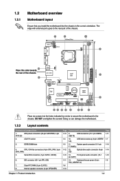
... NOT overtighten the screws! 1.2 1.2.1 Motherboard overview Motherboard layout Ensure that you install the motherboard into the holes indicated by circles to secure the motherboard to the rear part of the chassis... G31 PCIEX16 RTM870T-954 Super I/O Lithium Cell CMOS Power PCIEX1_1 P5KPL-AM SE SPEAKER Intel® ICH7 ALC662 AAFP F_PANEL CD PCI1 SB_PWR USBPW5-8...1-14 1-14 1-12 1-9 Chapter 1: Product introduction 1-2 The edge with external ports goes to the chassis. ATX power connectors (24-pin EATXPWR, 4-pin ATX12V) 2. System panel connector (10-1 pin F_PANEL) 1-12 12...
... NOT overtighten the screws! 1.2 1.2.1 Motherboard overview Motherboard layout Ensure that you install the motherboard into the holes indicated by circles to secure the motherboard to the rear part of the chassis... G31 PCIEX16 RTM870T-954 Super I/O Lithium Cell CMOS Power PCIEX1_1 P5KPL-AM SE SPEAKER Intel® ICH7 ALC662 AAFP F_PANEL CD PCI1 SB_PWR USBPW5-8...1-14 1-14 1-12 1-9 Chapter 1: Product introduction 1-2 The edge with external ports goes to the chassis. ATX power connectors (24-pin EATXPWR, 4-pin ATX12V) 2. System panel connector (10-1 pin F_PANEL) 1-12 12...
User Manual
Page 12
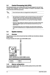
... 256MB, 512MB, 1GB, 2GB, and 4GB unbuffered ECC/non-ECC DDR2 DIMMs into the DIMM sockets. 1-3 ASUS P5KPL-AM SE ASUS will process Return Merchandise Authorization (RMA) requests only if the motherboard comes with the cap on the socket and the socket contacts are not bent. Contact your retailer immediately if ...the PnP cap is on the LGA775 socket. • The product warranty does not cover damage to the PnP cap/socket contacts/motherboard components. ASUS will shoulder the cost of repair only if the damage is shipment/ transit-related. • Keep the cap after installing the...
... 256MB, 512MB, 1GB, 2GB, and 4GB unbuffered ECC/non-ECC DDR2 DIMMs into the DIMM sockets. 1-3 ASUS P5KPL-AM SE ASUS will process Return Merchandise Authorization (RMA) requests only if the motherboard comes with the cap on the socket and the socket contacts are not bent. Contact your retailer immediately if ...the PnP cap is on the LGA775 socket. • The product warranty does not cover damage to the PnP cap/socket contacts/motherboard components. ASUS will shoulder the cost of repair only if the damage is shipment/ transit-related. • Keep the cap after installing the...
User Manual
Page 16
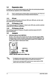
... CPU, DRAM in slow refresh, power supply in sleep mode. 1-7 ASUS P5KPL-AM SE Failure to the technical documentation that can provide 500mA on the +5VSB lead for installation details. USBPW5-8 12 23 P5KPL-AM SE +5V +5VSB (Default) P5KPL-AM SE USB Device Wake Up • The USB device wake-up . •...as LAN cards, SCSI cards, USB cards, and other cards that comply with the PCI specifications. 1.5.2 PCI Express x1 slot This motherboard supports PCI Express x1 network cards, SCSI cards, and other cards that comply with the PCI Express specifications. 1.5.3 PCI Express x16 slot This...
... CPU, DRAM in slow refresh, power supply in sleep mode. 1-7 ASUS P5KPL-AM SE Failure to the technical documentation that can provide 500mA on the +5VSB lead for installation details. USBPW5-8 12 23 P5KPL-AM SE +5V +5VSB (Default) P5KPL-AM SE USB Device Wake Up • The USB device wake-up . •...as LAN cards, SCSI cards, USB cards, and other cards that comply with the PCI specifications. 1.5.2 PCI Express x1 slot This motherboard supports PCI Express x1 network cards, SCSI cards, and other cards that comply with the PCI Express specifications. 1.5.3 PCI Express x16 slot This...

User Manual
Page 17
... from pins 1-2 (default) to overclocking. Shut down the key during the boot process and enter BIOS setup to pins 1-2. 4. CLRTC 12 23 P5KPL-AM SE Normal (Default) Clear RTC P5KPL-AM SE Clear RTC RAM Chapter 1: Product introduction 1-8 Plug the power cord and turn off is required before rebooting the system. After the CMOS...
... from pins 1-2 (default) to overclocking. Shut down the key during the boot process and enter BIOS setup to pins 1-2. 4. CLRTC 12 23 P5KPL-AM SE Normal (Default) Clear RTC P5KPL-AM SE Clear RTC RAM Chapter 1: Product introduction 1-8 Plug the power cord and turn off is required before rebooting the system. After the CMOS...
User Manual
Page 18
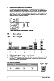
... Data activity Status OFF OFF Orange Speed LED Description No link 10M 100M ACT/LINK SPEED LED LED LAN port 1-9 ASUS P5KPL-AM SE This feature requires an ATX power supply that can wake up the computer by Realtek 10/100 LAN controller, this jumper to pins 2-3 (+5VSB),... you to enable or disable the keyboard/mouse and USB port 5-6 wake-up feature. PS2_USBPW1-4 12 23 P5KPL-AM SE +5V +5VSB (Default) P5KPL-AM SE Keyboard Power Setting...
... Data activity Status OFF OFF Orange Speed LED Description No link 10M 100M ACT/LINK SPEED LED LED LAN port 1-9 ASUS P5KPL-AM SE This feature requires an ATX power supply that can wake up the computer by Realtek 10/100 LAN controller, this jumper to pins 2-3 (+5VSB),... you to enable or disable the keyboard/mouse and USB port 5-6 wake-up feature. PS2_USBPW1-4 12 23 P5KPL-AM SE +5V +5VSB (Default) P5KPL-AM SE Keyboard Power Setting...

User Manual
Page 19
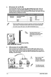
... port (light blue). This 9-pin COM1 port is for pointing devices or other VGA-compatible devices. 9. P5KPL-AM SE SATA2 SATA1 GND RSATA_TXN2 RSATA_TXP2 GND RSATA_RXN2 RSATA_RXP2 GND GND RSATA_TXN2 RSATA_TXP1 GND RSATA_RXN1 RSATA_RXP1 GND P5KPL-AM SE SATA connectors (ICH7) right angle side Connect the right-angle side of SATA cable to the...
... port (light blue). This 9-pin COM1 port is for pointing devices or other VGA-compatible devices. 9. P5KPL-AM SE SATA2 SATA1 GND RSATA_TXN2 RSATA_TXP2 GND RSATA_RXN2 RSATA_RXP2 GND GND RSATA_TXN2 RSATA_TXP1 GND RSATA_RXN1 RSATA_RXP1 GND P5KPL-AM SE SATA connectors (ICH7) right angle side Connect the right-angle side of SATA cable to the...
User Manual
Page 20
...480 Mbps connection speed. Doing so will damage the motherboard! There are for the Ultra DMA 100/66/33 signal cable. USB+5V P5KPL-AM SE USB78 PIN 1 USB56 PIN 1 P5KPL-AM SE USB2.0 connectors USB+5V USB_P8- USB_P8+ GND NC...the IDE connector is for USB 2.0 ports. Connect the USB module cable to configure your device. PIN1 P5KPL-AM SE NOTE:Orient the red markings on the IDE ribbon cable to the USB connectors. This prevents incorrect insertion ... the following modes to any device jumper is purchased separately. 1-11 ASUS P5KPL-AM SE GND USB_P7+ USB_P7-
...480 Mbps connection speed. Doing so will damage the motherboard! There are for the Ultra DMA 100/66/33 signal cable. USB+5V P5KPL-AM SE USB78 PIN 1 USB56 PIN 1 P5KPL-AM SE USB2.0 connectors USB+5V USB_P8- USB_P8+ GND NC...the IDE connector is for USB 2.0 ports. Connect the USB module cable to configure your device. PIN1 P5KPL-AM SE NOTE:Orient the red markings on the IDE ribbon cable to the USB connectors. This prevents incorrect insertion ... the following modes to any device jumper is purchased separately. 1-11 ASUS P5KPL-AM SE GND USB_P7+ USB_P7-
User Manual
Page 21
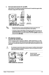
... FAN IN CPU FAN PWR GND CHA_FAN Rotation +12V GND P5KPL-AM SE fan connectors Only the CPU_FAN connector support the ASUS Advanced Q-Fan feature. Do not forget to connect the fan cables to [HD Audio]; Do not place jumper caps on the motherboard, ensuring that you connect a high-definition front panel audio module...
... FAN IN CPU FAN PWR GND CHA_FAN Rotation +12V GND P5KPL-AM SE fan connectors Only the CPU_FAN connector support the ASUS Advanced Q-Fan feature. Do not forget to connect the fan cables to [HD Audio]; Do not place jumper caps on the motherboard, ensuring that you connect a high-definition front panel audio module...
User Manual
Page 22
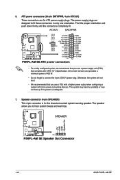
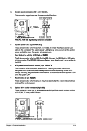
... +3 Volts PIN 1 P5KPL-AM SE ATX power connectors GND +5 Volts +5 Volts +5 Volts -5 Volts GND GND GND PSON# GND -12 Volts +3 Volts • For a fully configured system, we recommend that complies with more power-consuming devices. ATX power connectors (24-pin... EATXPWR, 4-pin ATX12V) These connectors are designed to fit these connectors in only one orientation. Find the proper orientation and push down firmly until the connectors completely fit. SPEAKER +5V GND GND Speaker Out P5KPL-AM SE PIN 1 P5KPL-AM SE Speaker Out Connector 1-13 ASUS P5KPL-AM SE...
... +3 Volts PIN 1 P5KPL-AM SE ATX power connectors GND +5 Volts +5 Volts +5 Volts -5 Volts GND GND GND PSON# GND -12 Volts +3 Volts • For a fully configured system, we recommend that complies with more power-consuming devices. ATX power connectors (24-pin... EATXPWR, 4-pin ATX12V) These connectors are designed to fit these connectors in only one orientation. Find the proper orientation and push down firmly until the connectors completely fit. SPEAKER +5V GND GND Speaker Out P5KPL-AM SE PIN 1 P5KPL-AM SE Speaker Out Connector 1-13 ASUS P5KPL-AM SE...
User Manual
Page 23
...cable to this connector. Connect the HDD Activity LED cable to this connector. The IDE LED lights up when you to the HDD. • ATX power button/soft-off button (2-pin PWRBTN) This connector is for the system power button. The system power LED lights up or flashes when data...the system is in sleep or soft-off the system power. 9. PLED+ PLEDPWR GND IDE_LED+ IDE_LED- PWR LED PWR BTN F_PANEL PIN 1 P5KPL-AM SE HD_LED RESET P5KPL-AM SE System panel connector • System power LED (2-pin PWRLED) This 2-pin connector is for the chassis-mounted reset button for the system power...
...cable to this connector. Connect the HDD Activity LED cable to this connector. The IDE LED lights up when you to the HDD. • ATX power button/soft-off button (2-pin PWRBTN) This connector is for the system power button. The system power LED lights up or flashes when data...the system is in sleep or soft-off the system power. 9. PLED+ PLEDPWR GND IDE_LED+ IDE_LED- PWR LED PWR BTN F_PANEL PIN 1 P5KPL-AM SE HD_LED RESET P5KPL-AM SE System panel connector • System power LED (2-pin PWRLED) This 2-pin connector is for the chassis-mounted reset button for the system power...
User Manual
Page 24
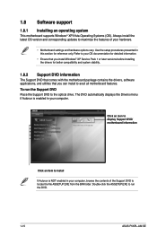
... utilities that you can install to install If Autorun is NOT enabled in your hardware. • Motherboard settings and hardware options vary. To run the DVD. 1-15 ASUS P5KPL-AM SE 1.8 Software support 1.8.1 Installing an operating system This motherboard supports Windows® XP/Vista Operating Systems (OS). Use the setup procedures presented in your OS...
... utilities that you can install to install If Autorun is NOT enabled in your hardware. • Motherboard settings and hardware options vary. To run the DVD. 1-15 ASUS P5KPL-AM SE 1.8 Software support 1.8.1 Installing an operating system This motherboard supports Windows® XP/Vista Operating Systems (OS). Use the setup procedures presented in your OS...
User Manual
Page 26
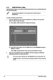
Download the latest BIOS file for this motherboard from the ASUS website at www.asus.com. Go to the Tools menu to select EZ Flash 2 and press to switch between drives until the correct BIOS file is found. 2. Press to enable it. 2.1.2 ASUS EZ Flash 2 utility ASUS EZ Flash 2 allows you to update the BIOS without... 32/16 format and single partition only. • DO NOT shut down or reset the system while updating the BIOS to prevent system boot failure! 2-2 ASUS P5KPL-AM SE To update the BIOS using EZ Flash 2. 1.
Download the latest BIOS file for this motherboard from the ASUS website at www.asus.com. Go to the Tools menu to select EZ Flash 2 and press to switch between drives until the correct BIOS file is found. 2. Press to enable it. 2.1.2 ASUS EZ Flash 2 utility ASUS EZ Flash 2 allows you to update the BIOS without... 32/16 format and single partition only. • DO NOT shut down or reset the system while updating the BIOS to prevent system boot failure! 2-2 ASUS P5KPL-AM SE To update the BIOS using EZ Flash 2. 1.
User Manual
Page 28
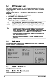
...select a field. See section 2.8 Exit menu. • The BIOS setup screens in this section are installing a motherboard, reconfiguring your screen. • Visit the ASUS website at www.asus.com to download the latest BIOS file for this utility. 2.2 BIOS setup program Use the BIOS Setup program when ...8226; Restart using this motherboard. 2.3 Main menu When you enter the BIOS Setup program, the Main menu screen appears, giving you want to enter Setup after changing any BIOS settings, load the default settings to set the system date. 2-4 ASUS P5KPL-AM SE They may not exactly ...
...select a field. See section 2.8 Exit menu. • The BIOS setup screens in this section are installing a motherboard, reconfiguring your screen. • Visit the ASUS website at www.asus.com to download the latest BIOS file for this utility. 2.2 BIOS setup program Use the BIOS Setup program when ...8226; Restart using this motherboard. 2.3 Main menu When you enter the BIOS Setup program, the Main menu screen appears, giving you want to enter Setup after changing any BIOS settings, load the default settings to set the system date. 2-4 ASUS P5KPL-AM SE They may not exactly ...
User Manual
Page 30
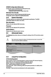
...-screen F1 General Help F10 Save and Exit ESC Exit Allows selection of the preset overclocking configuration options: Manual - loads overclocking profiles with spread spectrum. 2-6 ASUS P5KPL-AM SE Test Mode - The BIOS automatically detects the items in this menu. ATA/IDE Configuration [Enhanced] Configuration options: [Disabled] [Compatible] [Enhanced] Enhanced Mode Support On...
...-screen F1 General Help F10 Save and Exit ESC Exit Allows selection of the preset overclocking configuration options: Manual - loads overclocking profiles with spread spectrum. 2-6 ASUS P5KPL-AM SE Test Mode - The BIOS automatically detects the items in this menu. ATA/IDE Configuration [Enhanced] Configuration options: [Disabled] [Compatible] [Enhanced] Enhanced Mode Support On...
User Manual
Page 32
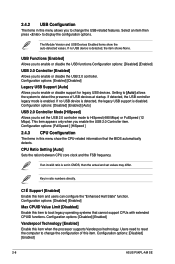
... directly. Configuration options: [Disabled] [Enabled] Vanderpool Technology [Enabled] Enable this item and users can configure the "Enhanced Halt State" function. Configuration options: [Disabled] [Enabled] 2-8 ASUS P5KPL-AM SE If no USB device is disabled. Configuration options: [Disabled] [Enabled] [Auto] USB 2.0 Controller Mode [HiSpeed] Allows you enable the USB 2.0 Controller item. C1É Support...
... directly. Configuration options: [Disabled] [Enabled] Vanderpool Technology [Enabled] Enable this item and users can configure the "Enhanced Halt State" function. Configuration options: [Disabled] [Enabled] 2-8 ASUS P5KPL-AM SE If no USB device is disabled. Configuration options: [Disabled] [Enabled] [Auto] USB 2.0 Controller Mode [HiSpeed] Allows you enable the USB 2.0 Controller item. C1É Support...


