
P5GD1-VM User's manual English Edition E1881
Page 3
... vii P5GD1-VM specifications summary viii Chapter 1: Product introduction 1.1 Welcome 1-2 1.2 Package contents 1-2 1.3 Special features 1-2 1.3.1 Product highlights 1-2 1.3.2 Innovative ASUS features 1-4 1.4 Before you proceed 1-5 1.5 Motherboard overview 1-6 1.5.1 Motherboard layout 1-6 1.5.2 Placement direction 1-7 1.5.3 Screw holes 1-7 1.6 Central Processing Unit (CPU 1-8 1.6.1 Installing the CPU 1-8 1.6.2 Installing the CPU heatsink and fan 1-11 1.6.3 Uninstalling the CPU heatsink and fan 1-13 1.7 System memory 1-15...
... vii P5GD1-VM specifications summary viii Chapter 1: Product introduction 1.1 Welcome 1-2 1.2 Package contents 1-2 1.3 Special features 1-2 1.3.1 Product highlights 1-2 1.3.2 Innovative ASUS features 1-4 1.4 Before you proceed 1-5 1.5 Motherboard overview 1-6 1.5.1 Motherboard layout 1-6 1.5.2 Placement direction 1-7 1.5.3 Screw holes 1-7 1.6 Central Processing Unit (CPU 1-8 1.6.1 Installing the CPU 1-8 1.6.2 Installing the CPU heatsink and fan 1-11 1.6.3 Uninstalling the CPU heatsink and fan 1-13 1.7 System memory 1-15...
P5GD1-VM User's manual English Edition E1881
Page 12
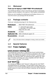
... Technology and is damaged or missing, contact your computer to run on it another standout in the long line of system memory for faster and more efficient computing. Intel® EM64T The motherboard supports Intel® Pentium® 4 CPUs with a...it , check the items in the 775-land package. See page 1-8 for the following items. Motherboard ASUS P5GD1-VM motherboard Cables 2 x Serial ATA signal cables 1 x Ultra DMA 133/100/66 cable Floppy disk drive cable Accessories I/O shield A p p l i c a t i o n C D s ASUS motherboard support CD D o c u m e n t a t i o n User guide ...
... Technology and is damaged or missing, contact your computer to run on it another standout in the long line of system memory for faster and more efficient computing. Intel® EM64T The motherboard supports Intel® Pentium® 4 CPUs with a...it , check the items in the 775-land package. See page 1-8 for the following items. Motherboard ASUS P5GD1-VM motherboard Cables 2 x Serial ATA signal cables 1 x Ultra DMA 133/100/66 cable Floppy disk drive cable Accessories I/O shield A p p l i c a t i o n C D s ASUS motherboard support CD D o c u m e n t a t i o n User guide ...
P5GD1-VM User's manual English Edition E1881
Page 13
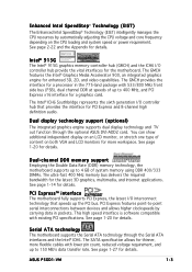
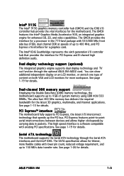
...function through the Serial ATA interfaces and the Intel® ICH6. See page 1-14 for details. See page 1-27 for details. ASUS P5GD1-VM 1-3 PCI Express features point-to-point serial interconnections between devices and allows higher clockspeeds by automatically adjusting the CPU voltage and core ...SATA specification allows for thinner, more workspace. See page 2-22 and the Appendix for details. Intel® 915G The Intel® 915G graphics memory controller hub (GMCH) and the ICH6 I /O controller hub that speeds up to 400 MHz, and PCI Express x16 interface for a processor ...
...function through the Serial ATA interfaces and the Intel® ICH6. See page 1-14 for details. See page 1-27 for details. ASUS P5GD1-VM 1-3 PCI Express features point-to-point serial interconnections between devices and allows higher clockspeeds by automatically adjusting the CPU voltage and core ...SATA specification allows for thinner, more workspace. See page 2-22 and the Appendix for details. Intel® 915G The Intel® 915G graphics memory controller hub (GMCH) and the ICH6 I /O controller hub that speeds up to 400 MHz, and PCI Express x16 interface for a processor ...

P5GD1-VM User's manual English Edition E1881
Page 20
Close the load plate (A), then A push the load lever (B) until it snaps into the socket to the Appendix for more information on the socket and damaging the CPU! 6. B The motherboard supports Intel® Pentium® 4 LGA775 processors with the Intel® Enhanced Memory 64 Technology (EM64T), Enhanced Intel SpeedStep® Technology (EIST), and Hyper-Threading Technology. Refer to prevent bending the connectors on these CPU features. 1-10 Chapter 1: Product introduction DO NOT force the CPU into the retention tab. The CPU fits in only one correct orientation.
Close the load plate (A), then A push the load lever (B) until it snaps into the socket to the Appendix for more information on the socket and damaging the CPU! 6. B The motherboard supports Intel® Pentium® 4 LGA775 processors with the Intel® Enhanced Memory 64 Technology (EM64T), Enhanced Intel SpeedStep® Technology (EIST), and Hyper-Threading Technology. Refer to prevent bending the connectors on these CPU features. 1-10 Chapter 1: Product introduction DO NOT force the CPU into the retention tab. The CPU fits in only one correct orientation.
P5GD1-VM User's manual English Edition E1881
Page 25
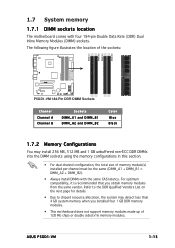
...unbuffered non-ECC DDR DIMMs into the DIMM sockets using the memory configurations in this section. • For dual-channel configuration, the total size of 128 Mb chips or double sided x16 memory modules. ASUS P5GD1-VM 1-15 For optimum compatibility, it is recommended that you installed... four 1 GB DDR memory modules. • This motherboard does not support memory modules made up of memory module(s) installed per channel must be the same (...
...unbuffered non-ECC DDR DIMMs into the DIMM sockets using the memory configurations in this section. • For dual-channel configuration, the total size of 128 Mb chips or double sided x16 memory modules. ASUS P5GD1-VM 1-15 For optimum compatibility, it is recommended that you installed... four 1 GB DDR memory modules. • This motherboard does not support memory modules made up of memory module(s) installed per channel must be the same (...

P5GD1-VM User's manual English Edition E1881
Page 26
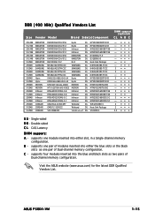
.... supports one module inserted into the blue and black slots as one pair of Dual-channel memory configuration. Visit the ASUS website (www.asus.com) for the latest DDR Qualified Vendors List. 1-16 Chapter 1: Product introduction DDR (400 MHz) Qualified Vendors List Size Vendor Model Brand Side(s)Component 256 ...; S S - supports four modules inserted into either the blue slots or the black slots as two pairs of modules inserted into either slot, in a Single-channel memory configuration. B - Double-sided C L- Single-sided D S -
.... supports one module inserted into the blue and black slots as one pair of Dual-channel memory configuration. Visit the ASUS website (www.asus.com) for the latest DDR Qualified Vendors List. 1-16 Chapter 1: Product introduction DDR (400 MHz) Qualified Vendors List Size Vendor Model Brand Side(s)Component 256 ...; S S - supports four modules inserted into either the blue slots or the black slots as two pairs of modules inserted into either slot, in a Single-channel memory configuration. B - Double-sided C L- Single-sided D S -

P5GD1-VM User's manual English Edition E1881
Page 31
..., never remove the cap on pins 2-3 for about 5~10 seconds, then move the cap back to re-enter data. You can clear the CMOS memory of date, time, and system setup parameters by erasing the CMOS RTC RAM data. Reinstall the battery. 5. Turn OFF the computer and unplug the ... jumper cap from pins 1-2 (default) to clear the Real Time Clock (RTC) RAM in CMOS, which include system setup information such as system passwords. P5GD1-VM ® P5GD1-VM Clear RTC RAM CLRTC1 12 23 Normal (Default) Clear CMOS ASUS P5GD1-VM 1-21 Clear RTC RAM (CLRTC1) This jumper allows you to pins 2-3.
..., never remove the cap on pins 2-3 for about 5~10 seconds, then move the cap back to re-enter data. You can clear the CMOS memory of date, time, and system setup parameters by erasing the CMOS RTC RAM data. Reinstall the battery. 5. Turn OFF the computer and unplug the ... jumper cap from pins 1-2 (default) to clear the Real Time Clock (RTC) RAM in CMOS, which include system setup information such as system passwords. P5GD1-VM ® P5GD1-VM Clear RTC RAM CLRTC1 12 23 Normal (Default) Clear CMOS ASUS P5GD1-VM 1-21 Clear RTC RAM (CLRTC1) This jumper allows you to pins 2-3.
P5GD1-VM User's manual English Edition E1881
Page 40
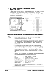
...of a 20-pin PSU. • The ATX 12 V 350 W Spec. 2.0 PSU passed the motherboard power requirement test with the following configuration: CPU : Memory : Grpahics card : Parallel ATA devices : Serial ATA device : Optical drives : Intel® Pentium® 4 3.6 GHz 512 MB DDR2 (x 4) PCI Express... 4-pin ATX +12 V power plug; Find the proper orientation and push down firmly until the connectors completely fit. ATX12V1 EATXPWR1 P5GD1-VM GND +12V DC ® P5GD1-VM ATX power connectors GND +3 Volts +12V DC +12 Volts +12 Volts +5V Standby Power OK Ground +5 Volts Ground +5 ...
...of a 20-pin PSU. • The ATX 12 V 350 W Spec. 2.0 PSU passed the motherboard power requirement test with the following configuration: CPU : Memory : Grpahics card : Parallel ATA devices : Serial ATA device : Optical drives : Intel® Pentium® 4 3.6 GHz 512 MB DDR2 (x 4) PCI Express... 4-pin ATX +12 V power plug; Find the proper orientation and push down firmly until the connectors completely fit. ATX12V1 EATXPWR1 P5GD1-VM GND +12V DC ® P5GD1-VM ATX power connectors GND +3 Volts +12V DC +12 Volts +12 Volts +5V Standby Power OK Ground +5 Volts Ground +5 ...
P5GD1-VM User's manual English Edition E1881
Page 62
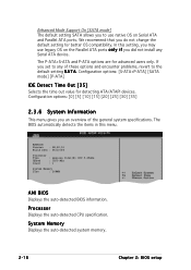
If you set to any Serial ATA device. System Memory Displays the auto-detected system memory. 2-18 Chapter 2: BIOS setup Enhanced Mode Support On [SATA mode] The default setting SATA allows you to the default setting S A T A. Configuration options: [S-ATA+P-...ATA ports. AMIBIOS Version : 08.00.10 Build Date : 06/10/04 Processor Type Speed Count : Genuine Intel(R) CPU 3.20GHz : 3200 MHz : 1 System Memory Size : 248MB AMI BIOS Displays the auto-detected BIOS information. Processor Displays the auto-detected CPU specification. The BIOS automatically detects the items in this...
If you set to any Serial ATA device. System Memory Displays the auto-detected system memory. 2-18 Chapter 2: BIOS setup Enhanced Mode Support On [SATA mode] The default setting SATA allows you to the default setting S A T A. Configuration options: [S-ATA+P-...ATA ports. AMIBIOS Version : 08.00.10 Build Date : 06/10/04 Processor Type Speed Count : Genuine Intel(R) CPU 3.20GHz : 3200 MHz : 1 System Memory Size : 248MB AMI BIOS Displays the auto-detected BIOS information. Processor Displays the auto-detected CPU specification. The BIOS automatically detects the items in this...

P5GD1-VM User's manual English Edition E1881
Page 66
... to display the sub-menu. Advanced Chipset Settings Configure DRAM Timing by SPD Enabled] Booting Graphic Adapter Priority Internal Graphics Mode Select Fixed Graphic Memory Size DVMT Graphic Memory Size Boot Display Device Flat Panel Type Local Flat Panel Scaling TV Connector HDTV Output TV Standard [PCI Express/Int-VGA] [Enabled, 8M...
... to display the sub-menu. Advanced Chipset Settings Configure DRAM Timing by SPD Enabled] Booting Graphic Adapter Priority Internal Graphics Mode Select Fixed Graphic Memory Size DVMT Graphic Memory Size Boot Display Device Flat Panel Type Local Flat Panel Scaling TV Connector HDTV Output TV Standard [PCI Express/Int-VGA] [Enabled, 8M...

P5GD1-VM User's manual English Edition E1881
Page 67
...RAS# Activate to the DDR SDRAM. Configuration options: [4] [8] Booting Graphic Adapter Priority [PCI/PCI Express] Allows selection of system memory pre-allocated by SPD [Enabled] When this item is enabled, the DRAM timing parameters are set the DRAM timing parameters through the... RAS# to CAS# Delay [4 Clocks] Controls the latency between the SDRAM read /write command. Configuration options: [Disabled] [Disabled] ASUS P5GD1-VM 2-23 When disabled, you can manually set according to use as primary boot device. Advanced Chipset Settings Configure DRAM Timing by the internal...
...RAS# Activate to the DDR SDRAM. Configuration options: [4] [8] Booting Graphic Adapter Priority [PCI/PCI Express] Allows selection of system memory pre-allocated by SPD [Enabled] When this item is enabled, the DRAM timing parameters are set the DRAM timing parameters through the... RAS# to CAS# Delay [4 Clocks] Controls the latency between the SDRAM read /write command. Configuration options: [Disabled] [Disabled] ASUS P5GD1-VM 2-23 When disabled, you can manually set according to use as primary boot device. Advanced Chipset Settings Configure DRAM Timing by the internal...

P5GD1-VM User's manual English Edition E1881
Page 69
... only when the P a r a l l e l P o r t M o d e is available to be used by Legacy ISA devices. ASUS P5GD1-VM 2-25 This item allows you to select the Parallel Port base addresses. Advanced PCI/PnP Settings WARNING: Setting wrong values in below sections may cause ... reserved for PCI/PnP devices. The menu includes setting IRQ and DMA channel resources for either PCI/PnP or legacy ISA devices, and setting the memory size block for legacy ISA devices. Configuration options: [Disabled] [378] [278] [3BC] Parallel Port Mode [ECP] Allows you to malfunction. Configuration options: [1.9] ...
... only when the P a r a l l e l P o r t M o d e is available to be used by Legacy ISA devices. ASUS P5GD1-VM 2-25 This item allows you to select the Parallel Port base addresses. Advanced PCI/PnP Settings WARNING: Setting wrong values in below sections may cause ... reserved for PCI/PnP devices. The menu includes setting IRQ and DMA channel resources for either PCI/PnP or legacy ISA devices, and setting the memory size block for legacy ISA devices. Configuration options: [Disabled] [378] [278] [3BC] Parallel Port Mode [ECP] Allows you to malfunction. Configuration options: [1.9] ...
P5GD1-VM User's manual English Edition E1671
Page 3
... 1-vii Operation safety 1-vii P5GD1-VM specifications summary 1-viii Chapter 1: Product introduction 1.1 Welcome 1-2 1.2 Package contents 1-2 1.3 Special features 1-2 1.3.1 Product highlights 1-2 1.3.2 Innovative ASUS features 1-4 1.4 Before you proceed 1-5 1.5 Motherboard overview 1-6 1.5.1 Motherboard layout 1-6 1.5.2 Placement direction 1-7 1.5.3 Screw holes 1-7 16.1 Installling the CPU 1-8 1.6 Central Processing Unit (CPU 1-8 1.6.2 Installling the CPU heatsink and fan 1-11 1.7 System memory 1-13 1.7.1 DIMM sockets location...
... 1-vii Operation safety 1-vii P5GD1-VM specifications summary 1-viii Chapter 1: Product introduction 1.1 Welcome 1-2 1.2 Package contents 1-2 1.3 Special features 1-2 1.3.1 Product highlights 1-2 1.3.2 Innovative ASUS features 1-4 1.4 Before you proceed 1-5 1.5 Motherboard overview 1-6 1.5.1 Motherboard layout 1-6 1.5.2 Placement direction 1-7 1.5.3 Screw holes 1-7 16.1 Installling the CPU 1-8 1.6 Central Processing Unit (CPU 1-8 1.6.2 Installling the CPU heatsink and fan 1-11 1.7 System memory 1-13 1.7.1 DIMM sockets location...
P5GD1-VM User's manual English Edition E1671
Page 13
... a processor in packets. Serial ATA technology The motherboard supports the Serial ATA technology through the optional ASUS DVI-ADD2 card. ASUS P5GD1-VM 1-3 Dual display technology support (optional) The integrated graphics engine supports dual display technology and TV out... function through the Serial ATA interfaces and the Intel® ICH6. The SATA specification allows for the motherboard. Intel® 915G The Intel® 915G graphics memory...
... a processor in packets. Serial ATA technology The motherboard supports the Serial ATA technology through the optional ASUS DVI-ADD2 card. ASUS P5GD1-VM 1-3 Dual display technology support (optional) The integrated graphics engine supports dual display technology and TV out... function through the Serial ATA interfaces and the Intel® ICH6. The SATA specification allows for the motherboard. Intel® 915G The Intel® 915G graphics memory...

P5GD1-VM User's manual English Edition E1671
Page 23
... A Channel B Sockets DIMM_A1 and DIMM_B1 DIMM_A2 and DIMM_B2 Color Blue Black ASUS P5GD1-VM 1-13 CPU_FAN1 ® Do not forget to the connector on the motherboard labeled CPU_FAN. Hardware monitoring errors can occur if you fail to plug this connector. 1.7 System memory 1.7.1 DIMM sockets location The motherboard comes with four 184-pin Double Data...
... A Channel B Sockets DIMM_A1 and DIMM_B1 DIMM_A2 and DIMM_B2 Color Blue Black ASUS P5GD1-VM 1-13 CPU_FAN1 ® Do not forget to the connector on the motherboard labeled CPU_FAN. Hardware monitoring errors can occur if you fail to plug this connector. 1.7 System memory 1.7.1 DIMM sockets location The motherboard comes with four 184-pin Double Data...

P5GD1-VM User's manual English Edition E1671
Page 24
For optimum compatibility, it is recommended that you installed four 1 GB DDR memory modules. • This motherboard does not support memory modules made up of memory module(s) installed per channel must be the same (DIMM_A1 + DIMM_B1 = DIMM_A2 + DIMM_B2). • Always install DIMMs with the same CAS latency. Refer to ...chipset resource allocation, the system may install 256 MB, 512 MB and 1 GB unbuffered non-ECC DDR DIMMs into the DIMM sockets using the memory configurations in this section. • For dual-channel configuration, the total size of 128 Mb chips or double sided x16...
For optimum compatibility, it is recommended that you installed four 1 GB DDR memory modules. • This motherboard does not support memory modules made up of memory module(s) installed per channel must be the same (DIMM_A1 + DIMM_B1 = DIMM_A2 + DIMM_B2). • Always install DIMMs with the same CAS latency. Refer to ...chipset resource allocation, the system may install 256 MB, 512 MB and 1 GB unbuffered non-ECC DDR DIMMs into the DIMM sockets using the memory configurations in this section. • For dual-channel configuration, the total size of 128 Mb chips or double sided x16...
P5GD1-VM User's manual English Edition E1671
Page 25
... inserted into either the blue slots or the black slots as two pairs of modules inserted into either slot, in a Single-channel memory configuration. DDR (400 MHz) Qualified Vendors List Size Vendor Model Brand Side(s)Component 256 MB 512 MB 256 MB 512 MB 256 ...-5 DIMM support (optional) CL A B C 3 •• 3 3 3 •• • 3 •• 3 2 •• • 2 •• • 2.5 • • • S S - ASUS P5GD1-VM 1-15 Visit the ASUS website (www.asus.com) for the latest DDR Qualified Vendors List. CAS Latency DIMM support: A - B -
... inserted into either the blue slots or the black slots as two pairs of modules inserted into either slot, in a Single-channel memory configuration. DDR (400 MHz) Qualified Vendors List Size Vendor Model Brand Side(s)Component 256 MB 512 MB 256 MB 512 MB 256 ...-5 DIMM support (optional) CL A B C 3 •• 3 3 3 •• • 3 •• 3 2 •• • 2 •• • 2.5 • • • S S - ASUS P5GD1-VM 1-15 Visit the ASUS website (www.asus.com) for the latest DDR Qualified Vendors List. CAS Latency DIMM support: A - B -

P5GD1-VM User's manual English Edition E1671
Page 30
You can clear the CMOS memory of date, time, and system setup parameters by erasing the CMOS RTC RAM data. Turn OFF the computer and unplug the power cord. 2. 1.9 Jumpers 1. Re-... the Real Time Clock (RTC) RAM in CMOS, which include system setup information such as system passwords. Removing the cap will cause system boot failure! P5GD1-VM ® P5GD1-VM Clear RTC RAM CLRTC1 12 23 Normal (Default) Clear CMOS 1-20 Chapter 1: Product introduction The onboard button cell battery powers the RAM data in...
You can clear the CMOS memory of date, time, and system setup parameters by erasing the CMOS RTC RAM data. Turn OFF the computer and unplug the power cord. 2. 1.9 Jumpers 1. Re-... the Real Time Clock (RTC) RAM in CMOS, which include system setup information such as system passwords. Removing the cap will cause system boot failure! P5GD1-VM ® P5GD1-VM Clear RTC RAM CLRTC1 12 23 Normal (Default) Clear CMOS 1-20 Chapter 1: Product introduction The onboard button cell battery powers the RAM data in...

P5GD1-VM User's manual English Edition E1671
Page 39
...on +12 V and that you use a PSU with a minimum 350 W power rating. We do not, however, recommend the use of 350 W. ASUS P5GD1-VM 1-29 This PSU type has a 24-pin and 4-pin ATX power plugs. • If you intend to fit these connectors in only one orientation....power rating of a 20-pin PSU. • The ATX 12 V 350 W Spec. 2.0 PSU passed the motherboard power requirement test with the following configuration: CPU : Memory : Grpahics card : Parallel ATA devices : Serial ATA device : Optical drives : Intel® Pentium® 4 3.6 GHz 512 MB DDR2 (x 4) PCI Express x16 ...
...on +12 V and that you use a PSU with a minimum 350 W power rating. We do not, however, recommend the use of 350 W. ASUS P5GD1-VM 1-29 This PSU type has a 24-pin and 4-pin ATX power plugs. • If you intend to fit these connectors in only one orientation....power rating of a 20-pin PSU. • The ATX 12 V 350 W Spec. 2.0 PSU passed the motherboard power requirement test with the following configuration: CPU : Memory : Grpahics card : Parallel ATA devices : Serial ATA device : Optical drives : Intel® Pentium® 4 3.6 GHz 512 MB DDR2 (x 4) PCI Express x16 ...

P5GD1-VM User's manual English Edition E1671
Page 62
...device. AMIBIOS Version : 08.00.10 Build Date : 06/10/04 Processor Type : Genuine Intel(R) CPU 3.20GHz Speed : 3200 MHz Count : 1 System Memory Size : 248MB AMI BIOS Displays the auto-detected BIOS information Processor Displays the auto-detected CPU specification System... Memory Displays the auto-detected system memory 2-18 Chapter 2: BIOS setup Configuration options: [S-ATA+P-ATA] [SATA mode] [P-ATA] IDE Detect Time Out [35] Selects the time out value for ...
...device. AMIBIOS Version : 08.00.10 Build Date : 06/10/04 Processor Type : Genuine Intel(R) CPU 3.20GHz Speed : 3200 MHz Count : 1 System Memory Size : 248MB AMI BIOS Displays the auto-detected BIOS information Processor Displays the auto-detected CPU specification System... Memory Displays the auto-detected system memory 2-18 Chapter 2: BIOS setup Configuration options: [S-ATA+P-ATA] [SATA mode] [P-ATA] IDE Detect Time Out [35] Selects the time out value for ...


