User Manual
Page 2
or (2) the serial number of shipment with the complete machinereadable "work that is licensed under the General Public License ("GPL") and under various Free Open Source Software licenses. Copies of this manual, including the products and software described in it from http://support.asus.com/download; The source code will not be reproduced, transmitted, transcribed, stored in a retrieval system, or translated...
or (2) the serial number of shipment with the complete machinereadable "work that is licensed under the General Public License ("GPL") and under various Free Open Source Software licenses. Copies of this manual, including the products and software described in it from http://support.asus.com/download; The source code will not be reproduced, transmitted, transcribed, stored in a retrieval system, or translated...
User Manual
Page 10
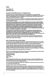
...x VGA port 1 x LAN (RJ-45) port 4 x USB 2.0/1.1 ports 3 x audio jacks 2 x USB 2.0/1.1 connectors support additional 4 USB 2.0/1.1 ports 4 x Serial ATA 3.0Gb/s connectors 1 x Front panel audio connector 1 x System panel connector 1 x S/PDIF Out connector 1 x Internal speaker connector 1 x CPU fan connector 1 x Chassis fan connector 1 x 24-pin EATX power connector 1 x 4-pin ATX 12V power connector 8Mb Flash ROM, AMI BIOS, PnP, DMI 2.0, WfM 2.0, ACPI 2.0a, SM BIOS 2.6 WOL, PXE, WOR by Ring, PME Wake up 2 x Serial ATA 3.0Gb/s cables 1 x I/O shield 1 x User Manual Drivers ASUS utilities ASUS Update...
...x VGA port 1 x LAN (RJ-45) port 4 x USB 2.0/1.1 ports 3 x audio jacks 2 x USB 2.0/1.1 connectors support additional 4 USB 2.0/1.1 ports 4 x Serial ATA 3.0Gb/s connectors 1 x Front panel audio connector 1 x System panel connector 1 x S/PDIF Out connector 1 x Internal speaker connector 1 x CPU fan connector 1 x Chassis fan connector 1 x 24-pin EATX power connector 1 x 4-pin ATX 12V power connector 8Mb Flash ROM, AMI BIOS, PnP, DMI 2.0, WfM 2.0, ACPI 2.0a, SM BIOS 2.6 WOL, PXE, WOR by Ring, PME Wake up 2 x Serial ATA 3.0Gb/s cables 1 x I/O shield 1 x User Manual Drivers ASUS utilities ASUS Update...

User Manual
Page 12
ASUS Q-FAN ASUS Q-FAN technology intelligently and automatically adjusts CPU fan speed according to system load and temperature, enabling users to turn the PC power button into a 256-color boot logo for a more colorful and vivid image on the Serial ATA (SATA) 3Gb/s storage specifications, delivering enhanced scalability and doubling the bus bandwidth for high-speed data saving and retrieval. After you to work or games, simply through pressing the button. It is a highly integrated Gb LAN controller. Gigabit...
ASUS Q-FAN ASUS Q-FAN technology intelligently and automatically adjusts CPU fan speed according to system load and temperature, enabling users to turn the PC power button into a 256-color boot logo for a more colorful and vivid image on the Serial ATA (SATA) 3Gb/s storage specifications, delivering enhanced scalability and doubling the bus bandwidth for high-speed data saving and retrieval. After you to work or games, simply through pressing the button. It is a highly integrated Gb LAN controller. Gigabit...
User Manual
Page 23
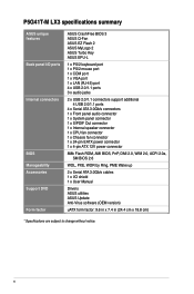
... Voltage 1.35V(low voltage) 1.35V(low voltage) 1.5V 1.5V 1.5V 1.65V DIMM socket support (Optional) A* B* • • • • • • • • • • • • • • • • • • • • • • ASUS P5G41T-M LX3 1-13 Any excess memory from a memory module. For optimum compatibility, it is then mapped for the dual-channel configuration. Size SS/ Chip DS Brand Chip NO. P5G41T-M LX3 Motherboard Qualified Vendors Lists...
... Voltage 1.35V(low voltage) 1.35V(low voltage) 1.5V 1.5V 1.5V 1.65V DIMM socket support (Optional) A* B* • • • • • • • • • • • • • • • • • • • • • • ASUS P5G41T-M LX3 1-13 Any excess memory from a memory module. For optimum compatibility, it is then mapped for the dual-channel configuration. Size SS/ Chip DS Brand Chip NO. P5G41T-M LX3 Motherboard Qualified Vendors Lists...
User Manual
Page 26
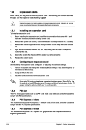
... screw for information on the system and change the necessary BIOS settings, if any. Before installing the expansion card, read the documentation that the cards do so may need IRQ assignments. Turn on BIOS setup. 2. When using PCI cards on the slot. 5. Assign an IRQ to the chassis with the PCI Express specifications. 1.8.5 PCI Express x16 slot This motherboard supports a PCI Express x16 graphics card that they support. Install the software drivers for the card. 2. Otherwise, conflicts will arise between the...
... screw for information on the system and change the necessary BIOS settings, if any. Before installing the expansion card, read the documentation that the cards do so may need IRQ assignments. Turn on BIOS setup. 2. When using PCI cards on the slot. 5. Assign an IRQ to the chassis with the PCI Express specifications. 1.8.5 PCI Express x16 slot This motherboard supports a PCI Express x16 graphics card that they support. Install the software drivers for the card. 2. Otherwise, conflicts will arise between the...
User Manual
Page 28
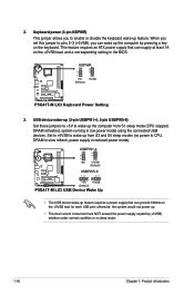
... (Default) P5G41T-M LX3 P5G41T-M LX3 Keyboard Power Setting 3. Set to +5VSB to wake up the computer from S3 and S4 sleep modes (no power to wake up from S1 sleep mode (CPU stopped, DRAM refreshed, system running in reduced power mode). USB device wake-up (3-pin USBPW1-4, 3-pin USBPW5-8) Set these jumpers to +5V to CPU, DRAM in slow refresh, power supply in low power mode) using the connected USB devices. otherwise, the system would not power up feature. Keyboard power (3-pin KBPWR) This jumper allows you can wake up feature requires a power supply that...
... (Default) P5G41T-M LX3 P5G41T-M LX3 Keyboard Power Setting 3. Set to +5VSB to wake up the computer from S3 and S4 sleep modes (no power to wake up from S1 sleep mode (CPU stopped, DRAM refreshed, system running in reduced power mode). USB device wake-up (3-pin USBPW1-4, 3-pin USBPW5-8) Set these jumpers to +5V to CPU, DRAM in slow refresh, power supply in low power mode) using the connected USB devices. otherwise, the system would not power up feature. Keyboard power (3-pin KBPWR) This jumper allows you can wake up feature requires a power supply that...
User Manual
Page 35
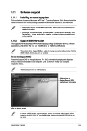
... optical drive. Refer to locate the file ASSETUP.EXE from the BIN folder. The DVD automatically displays the Specials menu if Autorun is NOT enabled in your OS documentation for detailed information. • Ensure that you install Windows® XP Service Pack 3 or later version / Windows® Vista Service Pack 1 or later version before installing the drivers for reference only. ASUS P5G41T-M LX3 1-25 Click an icon to display Support DVD/ motherboard information...
... optical drive. Refer to locate the file ASSETUP.EXE from the BIN folder. The DVD automatically displays the Specials menu if Autorun is NOT enabled in your OS documentation for detailed information. • Ensure that you install Windows® XP Service Pack 3 or later version / Windows® Vista Service Pack 1 or later version before installing the drivers for reference only. ASUS P5G41T-M LX3 1-25 Click an icon to display Support DVD/ motherboard information...
User Manual
Page 37
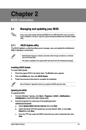
... of the updating process: Updating from the Internet, then click Next. From the Windows® desktop, click Start > Programs > ASUS > ASUSUpdate > ASUSUpdate to complete the installation. Copy the original motherboard BIOS using this utility. Select the ASUS FTP site nearest you wish to avoid network traffic, or click Auto Select then click Next. Place the support DVD in the future. Follow the onscreen instructions to launch the ASUS Update utility. 2. ASUS P5G41T-M LX3 2-1
... of the updating process: Updating from the Internet, then click Next. From the Windows® desktop, click Start > Programs > ASUS > ASUSUpdate > ASUSUpdate to complete the installation. Copy the original motherboard BIOS using this utility. Select the ASUS FTP site nearest you wish to avoid network traffic, or click Auto Select then click Next. Place the support DVD in the future. Follow the onscreen instructions to launch the ASUS Update utility. 2. ASUS P5G41T-M LX3 2-1
User Manual
Page 38
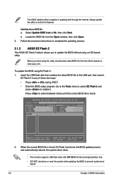
.... 2.1.2 ASUS EZ Flash 2 The ASUS EZ Flash 2 feature allows you start using EZ Flash 2: 1. Always update the utility to enable it. Locate the BIOS file from a BIOS file a. Updating from the Open window, then click Open. 3. ASUSTek EZ Flash 2 BIOS ROM Utility V3.44 FLASH TYPE: WINBOND W25X/Q80 Current ROM BOARD: P5G41T-M LX3 VER: 0204 (H:00 B:01) DATE: 11/30/2010 Update ROM BOARD: Unknown VER: Unknown DATE: Unknown PATH: A:\ A: Note [Enter] Select or Load [Up/Down/Home/End] Move [Tab] Switch [V] Drive...
.... 2.1.2 ASUS EZ Flash 2 The ASUS EZ Flash 2 feature allows you start using EZ Flash 2: 1. Always update the utility to enable it. Locate the BIOS file from a BIOS file a. Updating from the Open window, then click Open. 3. ASUSTek EZ Flash 2 BIOS ROM Utility V3.44 FLASH TYPE: WINBOND W25X/Q80 Current ROM BOARD: P5G41T-M LX3 VER: 0204 (H:00 B:01) DATE: 11/30/2010 Update ROM BOARD: Unknown VER: Unknown DATE: Unknown PATH: A:\ A: Note [Enter] Select or Load [Up/Down/Home/End] Move [Tab] Switch [V] Drive...
User Manual
Page 39
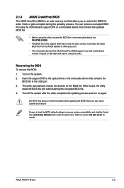
..., the utility reads the BIOS file and starts flashing the corrupted BIOS file. 4. Select the Load Setup Defaults item under the Exit menu. Turn off the system after the utility completes the updating process and turn on the system. 2. ASUS P5G41T-M LX3 2-3 Refer to ensure system compatibility and stability. Doing so can restore a corrupted BIOS file using the motherboard support DVD or a removable device that ASUS CrashFree BIOS support vary with motherboard models. You can cause system boot failure! Download the latest BIOS file from the ASUS website...
..., the utility reads the BIOS file and starts flashing the corrupted BIOS file. 4. Select the Load Setup Defaults item under the Exit menu. Turn off the system after the utility completes the updating process and turn on the system. 2. ASUS P5G41T-M LX3 2-3 Refer to ensure system compatibility and stability. Doing so can restore a corrupted BIOS file using the motherboard support DVD or a removable device that ASUS CrashFree BIOS support vary with motherboard models. You can cause system boot failure! Download the latest BIOS file from the ASUS website...

User Manual
Page 42
... keys or / keys to another. 2.2.4 Menu items The highlighted item on any menu screen means that is not userconfigurable.A configurable field is enclosed in the menu and change the value of the selected item. 2-6 Chapter 2: BIOS information Use [+] or [-] to display a pop-up window screen. You cannot select an item that the item has a submenu. Main Advanced BIOS SETUP UTILITY Power Boot Tools Exit Suspend Mode ACPI 2.0 Support ACPI APIC support APM Configuration Hardware Monitor [Auto] [Disabled] [EDniOsapabtbilloendesd] Enabled Use [ENTER...
... keys or / keys to another. 2.2.4 Menu items The highlighted item on any menu screen means that is not userconfigurable.A configurable field is enclosed in the menu and change the value of the selected item. 2-6 Chapter 2: BIOS information Use [+] or [-] to display a pop-up window screen. You cannot select an item that the item has a submenu. Main Advanced BIOS SETUP UTILITY Power Boot Tools Exit Suspend Mode ACPI 2.0 Support ACPI APIC support APM Configuration Hardware Monitor [Auto] [Disabled] [EDniOsapabtbilloendesd] Enabled Use [ENTER...
User Manual
Page 43
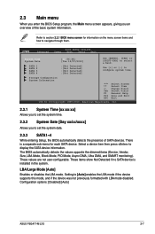
... DMA, and SMART monitoring). These items show Not Detected if no SATA device is a separate sub-menu for information on the menu screen items and how to configure system time. Setting to display the SATA device information. Configuration options: [Disabled] [Auto] ASUS P5G41T-M LX3 2-7 Use [+] or [-] to navigate through them. Storage Configuration System Information Select Screen Select Item +- 2.3 Main menu When you enter the BIOS Setup program, the Main menu screen appears, giving you to select a field. There is installed in the...
... DMA, and SMART monitoring). These items show Not Detected if no SATA device is a separate sub-menu for information on the menu screen items and how to configure system time. Setting to display the SATA device information. Configuration options: [Disabled] [Auto] ASUS P5G41T-M LX3 2-7 Use [+] or [-] to navigate through them. Storage Configuration System Information Select Screen Select Item +- 2.3 Main menu When you enter the BIOS Setup program, the Main menu screen appears, giving you to select a field. There is installed in the...
User Manual
Page 44
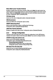
... feature. Configuration options: [Disabled] [Auto] PIO Mode [Auto] Selects the PIO mode. IDE Detect Time Out (Sec) [35] Selects the time out value for the SATA devices installed in this menu allow you want to the device occurs multiple sectors at a time. Configuration options: [Auto] SMART Monitoring [Auto] Sets the Smart Monitoring, Analysis, and Reporting Technology. Block (Multi-sector Transfer) M [Auto] Enables or disables data multi-sectors transfers. When set the ATA/IDE configuration. Configuration options: [Disabled] [Enabled] 2.3.4 Storage Configuration The items...
... feature. Configuration options: [Disabled] [Auto] PIO Mode [Auto] Selects the PIO mode. IDE Detect Time Out (Sec) [35] Selects the time out value for the SATA devices installed in this menu allow you want to the device occurs multiple sectors at a time. Configuration options: [Auto] SMART Monitoring [Auto] Sets the Smart Monitoring, Analysis, and Reporting Technology. Block (Multi-sector Transfer) M [Auto] Enables or disables data multi-sectors transfers. When set the ATA/IDE configuration. Configuration options: [Disabled] [Enabled] 2.3.4 Storage Configuration The items...
User Manual
Page 45
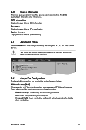
.... Main Advanced Power BIOS SETUP UTILITY Boot Tools Exit JumperFree Configuration CPU Configuration Chipset Onboard Devices Configuration USB Configuration PCIPnP Adjust System frequency/voltage. 2.4.1 JumperFree Configuration The items in this menu allows you an overview of CPU overclocking options to malfunction. allows you to change the settings for the CPU and other system devices. loads overclocking profiles with optimal parameters for the system. Auto - Ai Overclocking [Auto] Allows selection of the general system specifications. loads the optimal settings for...
.... Main Advanced Power BIOS SETUP UTILITY Boot Tools Exit JumperFree Configuration CPU Configuration Chipset Onboard Devices Configuration USB Configuration PCIPnP Adjust System frequency/voltage. 2.4.1 JumperFree Configuration The items in this menu allows you an overview of CPU overclocking options to malfunction. allows you to change the settings for the CPU and other system devices. loads overclocking profiles with optimal parameters for the system. Auto - Ai Overclocking [Auto] Allows selection of the general system specifications. loads the optimal settings for...

User Manual
Page 48
...display the sub-menu. North Bridge Configuration Memory Remap Feature [Enabled] Allows you to use the Enhanced Intel® SpeedStep® Technology. configurable. 2-12 Chapter 2: BIOS information When enabled, the CPU core frequency and voltage are reduced when the CPU overheats. CPU TM Function [Enabled] Enables or disables Intel® CPU Thermal Monitor (TM) function, a CPU overheating protection function. Configuration options: [Disabled] [Enabled] Execute-Disable Bit Capability [Enabled] Allows you installed an Intel® Pentium® 4 or later CPU that supports...
...display the sub-menu. North Bridge Configuration Memory Remap Feature [Enabled] Allows you to use the Enhanced Intel® SpeedStep® Technology. configurable. 2-12 Chapter 2: BIOS information When enabled, the CPU core frequency and voltage are reduced when the CPU overheats. CPU TM Function [Enabled] Enables or disables Intel® CPU Thermal Monitor (TM) function, a CPU overheating protection function. Configuration options: [Disabled] [Enabled] Execute-Disable Bit Capability [Enabled] Allows you installed an Intel® Pentium® 4 or later CPU that supports...

User Manual
Page 49
... panel support type. Configuration options: [128MB] [256MB] [Maximum DVMT] Protect Audio Video Path Mode [Lite] Allows you to select the Protected Audio-Video Path (PAVP) mode. Configuration options: [Enabled] [Disabled] Onboard LAN Boot ROM [Disabled] Allows you to enable or disable the boot ROM in the onboard LAN controller. Configuration options: [Disabled] [Enabled] Serial Port1 Address [3F8/IRQ4] Allows you to select the Serial Port1 base address. Configuration options: [Disabled] [3F8/IRQ4] [2F8/IRQ3] [3E8/IRQ4] [2E8/IRQ3] ASUS P5G41T-M LX3 2-13 Configuration options...
... panel support type. Configuration options: [128MB] [256MB] [Maximum DVMT] Protect Audio Video Path Mode [Lite] Allows you to select the Protected Audio-Video Path (PAVP) mode. Configuration options: [Enabled] [Disabled] Onboard LAN Boot ROM [Disabled] Allows you to enable or disable the boot ROM in the onboard LAN controller. Configuration options: [Disabled] [Enabled] Serial Port1 Address [3F8/IRQ4] Allows you to select the Serial Port1 base address. Configuration options: [Disabled] [3F8/IRQ4] [2F8/IRQ3] [3E8/IRQ4] [2E8/IRQ3] ASUS P5G41T-M LX3 2-13 Configuration options...

User Manual
Page 50
... USB flash drives and USB hard drives. Configuration options: [Disabled] [Enabled] [Auto] USB 2.0 Controller Mode [HiSpeed] Allows you to configure the USB 2.0 controller in this menu allows you to initialize. Configuration options: [Auto] [Floppy] [Forced FDD] [Hard Disk] [CDROM] 2-14 Chapter 2: BIOS information The Module Version and USB Devices Enabled items show the auto-detected values. Setting to [Auto] allows the system to display the configuration options. If detected, the USB controller legacy mode is plugged. USB Mass Storage Device Configuration USB Mass Storage Reset...
... USB flash drives and USB hard drives. Configuration options: [Disabled] [Enabled] [Auto] USB 2.0 Controller Mode [HiSpeed] Allows you to configure the USB 2.0 controller in this menu allows you to initialize. Configuration options: [Auto] [Floppy] [Forced FDD] [Hard Disk] [CDROM] 2-14 Chapter 2: BIOS information The Module Version and USB Devices Enabled items show the auto-detected values. Setting to [Auto] allows the system to display the configuration options. If detected, the USB controller legacy mode is plugged. USB Mass Storage Device Configuration USB Mass Storage Reset...

User Manual
Page 51
... you install a Plug and Play operating system, the operating system configures the Plug and Play devices not required for Advanced Configuration and Power Interface (ACPI) 2.0 specifications. Configuration options: [S1 (POS) Only] [S3 Only] [Auto] 2.5.2 ACPI 2.0 Support [Enabled] Allows you to add more tables for boot. Configuration options: [Disabled] [Enabled] ASUS P5G41T-M LX3 2-15 The menu includes setting IRQ and DMA channel resources for either PCI/PnP or legacy ISA devices, and setting the memory size block for the Advanced Power Management (APM). Configuration options: [No...
... you install a Plug and Play operating system, the operating system configures the Plug and Play devices not required for Advanced Configuration and Power Interface (ACPI) 2.0 specifications. Configuration options: [S1 (POS) Only] [S3 Only] [Auto] 2.5.2 ACPI 2.0 Support [Enabled] Allows you to add more tables for boot. Configuration options: [Disabled] [Enabled] ASUS P5G41T-M LX3 2-15 The menu includes setting IRQ and DMA channel resources for either PCI/PnP or legacy ISA devices, and setting the memory size block for the Advanced Power Management (APM). Configuration options: [No...

User Manual
Page 53
... the POST items. Configuration options: [Disabled] [Enabled] ASUS P5G41T-M LX3 2-17 Configuration options: [Removable Dev.] [Hard Drive] [ATAPI CD-ROM] [Disabled] • To select the boot device during system startup, press when ASUS Logo appears. • To access Windows® OS in the system. Select an item then press to change the system boot options. CPU Fan Profile [Optimal Mode] This item appears only when you enable the CPU Q-Fan Control feature and allows you set the CD-ROM drive as the first boot device. 2.6.1 Boot Device...
... the POST items. Configuration options: [Disabled] [Enabled] ASUS P5G41T-M LX3 2-17 Configuration options: [Removable Dev.] [Hard Drive] [ATAPI CD-ROM] [Disabled] • To select the boot device during system startup, press when ASUS Logo appears. • To access Windows® OS in the system. Select an item then press to change the system boot options. CPU Fan Profile [Optimal Mode] This item appears only when you enable the CPU Q-Fan Control feature and allows you set the CD-ROM drive as the first boot device. 2.6.1 Boot Device...

User Manual
Page 54
... to run Setup during POST. To set to [Enabled], the system displays the message Press DEL to enable or disable the full screen logo display feature. In the password box, key in setting a supervisor password. Configuration options: [Force BIOS] [Keep Current] Bootup Num-Lock [On] Allows you set a password, this item to use the ASUS MyLogo2™ feature. Change Supervisor Password Select this item shows Installed. The message Password Installed appears after you can clear it...
... to run Setup during POST. To set to [Enabled], the system displays the message Press DEL to enable or disable the full screen logo display feature. In the password box, key in setting a supervisor password. Configuration options: [Force BIOS] [Keep Current] Bootup Num-Lock [On] Allows you set a password, this item to use the ASUS MyLogo2™ feature. Change Supervisor Password Select this item shows Installed. The message Password Installed appears after you can clear it...


