User Manual
Page 3
... Memory configurations 1-4 1.5 Expansion slots 1-8 1.5.1 Installing an expansion card 1-8 1.5.2 Configuring an expansion card 1-8 1.5.3 PCI slot 1-8 1.5.4 PCI Express x1 slots 1-8 1.5.5 PCI Express x16 slot 1-8 1.6 Jumpers 1-9 1.7 Connectors 1-10 1.7.1 Rear panel connectors 1-10 1.7.2 Internal connectors 1-12 1.8 Software support 1-16 1.8.1 Installing an operating system 1-16 1.8.2 Support DVD information 1-16 Chapter 2: BIOS information 2.1 Managing and updating your BIOS 2-1 2.1.1 ASUS Update utility 2-1 2.1.2 ASUS EZ Flash 2 2-2 2.1.3 ASUS CrashFree BIOS 2-3 2.2 BIOS setup...
... Memory configurations 1-4 1.5 Expansion slots 1-8 1.5.1 Installing an expansion card 1-8 1.5.2 Configuring an expansion card 1-8 1.5.3 PCI slot 1-8 1.5.4 PCI Express x1 slots 1-8 1.5.5 PCI Express x16 slot 1-8 1.6 Jumpers 1-9 1.7 Connectors 1-10 1.7.1 Rear panel connectors 1-10 1.7.2 Internal connectors 1-12 1.8 Software support 1-16 1.8.1 Installing an operating system 1-16 1.8.2 Support DVD information 1-16 Chapter 2: BIOS information 2.1 Managing and updating your BIOS 2-1 2.1.1 ASUS Update utility 2-1 2.1.2 ASUS EZ Flash 2 2-2 2.1.3 ASUS CrashFree BIOS 2-3 2.2 BIOS setup...
User Manual
Page 8
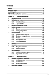
...-board, 4 ports at back panel) ASUS CrashFree BIOS 3 ASUS Q-Fan ASUS EZ Flash 2 ASUS MyLogo 2 ASUS AI NET 2 ASUS Turbo Key (continued on the next page) viii P5G41-M LX specifications summary CPU Chipset Front Side Bus Memory Graphics Expansion slots Storage LAN Audio USB ASUS special features LGA775 socket for Intel® Core™2 Quad / Core™2 Extreme / Core™2 Duo / Pentium® Dual-Core / Celeron® Dual-Core / Celeron® processors Supports Intel® 45nm multi-core CPU * Refer to www.asus.com for the Memory QVL (Qualified Vendors Lists...
...-board, 4 ports at back panel) ASUS CrashFree BIOS 3 ASUS Q-Fan ASUS EZ Flash 2 ASUS MyLogo 2 ASUS AI NET 2 ASUS Turbo Key (continued on the next page) viii P5G41-M LX specifications summary CPU Chipset Front Side Bus Memory Graphics Expansion slots Storage LAN Audio USB ASUS special features LGA775 socket for Intel® Core™2 Quad / Core™2 Extreme / Core™2 Duo / Pentium® Dual-Core / Celeron® Dual-Core / Celeron® processors Supports Intel® 45nm multi-core CPU * Refer to www.asus.com for the Memory QVL (Qualified Vendors Lists...
User Manual
Page 9
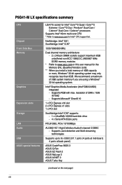
... keyboard port 1 x PS/2 mouse port 1 x COM port 1 x VGA port 1 x LAN (RJ-45) port 4 x USB 2.0/1.1 ports 6-channel audio I/O ports 2 x USB 2.0 connectors supports additional 4 USB 2.0 ports 1 x IDE connector 4 x Serial ATA connectors 1 x High definition front panel audio connector 1 x System panel connector 1 x Internal speaker connector 1 x CPU fan connector 1 x Chassis fan connector 1 x 24-pin EATX power connector 1 x 4-pin ATX 12V power connector 8Mb Flash ROM, AMI BIOS, PnP, DMI 2.0, WfM 2.0, ACPI v2.0a, SM BIOS v2.5 Drivers ASUS PC Probe II ASUS LiveUpdate Utility Anti-virus software (OEM...
... keyboard port 1 x PS/2 mouse port 1 x COM port 1 x VGA port 1 x LAN (RJ-45) port 4 x USB 2.0/1.1 ports 6-channel audio I/O ports 2 x USB 2.0 connectors supports additional 4 USB 2.0 ports 1 x IDE connector 4 x Serial ATA connectors 1 x High definition front panel audio connector 1 x System panel connector 1 x Internal speaker connector 1 x CPU fan connector 1 x Chassis fan connector 1 x 24-pin EATX power connector 1 x 4-pin ATX 12V power connector 8Mb Flash ROM, AMI BIOS, PnP, DMI 2.0, WfM 2.0, ACPI v2.0a, SM BIOS v2.5 Drivers ASUS PC Probe II ASUS LiveUpdate Utility Anti-virus software (OEM...
User Manual
Page 11
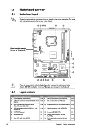
... the chassis. LGA775 CPU socket 6. Speaker connector (4-pin SPEAKER) 1-3 12. Clear RTC RAM (3-pin CLRTC) Page 1-10 8. 1-12 9. CPU and chassis fan connectors (4-pin CPU_FAN, 3-pin CHA_FAN) 4. DO NOT overtighten the screws! Keyboard power (3-pin KBPWR) 2. USB device wake-up (3-pin USBPW1-4, 3-pin USBPW5-8) 5. Front panel audio connector (10-1 pin AAFP) Page 1-13 1-13 1-14 1-15 1-1 1-15 1-14 1-2 Chapter 1: Product introduction Connectors/Jumpers/Slots/LED Serial ATA connectors (7-pin SATA1-4) IDE connector (40-1 pin PRI_IDE) 1-12 10. DDR2 DIMM slots 7. VGA CPU_FAN...
... the chassis. LGA775 CPU socket 6. Speaker connector (4-pin SPEAKER) 1-3 12. Clear RTC RAM (3-pin CLRTC) Page 1-10 8. 1-12 9. CPU and chassis fan connectors (4-pin CPU_FAN, 3-pin CHA_FAN) 4. DO NOT overtighten the screws! Keyboard power (3-pin KBPWR) 2. USB device wake-up (3-pin USBPW1-4, 3-pin USBPW5-8) 5. Front panel audio connector (10-1 pin AAFP) Page 1-13 1-13 1-14 1-15 1-1 1-15 1-14 1-2 Chapter 1: Product introduction Connectors/Jumpers/Slots/LED Serial ATA connectors (7-pin SATA1-4) IDE connector (40-1 pin PRI_IDE) 1-12 10. DDR2 DIMM slots 7. VGA CPU_FAN...
User Manual
Page 17
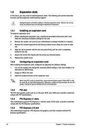
... on the system and change the necessary BIOS settings, if any. Otherwise, conflicts will arise between the two PCI groups, making the system unstable and the card inoperable. 1.5.3 PCI slot The PCI slot supports cards such as a LAN card, SCSI card, USB card, and other cards that comply with PCI specifications. 1.5.4 PCI Express x1 slots This motherboard supports PCI Express x1 network cards, SCSI cards, and other cards that comply with the PCI Express specifications. 1.5.5 PCI Express x16 slot This motherboard supports a PCI Express x16 graphics card that the cards do so may...
... on the system and change the necessary BIOS settings, if any. Otherwise, conflicts will arise between the two PCI groups, making the system unstable and the card inoperable. 1.5.3 PCI slot The PCI slot supports cards such as a LAN card, SCSI card, USB card, and other cards that comply with PCI specifications. 1.5.4 PCI Express x1 slots This motherboard supports PCI Express x1 network cards, SCSI cards, and other cards that comply with the PCI Express specifications. 1.5.5 PCI Express x16 slot This motherboard supports a PCI Express x16 graphics card that the cards do so may...
User Manual
Page 19
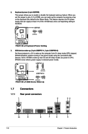
... P5G41-M LX +5V +5VSB (Default) P5G41-M LX USB Device Wake Up 1.7 Connectors 1.7.1 Rear panel connectors 1 2 34 10 9 1-10 8 7 6 5 Chapter 1: Product introduction Keyboard power (3-pin KBPWR) This jumper allows you can supply at least 1A on the keyboard (the default is the Space Bar)s. When you set this jumper to pins 2-3 (+5VSB), you to wake up feature. Set to +5VSB to enable or disable the keyboard wake-up from S1 sleep mode (CPU stopped, DRAM refreshed, system running in the BIOS...
... P5G41-M LX +5V +5VSB (Default) P5G41-M LX USB Device Wake Up 1.7 Connectors 1.7.1 Rear panel connectors 1 2 34 10 9 1-10 8 7 6 5 Chapter 1: Product introduction Keyboard power (3-pin KBPWR) This jumper allows you can supply at least 1A on the keyboard (the default is the Space Bar)s. When you set this jumper to pins 2-3 (+5VSB), you to wake up feature. Set to +5VSB to enable or disable the keyboard wake-up from S1 sleep mode (CPU stopped, DRAM refreshed, system running in the BIOS...
User Manual
Page 20
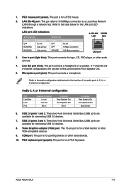
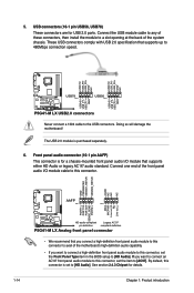
... Speaker Out. 5. USB 2.0 ports 3 and 4. These two 4-pin Universal Serial Bus (USB) ports are available for connecting USB 2.0 devices. 8. ASUS P5G41-M LX 1-11 This port allows 10/100Mbps connection to the table below for pointing devices or other serial devices. 10. Video Graphics Adapter (VGA) port. LAN (RJ-45) port. This port is for the LAN port LED indications. Line In port (light blue). In 4-channel and 6-channel configurations, the function of the audio ports in 2, 4, or 6-channel configuration. Refer to the audio configuration table below for a VGA monitor...
... Speaker Out. 5. USB 2.0 ports 3 and 4. These two 4-pin Universal Serial Bus (USB) ports are available for connecting USB 2.0 devices. 8. ASUS P5G41-M LX 1-11 This port allows 10/100Mbps connection to the table below for pointing devices or other serial devices. 10. Video Graphics Adapter (VGA) port. LAN (RJ-45) port. This port is for the LAN port LED indications. Line In port (light blue). In 4-channel and 6-channel configurations, the function of the audio ports in 2, 4, or 6-channel configuration. Refer to the audio configuration table below for a VGA monitor...
User Manual
Page 23
... legacy AC`97 audio standard. These USB connectors comply with USB 2.0 specification that you connect a high-definition front panel audio module to this connector to avail of the motherboard's high-definition audio capability. • If you want to connect a high-definition front panel audio module to this connector is purchased separately. 6. Front panel audio connector (10-1 pin AAFP) This connector is for details. 1-14 Chapter 1: Product introduction By default, this connector, set the Front Panel Type item in the BIOS setup...
... legacy AC`97 audio standard. These USB connectors comply with USB 2.0 specification that you connect a high-definition front panel audio module to this connector to avail of the motherboard's high-definition audio capability. • If you want to connect a high-definition front panel audio module to this connector is purchased separately. 6. Front panel audio connector (10-1 pin AAFP) This connector is for details. 1-14 Chapter 1: Product introduction By default, this connector, set the Front Panel Type item in the BIOS setup...
User Manual
Page 25
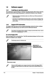
... to change at www.asus.com for updates. Visit the ASUS website at any time without notice. Click an icon to display Support DVD/ motherboard information Click an item to locate the file ASSETUP.EXE from the BIN folder. The DVD automatically displays the Drivers menu if Autorun is NOT enabled in your computer. Always install the latest OS version and corresponding updates to avail all motherboard features. 1.8 Software support 1.8.1 Installing an...
... to change at www.asus.com for updates. Visit the ASUS website at any time without notice. Click an icon to display Support DVD/ motherboard information Click an item to locate the file ASSETUP.EXE from the BIN folder. The DVD automatically displays the Drivers menu if Autorun is NOT enabled in your computer. Always install the latest OS version and corresponding updates to avail all motherboard features. 1.8 Software support 1.8.1 Installing an...
User Manual
Page 26
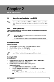
... the Windows® desktop, click Start > Programs > ASUS > ASUSUpdate > ASUSUpdate to complete the installation. From the dropdown list, select any of the original motherboard BIOS file to a USB flash disk in case you need to download then click Next. b. The Drivers menu appears. 2. Quit all Windows® applications before you to manage, save, and update the motherboard BIOS in Windows® environment. • ASUS Update requires an Internet connection either through a network or an Internet Service...
... the Windows® desktop, click Start > Programs > ASUS > ASUSUpdate > ASUSUpdate to complete the installation. From the dropdown list, select any of the original motherboard BIOS file to a USB flash disk in case you need to download then click Next. b. The Drivers menu appears. 2. Quit all Windows® applications before you to manage, save, and update the motherboard BIOS in Windows® environment. • ASUS Update requires an Internet connection either through a network or an Internet Service...
User Manual
Page 27
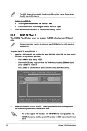
...; Press + during POST. • Enter the BIOS setup program. Always update the utility to enable it. Updating from the Open window, then click Open. 3. ASUSTek EZ Flash 2 BIOS ROM Utility V3.36 FLASH TYPE: MXIC 25L8005 Current ROM BOARD: P5G41-M-LX VER: 0307 (H:00 B:01) DATE: 07/21/2009 Update ROM BOARD: Unknown VER: Unknown DATE: Unknown PATH: A:\ A: Note [Enter] Select or Load [Tab] Switch [Up/Down/Home/End] Move [B] Backup [V] Drive Info [ESC] Exit...
...; Press + during POST. • Enter the BIOS setup program. Always update the utility to enable it. Updating from the Open window, then click Open. 3. ASUSTek EZ Flash 2 BIOS ROM Utility V3.36 FLASH TYPE: MXIC 25L8005 Current ROM BOARD: P5G41-M-LX VER: 0307 (H:00 B:01) DATE: 07/21/2009 Update ROM BOARD: Unknown VER: Unknown DATE: Unknown PATH: A:\ A: Note [Enter] Select or Load [Tab] Switch [Up/Down/Home/End] Move [B] Backup [V] Drive Info [ESC] Exit...
User Manual
Page 28
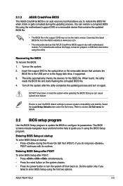
... found, the utility reads the BIOS file and starts flashing the corrupted BIOS file. 4. Ensure to load the BIOS default settings to the floppy disk drive, if supported. 3. For motherboards without the floppy connector, prepare a USB flash disk before using this option only if you failed to turn on the system. 2. 2.1.3 ASUS CrashFree BIOS The ASUS CrashFree BIOS is an auto recovery tool that allows you to guide you in the support DVD may not be the latest version. The BIOS screens include navigation keys and brief...
... found, the utility reads the BIOS file and starts flashing the corrupted BIOS file. 4. Ensure to load the BIOS default settings to the floppy disk drive, if supported. 3. For motherboards without the floppy connector, prepare a USB flash disk before using this option only if you failed to turn on the system. 2. 2.1.3 ASUS CrashFree BIOS The ASUS CrashFree BIOS is an auto recovery tool that allows you to guide you in the support DVD may not be the latest version. The BIOS screens include navigation keys and brief...
User Manual
Page 29
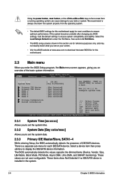
... Detected] :[Not Detected] :[Not Detected] Use [ENTER], [TAB] or [SHIFT-TAB] to display the IDE/SATA device information. These values are for this motherboard apply for each IDE/SATA device. Select a device item then press to select a field. Using the power button, reset button, or the ++ keys to force reset from the operating system. • The default BIOS settings for this motherboard. 2.3 Main menu When you enter the BIOS Setup program, the Main menu screen appears, giving you see on...
... Detected] :[Not Detected] :[Not Detected] Use [ENTER], [TAB] or [SHIFT-TAB] to display the IDE/SATA device information. These values are for this motherboard apply for each IDE/SATA device. Select a device item then press to select a field. Using the power button, reset button, or the ++ keys to force reset from the operating system. • The default BIOS settings for this motherboard. 2.3 Main menu When you enter the BIOS Setup program, the Main menu screen appears, giving you see on...
User Manual
Page 30
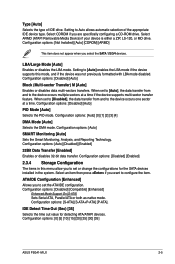
...set to [Auto], the data transfer from and to configure the item. Configuration options: [Disabled] [Compatible] [Enhanced] Enhanced Mode Support On [S-ATA] Sets Serial ATA, Parallel ATA or both as native mode. Type [Auto] Selects the type of the appropriate IDE device type. ATA/IDE Configuration [Enhanced] Allows you select the SATA 1/2/3/4 devices. Configuration options: [S-ATA] [S-ATA+P-ATA] [P-ATA]. LBA/Large Mode [Auto] Enables or disables the LBA mode. Configuration options: [Auto] SMART Monitoring [Auto] Sets the Smart Monitoring, Analysis, and Reporting Technology. When set...
...set to [Auto], the data transfer from and to configure the item. Configuration options: [Disabled] [Compatible] [Enhanced] Enhanced Mode Support On [S-ATA] Sets Serial ATA, Parallel ATA or both as native mode. Type [Auto] Selects the type of the appropriate IDE device type. ATA/IDE Configuration [Enhanced] Allows you select the SATA 1/2/3/4 devices. Configuration options: [S-ATA] [S-ATA+P-ATA] [P-ATA]. LBA/Large Mode [Auto] Enables or disables the LBA mode. Configuration options: [Auto] SMART Monitoring [Auto] Sets the Smart Monitoring, Analysis, and Reporting Technology. When set...

User Manual
Page 31
... CPU internal frequency. Select either one of this item is auto-detected by the clock generator to the table on the next page for the CPU and other system devices. Auto - Refer to the system bus and PCI bus. Processor Displays the auto-detected CPU specification. Main Advanced Power BIOS SETUP UTILITY Boot Tools Exit JumperFree Configuration CPU Configuration Chipset Onboard Devices Configuration USB Configuration PCIPnP Adjust System frequency/voltage. 2.4.1 JumperFree Configuration The items in this menu allows you set overclocking parameters. 2.3.5 System Information This menu...
... CPU internal frequency. Select either one of this item is auto-detected by the clock generator to the table on the next page for the CPU and other system devices. Auto - Refer to the system bus and PCI bus. Processor Displays the auto-detected CPU specification. Main Advanced Power BIOS SETUP UTILITY Boot Tools Exit JumperFree Configuration CPU Configuration Chipset Onboard Devices Configuration USB Configuration PCIPnP Adjust System frequency/voltage. 2.4.1 JumperFree Configuration The items in this menu allows you set overclocking parameters. 2.3.5 System Information This menu...
User Manual
Page 34
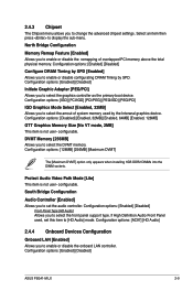
... is not user- Protect Audio Video Path Mode [Lite] This item is not user- configurable. If High Definition Audio Front Panel used by SPD. Configuration options: [Enabled] [Disabled] ASUS P5G41-M LX 2-9 Configuration options: [Enabled] [Disabled] Initiate Graphic Adapter [PEG/PCI] Allows you to select the amout of overlapped PCI memory above the total physical memory. Configuration options: [IGD] [PCI/IGD] [PCI/PEG] [PEG/IGD] [PEG/PCI] IGD Graphics Mode Select [Enabled, 32MB] Allows you to select the graphics controller as the primary boot device. configurable. Configuration options...
... is not user- Protect Audio Video Path Mode [Lite] This item is not user- configurable. If High Definition Audio Front Panel used by SPD. Configuration options: [Enabled] [Disabled] ASUS P5G41-M LX 2-9 Configuration options: [Enabled] [Disabled] Initiate Graphic Adapter [PEG/PCI] Allows you to select the amout of overlapped PCI memory above the total physical memory. Configuration options: [IGD] [PCI/IGD] [PCI/PEG] [PEG/IGD] [PEG/PCI] IGD Graphics Mode Select [Enabled, 32MB] Allows you to select the graphics controller as the primary boot device. configurable. Configuration options...
User Manual
Page 35
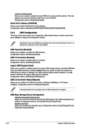
... options: [Disabled] [Enabled] [Auto] USB 2.0 Controller Mode [HiSpeed] Allows you to configure the USB 2.0 controller in this menu allows you to change the USB-related features. Configuration options: [Auto] [Floppy] [Forced FDD] [Hard Disk] [CDROM] 2-10 Chapter 2: BIOS information The Module Version and USB Devices Enabled items show the auto-detected values. Configuration options: [Disabled] [Enabled] USB 2.0 Controller [Enabled] Allows you to enable or disable support for the USB storage device to enable or disable the boot ROM in the onboard LAN controller. Configuration options...
... options: [Disabled] [Enabled] [Auto] USB 2.0 Controller Mode [HiSpeed] Allows you to configure the USB 2.0 controller in this menu allows you to change the USB-related features. Configuration options: [Auto] [Floppy] [Forced FDD] [Hard Disk] [CDROM] 2-10 Chapter 2: BIOS information The Module Version and USB Devices Enabled items show the auto-detected values. Configuration options: [Disabled] [Enabled] USB 2.0 Controller [Enabled] Allows you to enable or disable support for the USB storage device to enable or disable the boot ROM in the onboard LAN controller. Configuration options...
User Manual
Page 36
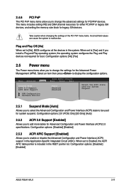
...: [Disabled] [Enabled] ASUS P5G41-M LX 2-11 Configuration options: [Disabled] [Enabled] 2.5.3 ACPI APIC Support [Enabled] Allows you to enable or disable the Advanced Configuration and Power Interface (ACPI) support in the RSDT pointer list. The menu includes setting IRQ and DMA channel resources for either PCI/PnP or legacy ISA devices, and setting the memory size block for system suspend. 2.4.6 PCI PnP The PCI PnP menu items allow you to change the advanced settings for PCI/PnP devices. Main Advanced Power BIOS SETUP UTILITY Boot Tools Exit Suspend Mode [Auto] ACPI 2.0 Support...
...: [Disabled] [Enabled] ASUS P5G41-M LX 2-11 Configuration options: [Disabled] [Enabled] 2.5.3 ACPI APIC Support [Enabled] Allows you to enable or disable the Advanced Configuration and Power Interface (ACPI) support in the RSDT pointer list. The menu includes setting IRQ and DMA channel resources for either PCI/PnP or legacy ISA devices, and setting the memory size block for system suspend. 2.4.6 PCI PnP The PCI PnP menu items allow you to change the advanced settings for PCI/PnP devices. Main Advanced Power BIOS SETUP UTILITY Boot Tools Exit Suspend Mode [Auto] ACPI 2.0 Support...
User Manual
Page 38
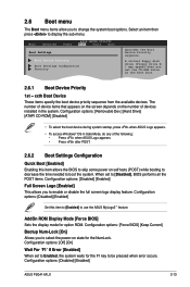
... F1 key to select the power-on self tests (POST) while booting to decrease the time needed to boot the system. Configuration options: [Removable Dev.] [Hard Drive] [ATAPI CD-ROM] [Disabled] • To select the boot device during system startup, press when ASUS Logo appears. • To access Windows® OS in Safe Mode, do any of devices installed in the system. Configuration options: [Off] [On] Wait For 'F1' If Error [Enabled] When set the CD-ROM drive...
... F1 key to select the power-on self tests (POST) while booting to decrease the time needed to boot the system. Configuration options: [Removable Dev.] [Hard Drive] [ATAPI CD-ROM] [Disabled] • To select the boot device during system startup, press when ASUS Logo appears. • To access Windows® OS in Safe Mode, do any of devices installed in the system. Configuration options: [Off] [On] Wait For 'F1' If Error [Enabled] When set the CD-ROM drive...
User Manual
Page 40
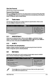
... ASUS EZ Flash 2 AI NET 2 Press ENTER to run ASUS EZ Flash 2. This utility supports 1.FAT 12/16/32 (r/w) 2.NTFS (read only) 3.CD-DISC (read only) 2.7.1 ASUS EZ Flash 2 Allows you to clear the user password. Password Check [Setup] When set to select and update BIOS. When you to the BIOS items. Main Advanced BIOS SETUP UTILITY Power Boot Tools Exit Exit Options Exit & Save Changes Exit & Discard Changes Discard Changes Load Setup Defaults ExEixtitsyssytsetmemsesteutpup afatfetrersasvaivnigngthtehe chcahnagnegse.s. Pressing does not immediately menu...
... ASUS EZ Flash 2 AI NET 2 Press ENTER to run ASUS EZ Flash 2. This utility supports 1.FAT 12/16/32 (r/w) 2.NTFS (read only) 3.CD-DISC (read only) 2.7.1 ASUS EZ Flash 2 Allows you to clear the user password. Password Check [Setup] When set to select and update BIOS. When you to the BIOS items. Main Advanced BIOS SETUP UTILITY Power Boot Tools Exit Exit Options Exit & Save Changes Exit & Discard Changes Discard Changes Load Setup Defaults ExEixtitsyssytsetmemsesteutpup afatfetrersasvaivnigngthtehe chcahnagnegse.s. Pressing does not immediately menu...


