User Manual
Page 2
... Computer Inc. ("ASUS"). SPECIFICATIONS AND INFORMATION CONTAINED IN THIS MANUAL ARE FURNISHED FOR INFORMATIONAL USE ONLY, AND ARE SUBJECT TO CHANGE AT ANY TIME WITHOUT NOTICE, AND SHOULD NOT BE CONSTRUED AS A COMMITMENT BY ASUS. ii Copies of their respective companies, and are included in this manual may or may contain copyrighted software that is repaired, modified or altered...
... Computer Inc. ("ASUS"). SPECIFICATIONS AND INFORMATION CONTAINED IN THIS MANUAL ARE FURNISHED FOR INFORMATIONAL USE ONLY, AND ARE SUBJECT TO CHANGE AT ANY TIME WITHOUT NOTICE, AND SHOULD NOT BE CONSTRUED AS A COMMITMENT BY ASUS. ii Copies of their respective companies, and are included in this manual may or may contain copyrighted software that is repaired, modified or altered...
User Manual
Page 3
... 1-4 1.4.2 Memory configurations 1-4 1.5 Expansion slots 1-6 1.5.1 Installing an expansion card 1-6 1.5.2 Configuring an expansion card 1-6 1.5.3 PCI slots 1-6 1.5.4 PCI Express x16 slot 1-6 1.6 Jumpers 1-7 1.7 Connectors 1-9 1.7.1 Rear panel ports 1-9 1.7.2 Internal connectors 1-10 1.8 Software support 1-16 1.8.1 Installing an operating system 1-16 1.8.2 Support DVD information 1-16 Chapter 2: BIOS information 2.1 Managing and updating your BIOS 2-1 2.1.1 ASUS Update utility 2-1 2.1.2 ASUS EZ Flash 2 2-2 2.1.3 ASUS CrashFree BIOS 2-3 2.2 BIOS setup program 2-3 2.3 Main menu...
... 1-4 1.4.2 Memory configurations 1-4 1.5 Expansion slots 1-6 1.5.1 Installing an expansion card 1-6 1.5.2 Configuring an expansion card 1-6 1.5.3 PCI slots 1-6 1.5.4 PCI Express x16 slot 1-6 1.6 Jumpers 1-7 1.7 Connectors 1-9 1.7.1 Rear panel ports 1-9 1.7.2 Internal connectors 1-10 1.8 Software support 1-16 1.8.1 Installing an operating system 1-16 1.8.2 Support DVD information 1-16 Chapter 2: BIOS information 2.1 Managing and updating your BIOS 2-1 2.1.1 ASUS Update utility 2-1 2.1.2 ASUS EZ Flash 2 2-2 2.1.3 ASUS CrashFree BIOS 2-3 2.2 BIOS setup program 2-3 2.3 Main menu...
User Manual
Page 8
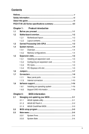
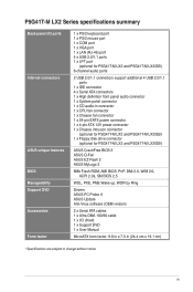
... PCIe x16 slot 1 x PCIe x1 slot (optional) 2 x PCI slots 1 x Ultra DMA 100/66 connector 4 x Serial ATA 3Gb/s ports P5G41T-M LX2/GB and P5G41T-M LX2/GB/LPT: Realtek® RTL8112L Gigabit Ethernet PCIe controller P5G41T-M LX2: Realtek® RTL8103EL 10/100Mbps Ethernet PCIe controller VIA® VT1705 High Definition Audio 6-channel CODEC Supports Multi-streaming technology Supports up to 8GB system memory * Refer to www.asus.com for the Intel® CPU support list. P5G41T-M LX2 Series specifications summary CPU Chipset Front Side Bus Memory Graphics Expansion slots Storage LAN Audio USB...
... PCIe x16 slot 1 x PCIe x1 slot (optional) 2 x PCI slots 1 x Ultra DMA 100/66 connector 4 x Serial ATA 3Gb/s ports P5G41T-M LX2/GB and P5G41T-M LX2/GB/LPT: Realtek® RTL8112L Gigabit Ethernet PCIe controller P5G41T-M LX2: Realtek® RTL8103EL 10/100Mbps Ethernet PCIe controller VIA® VT1705 High Definition Audio 6-channel CODEC Supports Multi-streaming technology Supports up to 8GB system memory * Refer to www.asus.com for the Intel® CPU support list. P5G41T-M LX2 Series specifications summary CPU Chipset Front Side Bus Memory Graphics Expansion slots Storage LAN Audio USB...
User Manual
Page 9
...ports Internal connectors ASUS unique features BIOS Manageability Support DVD Accessories Form factor 1 x PS/2 keyboard port 1 x PS/2 mouse port 1 x COM port 1 x VGA port 1 x LAN (RJ-45) port 4 x USB 2.0/1.1 ports 1 x LPT port (optional for P5G41T-M LX2 and P5G41T-M LX2/GB) 6-channel audio ports 2 USB 2.0/1.1 connectors support additional 4 USB 2.0/1.1 ports 1 x IDE connector 4 x Serial ATA connectors 1 x High definition front panel audio connector 1 x System panel connector 1 x CD audio-in connector 1 x CPU fan connector 1 x Chassis fan connector 1 x 24-pin EATX power connector 1 x 4-pin ATX...
...ports Internal connectors ASUS unique features BIOS Manageability Support DVD Accessories Form factor 1 x PS/2 keyboard port 1 x PS/2 mouse port 1 x COM port 1 x VGA port 1 x LAN (RJ-45) port 4 x USB 2.0/1.1 ports 1 x LPT port (optional for P5G41T-M LX2 and P5G41T-M LX2/GB) 6-channel audio ports 2 USB 2.0/1.1 connectors support additional 4 USB 2.0/1.1 ports 1 x IDE connector 4 x Serial ATA connectors 1 x High definition front panel audio connector 1 x System panel connector 1 x CD audio-in connector 1 x CPU fan connector 1 x Chassis fan connector 1 x 24-pin EATX power connector 1 x 4-pin ATX...
User Manual
Page 15
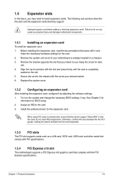
... and the card inoperable. 1.5.3 PCI slots The PCI slot supports cards such as a LAN card, SCSI card, USB card, and other cards that comply with PCI specifications. 1.5.4 PCI Express x16 slot This motherboard supports a PCI Express x16 graphics card that came with the PCI Express specifications. Secure the card to the card. 3. 1.5 Expansion slots In the future, you may cause you physical injury and damage motherboard components. 1.5.1 Installing an expansion card To install an expansion card: 1. Turn on BIOS setup. 2. Install the software drivers for later use . Remove the...
... and the card inoperable. 1.5.3 PCI slots The PCI slot supports cards such as a LAN card, SCSI card, USB card, and other cards that comply with PCI specifications. 1.5.4 PCI Express x16 slot This motherboard supports a PCI Express x16 graphics card that came with the PCI Express specifications. Secure the card to the card. 3. 1.5 Expansion slots In the future, you may cause you physical injury and damage motherboard components. 1.5.1 Installing an expansion card To install an expansion card: 1. Turn on BIOS setup. 2. Install the software drivers for later use . Remove the...
User Manual
Page 17
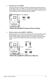
... (Default) P5G41T-M LX2/GB/LPT USB Device Wake Up Chapter 1: Product introduction 1-8 Set these jumpers to +5V to wake up the computer from S3 and S4 sleep modes (no power to enable or disable the keyboard wake-up feature. 2. Keyboard power (3-pin KBPWR) This jumper allows you can supply at least 1A on the keyboard. This feature requires an ATX power supply that can wake up the computer from S1 sleep mode (CPU stopped, DRAM refreshed, system running in low power mode) using the connected USB devices. USB device wake...
... (Default) P5G41T-M LX2/GB/LPT USB Device Wake Up Chapter 1: Product introduction 1-8 Set these jumpers to +5V to wake up the computer from S3 and S4 sleep modes (no power to enable or disable the keyboard wake-up feature. 2. Keyboard power (3-pin KBPWR) This jumper allows you can supply at least 1A on the keyboard. This feature requires an ATX power supply that can wake up the computer from S1 sleep mode (CPU stopped, DRAM refreshed, system running in low power mode) using the connected USB devices. USB device wake...
User Manual
Page 18
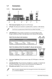
... Out port (lime). This port connects a microphone. LPT port. The LPT port is for P5G41T-M LX2 and P5G41T-M LX2/GB. 3. This port allows connection to the table below for the function of this port becomes Front Speaker Out. 6. In 4-channel and 6-channel configurations, the function of the audio ports in 2, 4, or 6-channel configuration. 1-9 ASUS P5G41T-M LX2 Series This 25-pin port connects to the audio configuration table on the next page for the LAN port LED indications. LAN (RJ-45) port. This port is an optional...
... Out port (lime). This port connects a microphone. LPT port. The LPT port is for P5G41T-M LX2 and P5G41T-M LX2/GB. 3. This port allows connection to the table below for the function of this port becomes Front Speaker Out. 6. In 4-channel and 6-channel configurations, the function of the audio ports in 2, 4, or 6-channel configuration. 1-9 ASUS P5G41T-M LX2 Series This 25-pin port connects to the audio configuration table on the next page for the LAN port LED indications. LAN (RJ-45) port. This port is an optional...

User Manual
Page 19
... not boot. • We recommend that you use a PSU with a higher power output when configuring a system with ATX 12V Specification 2.0 or later version and provides a minimum power of 400W. • DO NOT forget to install additional devices. These two 4-pin Universal Serial Bus (USB) ports are designed to the Recommended Power Supply Wattage Calculator at http://support.asus. This port is for connecting USB 2.0 devices. 9. The power supply plugs are available for a VGA monitor or other serial devices. 11. USB 2.0 ports 1 and...
... not boot. • We recommend that you use a PSU with a higher power output when configuring a system with ATX 12V Specification 2.0 or later version and provides a minimum power of 400W. • DO NOT forget to install additional devices. These two 4-pin Universal Serial Bus (USB) ports are designed to the Recommended Power Supply Wattage Calculator at http://support.asus. This port is for connecting USB 2.0 devices. 9. The power supply plugs are available for a VGA monitor or other serial devices. 11. USB 2.0 ports 1 and...
User Manual
Page 20
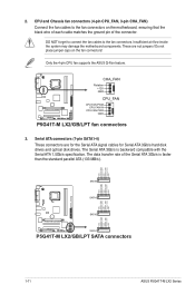
... RSATA_TXN2 RSATA_TXP2 GND GND RSATA_RXN1 RSATA_RXP1 GND RSATA_TXN1 RSATA_TXP1 GND P5G41T-M LX2/GB/LPT SATA2 SATA1 P5G41T-M LX2/GB/LPT SATA connectors 1-11 ASUS P5G41T-M LX2 Series 2. Only the 4-pin CPU fan supports the ASUS Q-Fan feature. Serial ATA connectors (7-pin SATA1-4) These connectors are not jumpers! P5G41T-M LX2/GB/LPT CHA_FAN Rotation +12V GND CPU_FAN CPU FAN PWM CPU FAN IN CPU FAN PWR GND P5G41T-M LX2/GB/LPT fan connectors 3. CPU and Chassis fan connectors (4-pin CPU_FAN, 3-pin CHA_FAN) Connect the fan cables to the fan connectors. The data transfer rate of the...
... RSATA_TXN2 RSATA_TXP2 GND GND RSATA_RXN1 RSATA_RXP1 GND RSATA_TXN1 RSATA_TXP1 GND P5G41T-M LX2/GB/LPT SATA2 SATA1 P5G41T-M LX2/GB/LPT SATA connectors 1-11 ASUS P5G41T-M LX2 Series 2. Only the 4-pin CPU fan supports the ASUS Q-Fan feature. Serial ATA connectors (7-pin SATA1-4) These connectors are not jumpers! P5G41T-M LX2/GB/LPT CHA_FAN Rotation +12V GND CPU_FAN CPU FAN PWM CPU FAN IN CPU FAN PWR GND P5G41T-M LX2/GB/LPT fan connectors 3. CPU and Chassis fan connectors (4-pin CPU_FAN, 3-pin CHA_FAN) Connect the fan cables to the fan connectors. The data transfer rate of the...

User Manual
Page 25
...; Motherboard settings and hardware options vary. Always install the latest OS version and corresponding updates to maximize the features of the Support DVD are subject to the optical drive. Double-click the ASSETUP.EXE to run the Support DVD Place the Support DVD to change at www.asus.com for updates. The following screen is enabled in your OS documentation for detailed information. • Ensure that you install Windows®...
...; Motherboard settings and hardware options vary. Always install the latest OS version and corresponding updates to maximize the features of the Support DVD are subject to the optical drive. Double-click the ASSETUP.EXE to run the Support DVD Place the Support DVD to change at www.asus.com for updates. The following screen is enabled in your OS documentation for detailed information. • Ensure that you install Windows®...
User Manual
Page 26
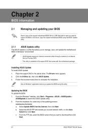
... original motherboard BIOS file to restore the BIOS in the future. Select Update BIOS from the Internet a. Quit all Windows® applications before you need to a USB flash disk in case you update the BIOS using the ASUS Update utility. 2.1.1 ASUS Update utility The ASUS Update is a utility that allows you to download then click Next. 2-1 ASUS P5G41T-M LX2 Series From the Windows® desktop, click Start > Programs > ASUS > ASUSUpdate > ASUSUpdate to complete the installation. The Drivers menu appears. 2. Chapter 2 BIOS information 2.1 Managing and updating your BIOS...
... original motherboard BIOS file to restore the BIOS in the future. Select Update BIOS from the Internet a. Quit all Windows® applications before you need to a USB flash disk in case you update the BIOS using the ASUS Update utility. 2.1.1 ASUS Update utility The ASUS Update is a utility that allows you to download then click Next. 2-1 ASUS P5G41T-M LX2 Series From the Windows® desktop, click Start > Programs > ASUS > ASUSUpdate > ASUSUpdate to complete the installation. The Drivers menu appears. 2. Chapter 2 BIOS information 2.1 Managing and updating your BIOS...
User Manual
Page 27
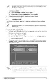
....44 FLASH TYPE: MXIC 25L8005 Current ROM BOARD:P5G41T-M LX2/GB/LPT VER:0305 (H:00 B:00) DATE: 10/29/2009 Update ROM BOARD: Unknown VER: Unknown DATE: Unknown PATH: A:\ A: Note [Enter] Select or Load [Tab] Switch [Up/Down/Home/End] Move [B] Backup [V] Drive Info [ESC] Exit • This function supports USB flash disks with FAT 32/16 format and single partition only. • DO NOT shut down or reset...
....44 FLASH TYPE: MXIC 25L8005 Current ROM BOARD:P5G41T-M LX2/GB/LPT VER:0305 (H:00 B:00) DATE: 10/29/2009 Update ROM BOARD: Unknown VER: Unknown DATE: Unknown PATH: A:\ A: Note [Enter] Select or Load [Tab] Switch [Up/Down/Home/End] Move [B] Backup [V] Drive Info [ESC] Exit • This function supports USB flash disks with FAT 32/16 format and single partition only. • DO NOT shut down or reset...
User Manual
Page 28
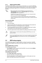
... floppy connector, prepare a USB flash disk before using the first two options. 2-3 ASUS P5G41T-M LX2 Series Insert the support DVD to the optical drive or the removable device that contains the BIOS file to the USB port or to guide you do not press , POST continues with motherboard models. Recovering the BIOS To recover the BIOS: 1. You can cause system boot failure! Turn on again. The utility automatically checks the devices for details. 2.2 BIOS setup program Use the BIOS Setup program to enter BIOS Setup using this utility, rename the BIOS file...
... floppy connector, prepare a USB flash disk before using the first two options. 2-3 ASUS P5G41T-M LX2 Series Insert the support DVD to the optical drive or the removable device that contains the BIOS file to the USB port or to guide you do not press , POST continues with motherboard models. Recovering the BIOS To recover the BIOS: 1. You can cause system boot failure! Turn on again. The utility automatically checks the devices for details. 2.2 BIOS setup program Use the BIOS Setup program to enter BIOS Setup using this utility, rename the BIOS file...
User Manual
Page 29
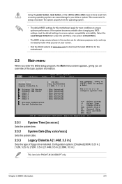
.... 2.3.3 Legacy Diskette A [1.44M, 3.5 in .] Use [ENTER], [TAB] or [SHIFT-TAB] to select a field. Using the power button, reset button, or the ++ keys to force reset from the operating system. • The default BIOS settings for this motherboard apply for most conditions to ensure optimum performance. Configuration options: [Disabled] [360K, 5.25 in.] [1.2M, 5.25 in.] [720K, 3.5 in.] [1.44M, 3.5 in.] [2.88M, 3.5 in this motherboard. 2.3 Main menu When you enter the BIOS Setup program, the Main menu screen appears...
.... 2.3.3 Legacy Diskette A [1.44M, 3.5 in .] Use [ENTER], [TAB] or [SHIFT-TAB] to select a field. Using the power button, reset button, or the ++ keys to force reset from the operating system. • The default BIOS settings for this motherboard apply for most conditions to ensure optimum performance. Configuration options: [Disabled] [360K, 5.25 in.] [1.2M, 5.25 in.] [720K, 3.5 in.] [1.44M, 3.5 in.] [2.88M, 3.5 in this motherboard. 2.3 Main menu When you enter the BIOS Setup program, the Main menu screen appears...
User Manual
Page 30
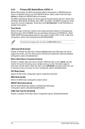
... LBA mode disabled. These values are specifically configuring a CD-ROM drive. Configuration options: [Not Installed] [Auto] [CDROM] [ARMD] This item does not appear when you are not user-configurable. When this item is installed in the system. Configuration options: [Disabled] [Enabled] 2-5 ASUS P5G41T-M LX2 Series Select CDROM if you select the SATA 1/2/3/4 devices. Select ARMD (ATAPI Removable Media Device) if your device is a separate submenu for each IDE/SATA device. Setting to display the IDE/SATA device information. When this item is set to [Disabled...
... LBA mode disabled. These values are specifically configuring a CD-ROM drive. Configuration options: [Not Installed] [Auto] [CDROM] [ARMD] This item does not appear when you are not user-configurable. When this item is installed in the system. Configuration options: [Disabled] [Enabled] 2-5 ASUS P5G41T-M LX2 Series Select CDROM if you select the SATA 1/2/3/4 devices. Select ARMD (ATAPI Removable Media Device) if your device is a separate submenu for each IDE/SATA device. Setting to display the IDE/SATA device information. When this item is set to [Disabled...
User Manual
Page 31
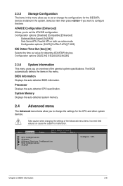
... BIOS information. Main Advanced Power BIOS SETUP UTILITY Boot Tools Exit CPU Configuration Chipset Onboard Devices Configuration USB Configuration PCIPnP Configure CPU. Take caution when changing the settings of the general system specifications. ATA/IDE Configuration [Enhanced] Allows you an overview of the Advanced menu items. Incorrect field values can cause the system to set or change the settings for the CPU and other system devices. Chapter 2: BIOS information 2-6 Configuration options: [Disabled] [Compatible] [Enhanced] Enhanced Mode Support On [S-ATA] Sets Serial...
... BIOS information. Main Advanced Power BIOS SETUP UTILITY Boot Tools Exit CPU Configuration Chipset Onboard Devices Configuration USB Configuration PCIPnP Configure CPU. Take caution when changing the settings of the general system specifications. ATA/IDE Configuration [Enhanced] Allows you an overview of the Advanced menu items. Incorrect field values can cause the system to set or change the settings for the CPU and other system devices. Chapter 2: BIOS information 2-6 Configuration options: [Disabled] [Compatible] [Enhanced] Enhanced Mode Support On [S-ATA] Sets Serial...
User Manual
Page 33
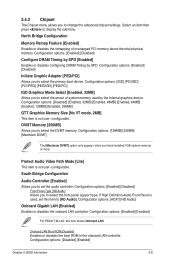
... memory. configurable. If High Definition Audio Front Panel is not user- South Bridge Configuration Audio Controller [Enabled] Allows you to set this item shows Onboard LAN. Configuration options: [AC97] [HD Audio] Onboard Gigabit LAN [Enabled] Enables or disables the onboard LAN controller. Protect Audio Video Path Mode [Lite] This item is used by SPD. Onboard LAN Boot ROM [Disabled] Enables or disables the boot ROM in the onboard LAN controller. Configuration options: [Enabled] [Disabled] Initiate Graphic Adapter [PEG/PCI] Allows you to select the front panel support type...
... memory. configurable. If High Definition Audio Front Panel is not user- South Bridge Configuration Audio Controller [Enabled] Allows you to set this item shows Onboard LAN. Configuration options: [AC97] [HD Audio] Onboard Gigabit LAN [Enabled] Enables or disables the onboard LAN controller. Protect Audio Video Path Mode [Lite] This item is used by SPD. Onboard LAN Boot ROM [Disabled] Enables or disables the boot ROM in the onboard LAN controller. Configuration options: [Enabled] [Disabled] Initiate Graphic Adapter [PEG/PCI] Allows you to select the front panel support type...
User Manual
Page 35
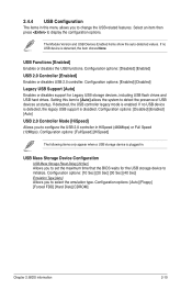
...the USB controller legacy mode is plugged in. Configuration options: [10 Sec] [20 Sec] [30 Sec] [40 Sec] Emulation Type [Auto] Allows you to change the USB-related features. Configuration options: [Auto] [Floppy] [Forced FDD] [Hard Disk] [CDROM] Chapter 2: BIOS information 2-10 Select an item then press to set the maximum time that the BIOS waits for Legacy USB storage devices, including USB flash drives and USB hard drives. USB Functions [Enabled] Enables or disables the USB functions. Configuration options: [Enabled] [Disabled] Legacy USB Support [Auto] Enables or disables support...
...the USB controller legacy mode is plugged in. Configuration options: [10 Sec] [20 Sec] [30 Sec] [40 Sec] Emulation Type [Auto] Allows you to change the USB-related features. Configuration options: [Auto] [Floppy] [Forced FDD] [Hard Disk] [CDROM] Chapter 2: BIOS information 2-10 Select an item then press to set the maximum time that the BIOS waits for Legacy USB storage devices, including USB flash drives and USB hard drives. USB Functions [Enabled] Enables or disables the USB functions. Configuration options: [Enabled] [Disabled] Legacy USB Support [Auto] Enables or disables support...
User Manual
Page 36
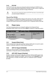
...-M LX2 Series Plug and Play O/S [No] When this item is included in the RSDT pointer list. Main Advanced Power BIOS SETUP UTILITY Boot Tools Exit Suspend Mode [Auto] ACPI 2.0 Support [Enabled] ACPI APIC Support [Enabled] APM Configuration Hardware Monitor Select the ACPI state used for System Suspend. 2.5.1 Suspend Mode [Auto] Selects the Advanced Configuration and Power Interface (ACPI) state to be used for boot. Configuration options: [S1 (POS) Only] [S3 Only] [Auto] 2.5.2 ACPI 2.0 Support [Enabled] Allows you to add more tables for legacy ISA devices. 2.4.5 PCI PnP...
...-M LX2 Series Plug and Play O/S [No] When this item is included in the RSDT pointer list. Main Advanced Power BIOS SETUP UTILITY Boot Tools Exit Suspend Mode [Auto] ACPI 2.0 Support [Enabled] ACPI APIC Support [Enabled] APM Configuration Hardware Monitor Select the ACPI state used for System Suspend. 2.5.1 Suspend Mode [Auto] Selects the Advanced Configuration and Power Interface (ACPI) state to be used for boot. Configuration options: [S1 (POS) Only] [S3 Only] [Auto] 2.5.2 ACPI 2.0 Support [Enabled] Allows you to add more tables for legacy ISA devices. 2.4.5 PCI PnP...
User Manual
Page 38
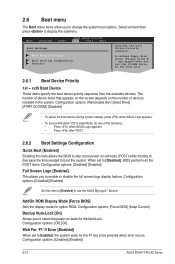
... screen logo display feature. The number of device items that appears on the screen depends on state for option ROM. When set to [Disabled], BIOS performs all the POST items. Configuration options: [Disabled] [Enabled] Full Screen Logo [Enabled] This allows you to boot the system. 2.6 Boot menu The Boot menu items allow you set the CD-ROM drive as the first boot device. 2.6.1 Boot Device Priority 1st ~ xxth Boot Device These items specify the boot device priority sequence from the available devices. Main Advanced Power BIOS SETUP UTILITY Boot...
... screen logo display feature. The number of device items that appears on the screen depends on state for option ROM. When set to [Disabled], BIOS performs all the POST items. Configuration options: [Disabled] [Enabled] Full Screen Logo [Enabled] This allows you to boot the system. 2.6 Boot menu The Boot menu items allow you set the CD-ROM drive as the first boot device. 2.6.1 Boot Device Priority 1st ~ xxth Boot Device These items specify the boot device priority sequence from the available devices. Main Advanced Power BIOS SETUP UTILITY Boot...


