User Manual
Page 3
Contents Notices...v Safety information vi About this guide vii P5G41-M LX specifications summary viii Chapter 1: Product introduction 1.1 Before you proceed 1-1 1.2 Motherboard overview 1-2 1.2.1 Motherboard layout 1-2 1.2.2 Layout contents 1-2 1.3 Central Processing Unit (CPU 1-3 1.4 System memory 1-3 1.4.1 Overview...16 1.8.1 Installing an operating system 1-16 1.8.2 Support DVD information 1-16 Chapter 2: BIOS information 2.1 Managing and updating your BIOS 2-1 2.1.1 ASUS Update utility 2-1 2.1.2 ASUS EZ Flash 2 2-2 2.1.3 ASUS CrashFree BIOS 2-3 2.2 BIOS setup program 2-3 iii
Contents Notices...v Safety information vi About this guide vii P5G41-M LX specifications summary viii Chapter 1: Product introduction 1.1 Before you proceed 1-1 1.2 Motherboard overview 1-2 1.2.1 Motherboard layout 1-2 1.2.2 Layout contents 1-2 1.3 Central Processing Unit (CPU 1-3 1.4 System memory 1-3 1.4.1 Overview...16 1.8.1 Installing an operating system 1-16 1.8.2 Support DVD information 1-16 Chapter 2: BIOS information 2.1 Managing and updating your BIOS 2-1 2.1.1 ASUS Update utility 2-1 2.1.2 ASUS EZ Flash 2 2-2 2.1.3 ASUS CrashFree BIOS 2-3 2.2 BIOS setup program 2-3 iii
User Manual
Page 8
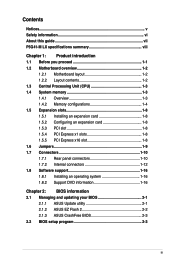
... Supports Jack-detection and Multi-streaming technologies Supports up to www.asus.com for Intel® CPU support list. P5G41-M LX specifications summary CPU Chipset Front Side Bus Memory Graphics Expansion slots Storage LAN Audio USB ASUS special features LGA775 socket for Intel® Core™2 Quad ...-core CPU * Refer to 8 x USB 2.0/1.1 ports (4 ports at mid-board, 4 ports at back panel) ASUS CrashFree BIOS 3 ASUS Q-Fan ASUS EZ Flash 2 ASUS MyLogo 2 ASUS AI NET 2 ASUS Turbo Key (continued on the next page) viii We recommend a maximum of 3GB system memory if you install a...
... Supports Jack-detection and Multi-streaming technologies Supports up to www.asus.com for Intel® CPU support list. P5G41-M LX specifications summary CPU Chipset Front Side Bus Memory Graphics Expansion slots Storage LAN Audio USB ASUS special features LGA775 socket for Intel® Core™2 Quad ...-core CPU * Refer to 8 x USB 2.0/1.1 ports (4 ports at mid-board, 4 ports at back panel) ASUS CrashFree BIOS 3 ASUS Q-Fan ASUS EZ Flash 2 ASUS MyLogo 2 ASUS AI NET 2 ASUS Turbo Key (continued on the next page) viii We recommend a maximum of 3GB system memory if you install a...
User Manual
Page 9
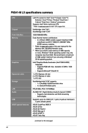
P5G41-M LX specifications summary Back panel I/O ports Internal I/O connectors BIOS features Support DVD contents Accessories Form factor 1 x PS/2 keyboard port 1 x PS/2 mouse port 1 x COM port 1 x VGA port 1 x LAN (...-pin EATX power connector 1 x 4-pin ATX 12V power connector 8Mb Flash ROM, AMI BIOS, PnP, DMI 2.0, WfM 2.0, ACPI v2.0a, SM BIOS v2.5 Drivers ASUS PC Probe II ASUS LiveUpdate Utility Anti-virus software (OEM version) 2 x Serial ATA cables 1 x UltraDMA 100/66 cable 1 x I/O shield User Manual MicroATX form factor: 9.6 in x 7.2 in (24...
P5G41-M LX specifications summary Back panel I/O ports Internal I/O connectors BIOS features Support DVD contents Accessories Form factor 1 x PS/2 keyboard port 1 x PS/2 mouse port 1 x COM port 1 x VGA port 1 x LAN (...-pin EATX power connector 1 x 4-pin ATX 12V power connector 8Mb Flash ROM, AMI BIOS, PnP, DMI 2.0, WfM 2.0, ACPI v2.0a, SM BIOS v2.5 Drivers ASUS PC Probe II ASUS LiveUpdate Utility Anti-virus software (OEM version) 2 x Serial ATA cables 1 x UltraDMA 100/66 cable 1 x I/O shield User Manual MicroATX form factor: 9.6 in x 7.2 in (24...
User Manual
Page 21
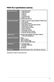
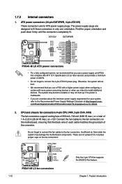
...to the Recommended Power Supply Wattage Calculator at +12V. ATX12V EATXPWR +12V DC +12V DC P5G41-M LX GND GND +3 Volts +12 Volts +12 Volts +5V Standby Power OK PIN 1 GND +5 Volts GND +5 Volts GND +3...88 W max.) or a total of 1 A~2.22 A (26.64 W max.) at http://support.asus. These are for ATX power supply plugs. P5G41-M LX CPU_FAN GND CPU FAN PWR CPU FAN IN CPU FAN PWM CHA_FAN GND +12V Rotation Only the 4-pin... use a PSU with a higher power output when configuring a system with ATX 12 V Specification 2.0 (or later version) and provides a minimum power of the connector.
...to the Recommended Power Supply Wattage Calculator at +12V. ATX12V EATXPWR +12V DC +12V DC P5G41-M LX GND GND +3 Volts +12 Volts +12 Volts +5V Standby Power OK PIN 1 GND +5 Volts GND +5 Volts GND +3...88 W max.) or a total of 1 A~2.22 A (26.64 W max.) at http://support.asus. These are for ATX power supply plugs. P5G41-M LX CPU_FAN GND CPU FAN PWR CPU FAN IN CPU FAN PWM CHA_FAN GND +12V Rotation Only the 4-pin... use a PSU with a higher power output when configuring a system with ATX 12 V Specification 2.0 (or later version) and provides a minimum power of the connector.
User Manual
Page 22
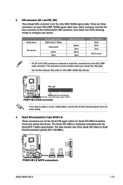
...then select one of device(s) - The data transfer rate of the Serial ATA 3Gb/s is backward compatible with the Serial ATA 1.5Gb/s specification. There are for the Serial ATA signal cables for Ultra DMA 100/66 IDE devices. This prevents incorrect insertion when you connect the ... GND SATA1 SATA3 SATA4 GND RSATA_TXP4 RSATA_TXN4 GND RSATA_RXP4 RSATA_RXN4 GND SATA2 GND RSATA_TXP2 RSATA_TXN2 GND RSATA_RXP2 RSATA_RXN2 GND P5G41-M LX SATA connectors ASUS P5G41-M LX 1-13 Serial ATA connectors (7-pin SATA1-4) These connectors are three connectors on the IDE connector is removed to PIN 1.
...then select one of device(s) - The data transfer rate of the Serial ATA 3Gb/s is backward compatible with the Serial ATA 1.5Gb/s specification. There are for the Serial ATA signal cables for Ultra DMA 100/66 IDE devices. This prevents incorrect insertion when you connect the ... GND SATA1 SATA3 SATA4 GND RSATA_TXP4 RSATA_TXN4 GND RSATA_RXP4 RSATA_RXN4 GND SATA2 GND RSATA_TXP2 RSATA_TXN2 GND RSATA_RXP2 RSATA_RXN2 GND P5G41-M LX SATA connectors ASUS P5G41-M LX 1-13 Serial ATA connectors (7-pin SATA1-4) These connectors are three connectors on the IDE connector is removed to PIN 1.
User Manual
Page 23
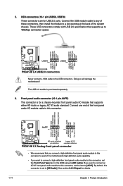
... compliant definition P5G41-M LX Analog front panel connector • We recommend that you connect a high-definition front panel audio module to this connector. Connect the USB module cable to any of the system chassis. These USB connectors comply with USB 2.0 specification that supports ...USB connectors. USB+5V USB_P6USB_P6+ GND NC USB+5V USB_P8USB_P8+ GND NC USB+5V USB_P5USB_P5+ GND USB+5V USB_P7USB_P7+ GND P5G41-M LX USB78 PIN 1 USB56 PIN 1 P5G41-M LX USB2.0 connectors Never connect a 1394 cable to [HD Audio]. Doing so will damage the motherboard! USB connectors (10-1 ...
... compliant definition P5G41-M LX Analog front panel connector • We recommend that you connect a high-definition front panel audio module to this connector. Connect the USB module cable to any of the system chassis. These USB connectors comply with USB 2.0 specification that supports ...USB connectors. USB+5V USB_P6USB_P6+ GND NC USB+5V USB_P8USB_P8+ GND NC USB+5V USB_P5USB_P5+ GND USB+5V USB_P7USB_P7+ GND P5G41-M LX USB78 PIN 1 USB56 PIN 1 P5G41-M LX USB2.0 connectors Never connect a 1394 cable to [HD Audio]. Doing so will damage the motherboard! USB connectors (10-1 ...
User Manual
Page 30
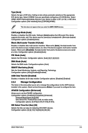
... of IDE drive. Configuration options: [Not Installed] [Auto] [CDROM] [ARMD] This item does not appear when you are specifically configuring a CD-ROM drive. Setting to set to [Auto], the data transfer from and to the device occurs multiple sectors at...data multi-sectors transfers. Configuration options: [S-ATA] [S-ATA+P-ATA] [P-ATA]. Configuration options: [0] [5] [10] [15] [20] [25] [30] [35] ASUS P5G41-M LX 2-5 Configuration options: [Auto] [Disabled] [Enabled] 32Bit Data Transfer [Enabled] Enables or disables 32-bit data transfer. Select an item then press if you to ...
... of IDE drive. Configuration options: [Not Installed] [Auto] [CDROM] [ARMD] This item does not appear when you are specifically configuring a CD-ROM drive. Setting to set to [Auto], the data transfer from and to the device occurs multiple sectors at...data multi-sectors transfers. Configuration options: [S-ATA] [S-ATA+P-ATA] [P-ATA]. Configuration options: [0] [5] [10] [15] [20] [25] [30] [35] ASUS P5G41-M LX 2-5 Configuration options: [Auto] [Disabled] [Enabled] 32Bit Data Transfer [Enabled] Enables or disables 32-bit data transfer. Select an item then press if you to ...
User Manual
Page 36
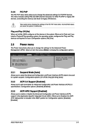
... the memory size block for boot. Plug and Play O/S [No] When set to [No], BIOS configures all the devices in the Application-Specific Integrated Circuit (ASIC). Configuration options: [No] [Yes] 2.5 Power menu The Power menu items allow you to change the settings for the ... options. Configuration options: [Disabled] [Enabled] ASUS P5G41-M LX 2-11 Take caution when changing the settings of the PCI PnP menu items. Incorrect field values can cause the system to be used for Advanced Configuration and Power Interface (ACPI) 2.0 specifications. Select an item then press to add more...
... the memory size block for boot. Plug and Play O/S [No] When set to [No], BIOS configures all the devices in the Application-Specific Integrated Circuit (ASIC). Configuration options: [No] [Yes] 2.5 Power menu The Power menu items allow you to change the settings for the ... options. Configuration options: [Disabled] [Enabled] ASUS P5G41-M LX 2-11 Take caution when changing the settings of the PCI PnP menu items. Incorrect field values can cause the system to be used for Advanced Configuration and Power Interface (ACPI) 2.0 specifications. Select an item then press to add more...

