User Manual
Page 3
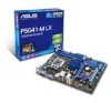
Contents Notices...v Safety information vi About this guide vii P5G41-M LX specifications summary viii Chapter 1: Product introduction 1.1 Before you proceed 1-1 1.2 Motherboard overview 1-2 1.2.1 Motherboard layout 1-2 1.2.2 Layout contents 1-2 1.3 Central Processing Unit (CPU 1-3 1.4 System memory 1-3 ... support 1-16 1.8.1 Installing an operating system 1-16 1.8.2 Support DVD information 1-16 Chapter 2: BIOS information 2.1 Managing and updating your BIOS 2-1 2.1.1 ASUS Update utility 2-1 2.1.2 ASUS EZ Flash 2 2-2 2.1.3 ASUS CrashFree BIOS 2-3 2.2 BIOS setup program 2-3 iii
Contents Notices...v Safety information vi About this guide vii P5G41-M LX specifications summary viii Chapter 1: Product introduction 1.1 Before you proceed 1-1 1.2 Motherboard overview 1-2 1.2.1 Motherboard layout 1-2 1.2.2 Layout contents 1-2 1.3 Central Processing Unit (CPU 1-3 1.4 System memory 1-3 ... support 1-16 1.8.1 Installing an operating system 1-16 1.8.2 Support DVD information 1-16 Chapter 2: BIOS information 2.1 Managing and updating your BIOS 2-1 2.1.1 ASUS Update utility 2-1 2.1.2 ASUS EZ Flash 2 2-2 2.1.3 ASUS CrashFree BIOS 2-3 2.2 BIOS setup program 2-3 iii
User Manual
Page 8
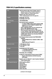
...USB 2.0/1.1 ports (4 ports at mid-board, 4 ports at back panel) ASUS CrashFree BIOS 3 ASUS Q-Fan ASUS EZ Flash 2 ASUS MyLogo 2 ASUS AI NET 2 ASUS Turbo Key (continued on the next page) viii P5G41-M LX specifications summary CPU Chipset Front Side Bus Memory Graphics Expansion slots Storage LAN ...Audio USB ASUS special features LGA775 socket for Intel® Core™2 Quad ...
...USB 2.0/1.1 ports (4 ports at mid-board, 4 ports at back panel) ASUS CrashFree BIOS 3 ASUS Q-Fan ASUS EZ Flash 2 ASUS MyLogo 2 ASUS AI NET 2 ASUS Turbo Key (continued on the next page) viii P5G41-M LX specifications summary CPU Chipset Front Side Bus Memory Graphics Expansion slots Storage LAN ...Audio USB ASUS special features LGA775 socket for Intel® Core™2 Quad ...
User Manual
Page 9
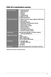
P5G41-M LX specifications summary Back panel I/O ports Internal I/O connectors BIOS features Support DVD contents Accessories Form factor 1 x PS/2 keyboard port 1 x PS/2 mouse port 1 x COM port 1 x VGA port 1 x ...-pin EATX power connector 1 x 4-pin ATX 12V power connector 8Mb Flash ROM, AMI BIOS, PnP, DMI 2.0, WfM 2.0, ACPI v2.0a, SM BIOS v2.5 Drivers ASUS PC Probe II ASUS LiveUpdate Utility Anti-virus software (OEM version) 2 x Serial ATA cables 1 x UltraDMA 100/66 cable 1 x I/O shield User Manual MicroATX form factor: 9.6 in x 7.2 in (24...
P5G41-M LX specifications summary Back panel I/O ports Internal I/O connectors BIOS features Support DVD contents Accessories Form factor 1 x PS/2 keyboard port 1 x PS/2 mouse port 1 x COM port 1 x VGA port 1 x ...-pin EATX power connector 1 x 4-pin ATX 12V power connector 8Mb Flash ROM, AMI BIOS, PnP, DMI 2.0, WfM 2.0, ACPI v2.0a, SM BIOS v2.5 Drivers ASUS PC Probe II ASUS LiveUpdate Utility Anti-virus software (OEM version) 2 x Serial ATA cables 1 x UltraDMA 100/66 cable 1 x I/O shield User Manual MicroATX form factor: 9.6 in x 7.2 in (24...
User Manual
Page 10
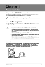
... the component. • Before you install or remove any component, ensure that lights up to page ix for buying an ASUS® P5G41-M LX motherboard! SB_PWR P5G41-M LX ON OFF Standby Power Powered Off P5G41-M LX Onboard LED ASUS P5G41-M LX 1-1 Before you start installing the motherboard, and hardware devices on it on them. • Whenever you install motherboard components...
... the component. • Before you install or remove any component, ensure that lights up to page ix for buying an ASUS® P5G41-M LX motherboard! SB_PWR P5G41-M LX ON OFF Standby Power Powered Off P5G41-M LX Onboard LED ASUS P5G41-M LX 1-1 Before you start installing the motherboard, and hardware devices on it on them. • Whenever you install motherboard components...

User Manual
Page 12
ASUS will process Return Merchandise Authorization (RMA) requests only if the motherboard comes with the cap on the socket and the socket contacts are not bent. ... the cap after installing the motherboard. The figure illustrates the location of the DDR2 DIMM sockets: DIMM_A1 DIMM_B1 Channel Channel A Channel B P5G41-M LX P5G41-M LX 240-pin DDR2 DIMM sockets Sockets DIMM_A1 DIMM_B1 ASUS P5G41-M LX 1-3 Contact your retailer immediately if the PnP cap is missing, or if you see any damage to the socket contacts resulting...
ASUS will process Return Merchandise Authorization (RMA) requests only if the motherboard comes with the cap on the socket and the socket contacts are not bent. ... the cap after installing the motherboard. The figure illustrates the location of the DDR2 DIMM sockets: DIMM_A1 DIMM_B1 Channel Channel A Channel B P5G41-M LX P5G41-M LX 240-pin DDR2 DIMM sockets Sockets DIMM_A1 DIMM_B1 ASUS P5G41-M LX 1-3 Contact your retailer immediately if the PnP cap is missing, or if you see any damage to the socket contacts resulting...
User Manual
Page 14
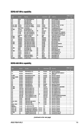
...-Sink Package DS Heat-Sink Package SS HY5PS12821CFP-S5 DS HY5PS12821CFPS5 • • • • • • • • • (continued on the next page) ASUS P5G41-M LX 1-5 NT5TU64M8BE-3C72155700CP Heat-Sink Package Heat-Sink Package Heat-Sink Package D2 64M8CCF 0815 C7173S Heat-Sink Package PG 64M8-800 0750 A3R12E3GEF633ACAOY K4T2G084QA-HCE6...
...-Sink Package DS Heat-Sink Package SS HY5PS12821CFP-S5 DS HY5PS12821CFPS5 • • • • • • • • • (continued on the next page) ASUS P5G41-M LX 1-5 NT5TU64M8BE-3C72155700CP Heat-Sink Package Heat-Sink Package Heat-Sink Package D2 64M8CCF 0815 C7173S Heat-Sink Package PG 64M8-800 0750 A3R12E3GEF633ACAOY K4T2G084QA-HCE6...
User Manual
Page 16
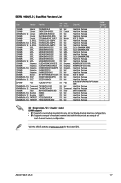
Single-sided / DS - Visit the ASUS website at www.asus.com for the latest QVL. ASUS P5G41-M LX 1-7 support A* B* Heat-Sink Package •• Heat-Sink Package •• Heat-Sink Package •• Heat-Sink Package •• 9CE12 D9JKH •• ...
Single-sided / DS - Visit the ASUS website at www.asus.com for the latest QVL. ASUS P5G41-M LX 1-7 support A* B* Heat-Sink Package •• Heat-Sink Package •• Heat-Sink Package •• Heat-Sink Package •• 9CE12 D9JKH •• ...
User Manual
Page 18
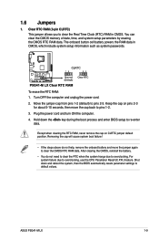
... boot process and enter BIOS setup to clear the Real Time Clock (RTC) RAM in CMOS, which include system setup information such as system passwords. ASUS P5G41-M LX 1-9 Except when clearing the RTC RAM, never remove the cap on pins 2-3 for about 5-10 seconds, then move the jumper again to default values. You...
... boot process and enter BIOS setup to clear the Real Time Clock (RTC) RAM in CMOS, which include system setup information such as system passwords. ASUS P5G41-M LX 1-9 Except when clearing the RTC RAM, never remove the cap on pins 2-3 for about 5-10 seconds, then move the jumper again to default values. You...
User Manual
Page 20
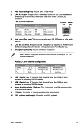
... port (light blue). This port connects a microphone. Video Graphics Adapter (VGA) port. This 15-pin port is for a VGA monitor or other VGA-compatible devices. 9. ASUS P5G41-M LX 1-11 Microphone port (pink). Audio 2, 4, or 6-channel configuration Port Light Blue Lime Pink Headset 2-channel Line In Line Out Mic In 4-channel Rear Speaker Out...
... port (light blue). This port connects a microphone. Video Graphics Adapter (VGA) port. This 15-pin port is for a VGA monitor or other VGA-compatible devices. 9. ASUS P5G41-M LX 1-11 Microphone port (pink). Audio 2, 4, or 6-channel configuration Port Light Blue Lime Pink Headset 2-channel Line In Line Out Mic In 4-channel Rear Speaker Out...
User Manual
Page 21
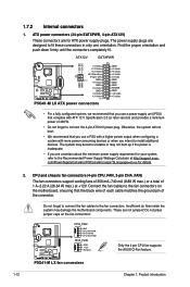
...pin CPU_FAN, 3-pin CHA_FAN) The fan connectors support cooling fans of 350 mA~740 mA (8.88 W max.) or a total of the connector. P5G41-M LX fan connectors 1-12 Chapter 1: Product introduction com/PowerSupplyCalculator/PSCalculator.aspx?SLanguage=en-us for ATX power supply plugs. Do not forget to connect the fan...the black wire of each cable matches the ground pin of 1 A~2.22 A (26.64 W max.) at http://support.asus. These are designed to install additional devices. P5G41-M LX CPU_FAN GND CPU FAN PWR CPU FAN IN CPU FAN PWM CHA_FAN GND +12V Rotation Only the 4-pin CPU fan supports the...
...pin CPU_FAN, 3-pin CHA_FAN) The fan connectors support cooling fans of 350 mA~740 mA (8.88 W max.) or a total of the connector. P5G41-M LX fan connectors 1-12 Chapter 1: Product introduction com/PowerSupplyCalculator/PSCalculator.aspx?SLanguage=en-us for ATX power supply plugs. Do not forget to connect the fan...the black wire of each cable matches the ground pin of 1 A~2.22 A (26.64 W max.) at http://support.asus. These are designed to install additional devices. P5G41-M LX CPU_FAN GND CPU FAN PWR CPU FAN IN CPU FAN PWM CHA_FAN GND +12V Rotation Only the 4-pin CPU fan supports the...
User Manual
Page 22
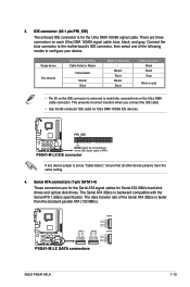
... RSATA_TXN3 RSATA_TXP3 GND SATA1 SATA3 SATA4 GND RSATA_TXP4 RSATA_TXN4 GND RSATA_RXP4 RSATA_RXN4 GND SATA2 GND RSATA_TXP2 RSATA_TXN2 GND RSATA_RXP2 RSATA_RXN2 GND P5G41-M LX SATA connectors ASUS P5G41-M LX 1-13 3. This prevents incorrect insertion when you connect the IDE cable. • Use the 80-conductor IDE cable ... PRI_IDE) The onboard IDE connector is set as "Cable-Select," ensure that all other device jumpers have the same setting. 4. PRI_IDE P5G41-M LX PIN1 NOTE:Orient the red markings on each Ultra DMA 100/66 signal cable: blue, black, and gray. The Serial ATA 3Gb/s...
... RSATA_TXN3 RSATA_TXP3 GND SATA1 SATA3 SATA4 GND RSATA_TXP4 RSATA_TXN4 GND RSATA_RXP4 RSATA_RXN4 GND SATA2 GND RSATA_TXP2 RSATA_TXN2 GND RSATA_RXP2 RSATA_RXN2 GND P5G41-M LX SATA connectors ASUS P5G41-M LX 1-13 3. This prevents incorrect insertion when you connect the IDE cable. • Use the 80-conductor IDE cable ... PRI_IDE) The onboard IDE connector is set as "Cable-Select," ensure that all other device jumpers have the same setting. 4. PRI_IDE P5G41-M LX PIN1 NOTE:Orient the red markings on each Ultra DMA 100/66 signal cable: blue, black, and gray. The Serial ATA 3Gb/s...
User Manual
Page 24
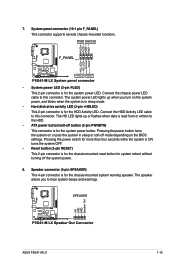
... power button. System panel connector (10-1 pin F_PANEL) This connector supports several chassis-mounted functions. PLED PWR BTN F_PANEL PIN 1 P5G41-M LX +HDLED RESET P5G41-M LX System panel connector • System power LED (2-pin PLED) This 2-pin connector is for the chassis-mounted reset button for the... or soft-off button (2-pin PWRBTN) This connector is for the chassis-mounted system warning speaker. SPEAKER P5G41-M LX PIN 1 P5G41-M LX Speaker Out Connector +5V GND GND Speaker Out ASUS P5G41-M LX 1-15 The HD LED lights up when you to the HDD. • ATX power button/soft-off...
... power button. System panel connector (10-1 pin F_PANEL) This connector supports several chassis-mounted functions. PLED PWR BTN F_PANEL PIN 1 P5G41-M LX +HDLED RESET P5G41-M LX System panel connector • System power LED (2-pin PLED) This 2-pin connector is for the chassis-mounted reset button for the... or soft-off button (2-pin PWRBTN) This connector is for the chassis-mounted system warning speaker. SPEAKER P5G41-M LX PIN 1 P5G41-M LX Speaker Out Connector +5V GND GND Speaker Out ASUS P5G41-M LX 1-15 The HD LED lights up when you to the HDD. • ATX power button/soft-off...
User Manual
Page 26
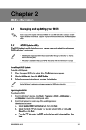
... that allows you to avoid network traffic, or click Auto Select then click Next. ASUS P5G41-M LX 2-1 Follow the onscreen instructions to launch the ASUS Update utility. 2. Updating the BIOS To update the BIOS: 1. Click the Utilities tab, then click ASUS Update. 3. Chapter 2 BIOS information 2.1 Managing and updating your BIOS Save a copy of the updating...
... that allows you to avoid network traffic, or click Auto Select then click Next. ASUS P5G41-M LX 2-1 Follow the onscreen instructions to launch the ASUS Update utility. 2. Updating the BIOS To update the BIOS: 1. Click the Utilities tab, then click ASUS Update. 3. Chapter 2 BIOS information 2.1 Managing and updating your BIOS Save a copy of the updating...
User Manual
Page 28
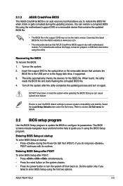
... POST To enter BIOS Setup after the utility completes the updating process and turn the system off then back on. ASUS P5G41-M LX 2-3 Download the latest BIOS file from the ASUS website at startup: • Press during the updating process. The utility automatically checks the devices for details. 2.2 ...guide you failed to enter BIOS Setup using this utility. Turn on again. Entering BIOS Setup at startup To enter BIOS Setup at www.asus.com. • The removable devices that contains the updated BIOS file. • The BIOS file in using the motherboard support DVD or...
... POST To enter BIOS Setup after the utility completes the updating process and turn the system off then back on. ASUS P5G41-M LX 2-3 Download the latest BIOS file from the ASUS website at startup: • Press during the updating process. The utility automatically checks the devices for details. 2.2 ...guide you failed to enter BIOS Setup using this utility. Turn on again. Entering BIOS Setup at startup To enter BIOS Setup at www.asus.com. • The removable devices that contains the updated BIOS file. • The BIOS file in using the motherboard support DVD or...
User Manual
Page 30
... devices installed in this mode, and if the device was not previously formatted with LBA mode disabled. Configuration options: [0] [5] [10] [15] [20] [25] [30] [35] ASUS P5G41-M LX 2-5 When set to [Auto], the data transfer from and to the device occurs one sector at a time if the device supports multi-sector transfer feature...
... devices installed in this mode, and if the device was not previously formatted with LBA mode disabled. Configuration options: [0] [5] [10] [15] [20] [25] [30] [35] ASUS P5G41-M LX 2-5 When set to [Auto], the data transfer from and to the device occurs one sector at a time if the device supports multi-sector transfer feature...
User Manual
Page 32
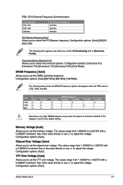
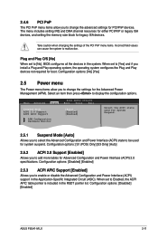
If this happens, revert to adjust the voltage. to the default setting. Key in the value directly or use +/- Configuration options: [Auto] ASUS P5G41-M LX 2-7 Key in the value directly or use +/- to adjust the voltage. to adjust the voltage. Configuration options: [Auto] [667 MHz] [800 MHz] [1067MHz] The following ...
If this happens, revert to adjust the voltage. to the default setting. Key in the value directly or use +/- Configuration options: [Auto] ASUS P5G41-M LX 2-7 Key in the value directly or use +/- to adjust the voltage. to adjust the voltage. Configuration options: [Auto] [667 MHz] [800 MHz] [1067MHz] The following ...
User Manual
Page 34
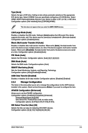
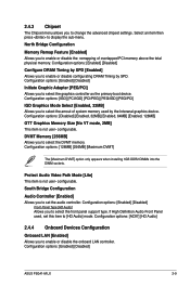
... memory above the total physical memory. North Bridge Configuration Memory Remap Feature [Enabled] Allows you to change the advanced chipset settings. Configuration options: [Enabled] [Disabled] ASUS P5G41-M LX 2-9 2.4.3 Chipset The Chipset menu allows you to enable or disable the remapping of system memory used , set the audio controller. South Bridge Configuration Audio Controller...
... memory above the total physical memory. North Bridge Configuration Memory Remap Feature [Enabled] Allows you to change the advanced chipset settings. Configuration options: [Enabled] [Disabled] ASUS P5G41-M LX 2-9 2.4.3 Chipset The Chipset menu allows you to enable or disable the remapping of system memory used , set the audio controller. South Bridge Configuration Audio Controller...
User Manual
Page 36
...] Allows you install a Plug and Play operating system, the operating system configures the Plug and Play devices not required for boot. Configuration options: [Disabled] [Enabled] ASUS P5G41-M LX 2-11 When set to be used for legacy ISA devices. The menu includes setting IRQ and DMA channel resources for either PCI/PnP or legacy...
...] Allows you install a Plug and Play operating system, the operating system configures the Plug and Play devices not required for boot. Configuration options: [Disabled] [Enabled] ASUS P5G41-M LX 2-11 When set to be used for legacy ISA devices. The menu includes setting IRQ and DMA channel resources for either PCI/PnP or legacy...
User Manual
Page 38
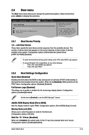
.... Configuration options: [Disabled] [Enabled] Set this item allows the BIOS to skip some power on the number of the following: • Press when ASUS Logo appears. • Press after POST. 2.6.2 Boot Settings Configuration Quick Boot [Enabled] Enabling this item to [Enabled] to display the sub-menu. ... A virtual floppy disk drive (Floppy Drive B: ) may appear when you to boot the system. Configuration options: [Disabled] [Enabled] ASUS P5G41-M LX 2-13 The number of device items that appears on the screen depends on self tests (POST) while booting to decrease the time needed ...
.... Configuration options: [Disabled] [Enabled] Set this item allows the BIOS to skip some power on the number of the following: • Press when ASUS Logo appears. • Press after POST. 2.6.2 Boot Settings Configuration Quick Boot [Enabled] Enabling this item to [Enabled] to display the sub-menu. ... A virtual floppy disk drive (Floppy Drive B: ) may appear when you to boot the system. Configuration options: [Disabled] [Enabled] ASUS P5G41-M LX 2-13 The number of device items that appears on the screen depends on self tests (POST) while booting to decrease the time needed ...
User Manual
Page 40
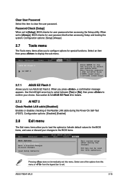
... menu The Exit menu items allow you press , a confirmation message appears. Select+FFEEFFEo-11Sn11Sn0Ct0CeeorSSCGSEf eeheaxtSSGGSEhllanvieeoeaxeeeneetllnviccgroeeteettteaapccorlntttaaioSIOdSlnnctpHSIudsreteEctbHemilxfre-eEreopioemslxnntmecpinrtteheisn ASUS P5G41-M LX 2-15 Password Check [Setup] When set to load the optimal or failsafe default values for user password ...menu or from the legend bar to clear the user password. Select an item then press to run ASUS EZ Flash 2. When you to [Setup], BIOS checks for special functions. menu. Configuration options: [Setup...
... menu The Exit menu items allow you press , a confirmation message appears. Select+FFEEFFEo-11Sn11Sn0Ct0CeeorSSCGSEf eeheaxtSSGGSEhllanvieeoeaxeeeneetllnviccgroeeteettteaapccorlntttaaioSIOdSlnnctpHSIudsreteEctbHemilxfre-eEreopioemslxnntmecpinrtteheisn ASUS P5G41-M LX 2-15 Password Check [Setup] When set to load the optimal or failsafe default values for user password ...menu or from the legend bar to clear the user password. Select an item then press to run ASUS EZ Flash 2. When you to [Setup], BIOS checks for special functions. menu. Configuration options: [Setup...


