
User Manual
Page 3
... Safety information vii P5G41-M EVO specifications summary viii Chapter 1: Product introduction 1.1 Before you proceed 1-1 1.2 Motherboard overview 1-2 1.2.1 Motherboard layout 1-2 1.2.2 Layout contents 1-2 1.3 Central Processing Unit (CPU 1-3 1.4 System memory 1-3 1.4.1 Overview 1-3 1.4.2 Memory configurations 1-4 1.5 Expansion slots 1-7 1.5.1 Installing an expansion card 1-7 1.5.2 Configuring an expansion card 1-8 1.5.3 PCI slots 1-8 1.5.4 PCI Express x16 slot 1-8 1.6 Jumpers 1-8 1.7 Connectors 1-10 1.7.1 Rear panel ports 1-10 1.7.2 Internal connectors...
... Safety information vii P5G41-M EVO specifications summary viii Chapter 1: Product introduction 1.1 Before you proceed 1-1 1.2 Motherboard overview 1-2 1.2.1 Motherboard layout 1-2 1.2.2 Layout contents 1-2 1.3 Central Processing Unit (CPU 1-3 1.4 System memory 1-3 1.4.1 Overview 1-3 1.4.2 Memory configurations 1-4 1.5 Expansion slots 1-7 1.5.1 Installing an expansion card 1-7 1.5.2 Configuring an expansion card 1-8 1.5.3 PCI slots 1-8 1.5.4 PCI Express x16 slot 1-8 1.6 Jumpers 1-8 1.7 Connectors 1-10 1.7.1 Rear panel ports 1-10 1.7.2 Internal connectors...

User Manual
Page 4
... Date 2-5 2.3.3 Legacy Diskette A 2-5 2.3.4 Primary IDE Master/Slave and SATA 1-4 2-5 2.3.6 System Information 2-6 2.3.5 Storage Configuration 2-6 2.4 Advanced menu 2-7 2.4.1 CPU Configuration 2-7 2.4.2 Chipset 2-8 2.4.3 Onboard Devices Configuration 2-9 2.4.4 USB Configuration 2-9 2.4.5 PCI PnP 2-10 2.5 Power menu 2-11 2.5.1 Suspend Mode 2-11 2.5.2 ACPI 2.0 Support 2-11 2.5.3 ACPI APIC Support 2-11 2.5.4 APM Configuration 2-11 2.5.5 Hardware Monitor 2-12 2.6 Boot menu 2-13 2.6.1 Boot Device Priority...
... Date 2-5 2.3.3 Legacy Diskette A 2-5 2.3.4 Primary IDE Master/Slave and SATA 1-4 2-5 2.3.6 System Information 2-6 2.3.5 Storage Configuration 2-6 2.4 Advanced menu 2-7 2.4.1 CPU Configuration 2-7 2.4.2 Chipset 2-8 2.4.3 Onboard Devices Configuration 2-9 2.4.4 USB Configuration 2-9 2.4.5 PCI PnP 2-10 2.5 Power menu 2-11 2.5.1 Suspend Mode 2-11 2.5.2 ACPI 2.0 Support 2-11 2.5.3 ACPI APIC Support 2-11 2.5.4 APM Configuration 2-11 2.5.5 Hardware Monitor 2-12 2.6 Boot menu 2-13 2.6.1 Boot Device Priority...

User Manual
Page 12
... 18. CHA_FAN LGA775 USB34 USBPW1-4 LAN1_USB12 RTL 8112L COM1 AUDIO CHASSIS ICS 9LPRS441 PCIEX16 Intel® G41 Super I/O PCI1 P5G41-M EVO PCI2 VIA VT1708S CD AAFP SPDIF_OUT PCI3 FLOPPY LPT Lithium Cell CMOS Power Intel® ICH7 SATA4 SATA3 SATA2 SATA1 USB56 ...pin USBPW1-4, USBPW5-8) 1-9 12. Intel CPU socket 1-3 16 Floppy disk drive connector (34-1 pin FLOPPY) 1-17 7. System panel connector (10-1 pin F_PANEL) 1-15 19. 1.2 1.2.1 Motherboard overview Motherboard layout Ensure that you install the motherboard into the holes indicated by circles to secure...
... 18. CHA_FAN LGA775 USB34 USBPW1-4 LAN1_USB12 RTL 8112L COM1 AUDIO CHASSIS ICS 9LPRS441 PCIEX16 Intel® G41 Super I/O PCI1 P5G41-M EVO PCI2 VIA VT1708S CD AAFP SPDIF_OUT PCI3 FLOPPY LPT Lithium Cell CMOS Power Intel® ICH7 SATA4 SATA3 SATA2 SATA1 USB56 ...pin USBPW1-4, USBPW5-8) 1-9 12. Intel CPU socket 1-3 16 Floppy disk drive connector (34-1 pin FLOPPY) 1-17 7. System panel connector (10-1 pin F_PANEL) 1-15 19. 1.2 1.2.1 Motherboard overview Motherboard layout Ensure that you install the motherboard into the holes indicated by circles to secure...
User Manual
Page 18
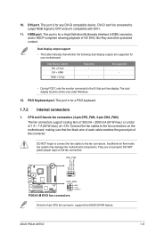
...as LAN cards, SCSI cards, USB cards, and other cards that comply with the PCI Express specifications. 1.6 Jumpers 1. CLRTC 12 23 P5G41-M EVO Normal (Default) Clear RTC P5G41-M EVO Clear RTC RAM To erase the RTC RAM: 1. Keep the cap on the system and change the necessary BIOS settings, if any. Install... the software drivers for about 5-10 seconds, then move the cap back to the card. 3. Hold down the key during the boot process...
...as LAN cards, SCSI cards, USB cards, and other cards that comply with the PCI Express specifications. 1.6 Jumpers 1. CLRTC 12 23 P5G41-M EVO Normal (Default) Clear RTC P5G41-M EVO Clear RTC RAM To erase the RTC RAM: 1. Keep the cap on the system and change the necessary BIOS settings, if any. Install... the software drivers for about 5-10 seconds, then move the cap back to the card. 3. Hold down the key during the boot process...

User Manual
Page 20
... 4. This port connects to USB 2.0/1.1 devices. 9. Refer to a microphone. COM port. 1.7 Connectors 1.7.1 Rear panel ports 1 2 3 4 56 12 11 10 9 8 7 1. This port is for a PS/2 mouse. 2. LAN port LED indications ACT/LINK LED SPEED LED ACT/LINK SPEED LED LED Status Description Status... Description OFF No link OFF 10 Mbps connection ORANGE Linked ORANGE 100 Mbps connection BLINKING Data activity GREEN 1 Gbps connection LAN port 5. This port connects ...
... 4. This port connects to USB 2.0/1.1 devices. 9. Refer to a microphone. COM port. 1.7 Connectors 1.7.1 Rear panel ports 1 2 3 4 56 12 11 10 9 8 7 1. This port is for a PS/2 mouse. 2. LAN port LED indications ACT/LINK LED SPEED LED ACT/LINK SPEED LED LED Status Description Status... Description OFF No link OFF 10 Mbps connection ORANGE Linked ORANGE 100 Mbps connection BLINKING Data activity GREEN 1 Gbps connection LAN port 5. This port connects ...
User Manual
Page 21
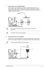
... the fan connectors. The dual display function works only under Windows. 12. Connect the fan cables to the D-Sub port has display. ASUS P5G41-M EVO 1-11 PS/2 Keyboard port. Insufficient air flow inside the system may damage the motherboard components. This port is for your motherboard: Dual ... support • This table indicates that the black wire of each cable matches the ground pin of 1 A ~ 7 A (84 W max.) at +12V. 10. CPU and Chassis fan connectors (4-pin CPU_FAN, 3-pin CHA_FAN) The fan connectors support cooling fans of 350 mA ~ 2000 mA (24 W max.) or a total...
... the fan connectors. The dual display function works only under Windows. 12. Connect the fan cables to the D-Sub port has display. ASUS P5G41-M EVO 1-11 PS/2 Keyboard port. Insufficient air flow inside the system may damage the motherboard components. This port is for your motherboard: Dual ... support • This table indicates that the black wire of each cable matches the ground pin of 1 A ~ 7 A (84 W max.) at +12V. 10. CPU and Chassis fan connectors (4-pin CPU_FAN, 3-pin CHA_FAN) The fan connectors support cooling fans of 350 mA ~ 2000 mA (24 W max.) or a total...
User Manual
Page 23
...) connector ASUS P5G41-M EVO 1-13 USB+5V USB_P8USB_P8+ GND NC USB+5V USB_P6USB_P6+ GND NC P5G41-M EVO USB56 PIN 1 USB78 PIN 1 USB+5V USB_P7USB_P7+ GND USB+5V USB_P5USB_P5+ GND P5G41-M EVO USB2.0 connectors Never connect a 1394 cable to 480Mbps connection speed. Doing so will damage the motherboard! The serial port bracket (COM1) is purchased separately. 5. USB connectors (10...
...) connector ASUS P5G41-M EVO 1-13 USB+5V USB_P8USB_P8+ GND NC USB+5V USB_P6USB_P6+ GND NC P5G41-M EVO USB56 PIN 1 USB78 PIN 1 USB+5V USB_P7USB_P7+ GND USB+5V USB_P5USB_P5+ GND P5G41-M EVO USB2.0 connectors Never connect a 1394 cable to 480Mbps connection speed. Doing so will damage the motherboard! The serial port bracket (COM1) is purchased separately. 5. USB connectors (10...
User Manual
Page 25
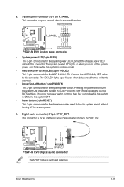
... up when you turn on the system power, and blinks when the system is in SLEEP or SOFT-OFF mode depending on the BIOS settings. ASUS P5G41-M EVO 1-15 Connect the chassis power LED cable to the HDD. • Power/Soft-off the system power. 9. Digital audio connector (4-1 pin SPDIF_OUT)... the system in sleep mode. • Hard disk drive activity LED (2-pin +HDLED) This 2-pin connector is purchased separately. 8. System panel connector (10-1 pin F_PANEL) This connector supports several chassis-mounted functions. PWR LED PWR BTN PLED+ PLEDPWR GND F_PANEL PIN 1 IDE_LED+ IDE_LED-
... up when you turn on the system power, and blinks when the system is in SLEEP or SOFT-OFF mode depending on the BIOS settings. ASUS P5G41-M EVO 1-15 Connect the chassis power LED cable to the HDD. • Power/Soft-off the system power. 9. Digital audio connector (4-1 pin SPDIF_OUT)... the system in sleep mode. • Hard disk drive activity LED (2-pin +HDLED) This 2-pin connector is purchased separately. 8. System panel connector (10-1 pin F_PANEL) This connector supports several chassis-mounted functions. PWR LED PWR BTN PLED+ PLEDPWR GND F_PANEL PIN 1 IDE_LED+ IDE_LED-
User Manual
Page 26
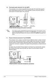
... 1 MIC2 MICPWR Line out_R NC Line out_L PORT1 L PORT1 R PORT2 R SENSE_SEND PORT2 L P5G41-M EVO HD-audio-compliant Legacy AC'97 pin definition compliant definition P5G41-M EVO Analog front panel connector If you want to connect an AC97 front panel audio module to this connector.... The signal is for a chassis-mounted intrusion detection sensor or switch. If you intend to [HD Audio]. CHASSIS P5G41-M EVO GND Chassis Signal +5VSB_MB P5G41-M EVO Chassis intrusion connector 1-16 Chapter 1: Product introduction The chassis intrusion sensor or switch sends a high-level signal to [...
... 1 MIC2 MICPWR Line out_R NC Line out_L PORT1 L PORT1 R PORT2 R SENSE_SEND PORT2 L P5G41-M EVO HD-audio-compliant Legacy AC'97 pin definition compliant definition P5G41-M EVO Analog front panel connector If you want to connect an AC97 front panel audio module to this connector.... The signal is for a chassis-mounted intrusion detection sensor or switch. If you intend to [HD Audio]. CHASSIS P5G41-M EVO GND Chassis Signal +5VSB_MB P5G41-M EVO Chassis intrusion connector 1-16 Chapter 1: Product introduction The chassis intrusion sensor or switch sends a high-level signal to [...

User Manual
Page 27
...IE1394_1 TPA1GND TPB1+12V GND P5G41-M EVO PIN 1 TPA1+ GND TPB1+ +12V P5G41-M EVO IEEE 1394a Connector 13. Floppy disk drive connector (34-1 pin FLOPPY) This connector is for the provided floppy disk drive (FDD) signal cable. IEEE 1394a connector (10-1 pin IE1394_1) This port...P5G41-M EVO PIN1 NOTE:Orient the red markings on the connector is the parallel port interface on IBM PC-compatible computers. LPT AFD ERR# INIT# SLIN# GND GND GND GND GND GND GND GND PIN 1 STB# PD0 PD1 PD2 PD3 PD4 PD5 PD6 PD7 ACK# BUSY PE SLCT P5G41-M EVO P5G41-M EVO Parallel Port Connector ASUS P5G41-M EVO...
...IE1394_1 TPA1GND TPB1+12V GND P5G41-M EVO PIN 1 TPA1+ GND TPB1+ +12V P5G41-M EVO IEEE 1394a Connector 13. Floppy disk drive connector (34-1 pin FLOPPY) This connector is for the provided floppy disk drive (FDD) signal cable. IEEE 1394a connector (10-1 pin IE1394_1) This port...P5G41-M EVO PIN1 NOTE:Orient the red markings on the connector is the parallel port interface on IBM PC-compatible computers. LPT AFD ERR# INIT# SLIN# GND GND GND GND GND GND GND GND PIN 1 STB# PD0 PD1 PD2 PD3 PD4 PD5 PD6 PD7 ACK# BUSY PE SLCT P5G41-M EVO P5G41-M EVO Parallel Port Connector ASUS P5G41-M EVO...
User Manual
Page 30
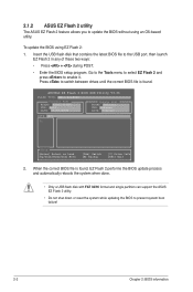
....36 FLASH TYPE: MXIC 25L8005 Current ROM BOARD: P5G41-M-EVO VER: 0203 DATE: 07/10/2009 Update ROM BOARD: Unknown VER: Unknown DATE: Unknown PATH: A:\ A: Note [Enter] Select or Load [Up/Down/Home/End] Move [Tab] Switch [B] Backup [V] Drive Info [ESC] Exit 2. 2.1.2 ASUS EZ Flash 2 utility The ASUS EZ Flash 2 feature allows you to update...
....36 FLASH TYPE: MXIC 25L8005 Current ROM BOARD: P5G41-M-EVO VER: 0203 DATE: 07/10/2009 Update ROM BOARD: Unknown VER: Unknown DATE: Unknown PATH: A:\ A: Note [Enter] Select or Load [Up/Down/Home/End] Move [Tab] Switch [B] Backup [V] Drive Info [ESC] Exit 2. 2.1.2 ASUS EZ Flash 2 utility The ASUS EZ Flash 2 feature allows you to update...

User Manual
Page 34
...] Selects the time out value for the SATA devices installed in this menu allow you set the ATA/IDE Configuration item to [Compitable]. Configuration options: [0] [5] [10] [15] [20] [25] [30] [35] 2.3.6 System Information This menu gives you set the ATA/IDE Configuration item to set the ATA/IDE configuration. ATA/IDE...
...] Selects the time out value for the SATA devices installed in this menu allow you set the ATA/IDE Configuration item to [Compitable]. Configuration options: [0] [5] [10] [15] [20] [25] [30] [35] 2.3.6 System Information This menu gives you set the ATA/IDE Configuration item to set the ATA/IDE configuration. ATA/IDE...

User Manual
Page 38
... you to enable or disable support for Legacy USB storage devices, including USB flash drives and USB hard drives. Configuration options: [No] [Yes] 2-10 Chapter 2: BIOS information Configuration options: [Enabled] [Disabled] Legacy USB Support [Auto] Allows you to set the maximum time that the BIOS waits for...devices. Plug and Play O/S [No] When set to malfunction. If no USB device is detected, the legacy USB support is disabled. Configuration options: [10 Sec] [20 Sec] [30 Sec] [40 Sec] Emulation Type [Auto] Allows you to disable or enable the USB functions. Take caution when ...
... you to enable or disable support for Legacy USB storage devices, including USB flash drives and USB hard drives. Configuration options: [No] [Yes] 2-10 Chapter 2: BIOS information Configuration options: [Enabled] [Disabled] Legacy USB Support [Auto] Allows you to set the maximum time that the BIOS waits for...devices. Plug and Play O/S [No] When set to malfunction. If no USB device is detected, the legacy USB support is disabled. Configuration options: [10 Sec] [20 Sec] [30 Sec] [40 Sec] Emulation Type [Auto] Allows you to disable or enable the USB functions. Take caution when ...


