User Guide
Page 3
... guide ix Typography ix P5CR-VM specifications summary x Chapter 1: Product introduction 1.1 Welcome 1-1 1.2 Package contents 1-1 1.3 Special features 1-2 1.3.1 Product highlights 1-2 1.3.2 Innovative ASUS features 1-4 Chapter 2: Hardware information 2.1 Before you proceed 2-1 2.2 Motherboard overview 2-2 2.2.1 Placement direction 2-2 2.2.2 Screw holes 2-2 2.2.3 Motherboard layout 2-3 2.2.4 Layout contents 2-4 2.3 Central Processing Unit (CPU 2-6 2.3.1 Installing the CPU 2-6 2.3.2 Installing the CPU heatsink and fan 2-9 2.3.3 Uninstalling the CPU heatsink and fan 2-11...
... guide ix Typography ix P5CR-VM specifications summary x Chapter 1: Product introduction 1.1 Welcome 1-1 1.2 Package contents 1-1 1.3 Special features 1-2 1.3.1 Product highlights 1-2 1.3.2 Innovative ASUS features 1-4 Chapter 2: Hardware information 2.1 Before you proceed 2-1 2.2 Motherboard overview 2-2 2.2.1 Placement direction 2-2 2.2.2 Screw holes 2-2 2.2.3 Motherboard layout 2-3 2.2.4 Layout contents 2-4 2.3 Central Processing Unit (CPU 2-6 2.3.1 Installing the CPU 2-6 2.3.2 Installing the CPU heatsink and fan 2-9 2.3.3 Uninstalling the CPU heatsink and fan 2-11...

User Guide
Page 5
Contents 4.4 Advanced menu 4-19 4.4.1 USB Configuration 4-19 4.4.2 MPS Configuration 4-20 4.4.3 Remote Access Configuration 4-21 4.4.4 CPU Configuration 4-22 4.4.5 Chipset 4-24 4.4.6 Onboard Devices Configuration 4-26 4.4.7 PCI PnP 4-27 4.5 Power menu 4-29 4.5.1 ACPI APIC Support 4-29 4.5.2 APM Configuration 4-29 4.5.3 Hardware Monitor 4-31 4.6 Boot menu 4-32 4.6.1 Boot Device Priority 4-32 4.6.2 Boot Settings Configuration 4-33 4.6.3 Security 4-34 4.7 Exit menu 4-36 Appendix: Reference information A.1 P5CR-VM block diagram A-1 v
Contents 4.4 Advanced menu 4-19 4.4.1 USB Configuration 4-19 4.4.2 MPS Configuration 4-20 4.4.3 Remote Access Configuration 4-21 4.4.4 CPU Configuration 4-22 4.4.5 Chipset 4-24 4.4.6 Onboard Devices Configuration 4-26 4.4.7 PCI PnP 4-27 4.5 Power menu 4-29 4.5.1 ACPI APIC Support 4-29 4.5.2 APM Configuration 4-29 4.5.3 Hardware Monitor 4-31 4.6 Boot menu 4-32 4.6.1 Boot Device Priority 4-32 4.6.2 Boot Settings Configuration 4-33 4.6.3 Security 4-34 4.7 Exit menu 4-36 Appendix: Reference information A.1 P5CR-VM block diagram A-1 v
User Guide
Page 10
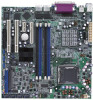
P5CR-VM specifications summary CPU Chipset Front Side Bus Memory Expansion slots Storage ...PCI Express™ 1.0a) 1 x PCI Express™ x1 slot (PCI Express™ 1.0a) 1 x Mini-PCI socket for the ASUS Server Management Board Intel® ICH6R Southbridge supports: - 2 x Ultra DMA 100/66/33 hard disk drives - 4 x Serial ATA hard ...compliant) Intel® ICH6R Southbridge supports: - 8 x USB 2.0 ports (2 on the rear panel, 6 at midboard) ASUS Smart Fan ASUS CrashFree BIOS 2 ASUS EZ Flash ASUS MyLogo2™ AMI BIOS, 8 MB FWH, Green, PnP, DMI2.0a, ACPI 2.0A, SMBIOS 2.3, Trend ChipAway Virus&#...
P5CR-VM specifications summary CPU Chipset Front Side Bus Memory Expansion slots Storage ...PCI Express™ 1.0a) 1 x PCI Express™ x1 slot (PCI Express™ 1.0a) 1 x Mini-PCI socket for the ASUS Server Management Board Intel® ICH6R Southbridge supports: - 2 x Ultra DMA 100/66/33 hard disk drives - 4 x Serial ATA hard ...compliant) Intel® ICH6R Southbridge supports: - 8 x USB 2.0 ports (2 on the rear panel, 6 at midboard) ASUS Smart Fan ASUS CrashFree BIOS 2 ASUS EZ Flash ASUS MyLogo2™ AMI BIOS, 8 MB FWH, Green, PnP, DMI2.0a, ACPI 2.0A, SMBIOS 2.3, Trend ChipAway Virus&#...

User Guide
Page 11
xi P5CR-VM specifications summary Internal connectors Power Requirement Form Factor Support CD contents 1 x Floppy disk drive connector 1x IDE connector 4 x Serial ATA connectors 2 x CPU fan connectors 4 x System fan connectors 3 x USB connectors 1 x 24-pin SSI power connector 1 x 4-pin ATX 12 V power connector 1 x Serial port connector 1 x Backplane ...-pin and 4-pin 12 V plugs) ATX 12 V 2.0 compliant uATX form factor: 9.6 in x 9.6 in (25 cm x 25 cm) Device drivers ASUS Live Update utility ASUS System Web-based Management (ASWM®) *Specifications are subject to change without notice.
xi P5CR-VM specifications summary Internal connectors Power Requirement Form Factor Support CD contents 1 x Floppy disk drive connector 1x IDE connector 4 x Serial ATA connectors 2 x CPU fan connectors 4 x System fan connectors 3 x USB connectors 1 x 24-pin SSI power connector 1 x 4-pin ATX 12 V power connector 1 x Serial port connector 1 x Backplane ...-pin and 4-pin 12 V plugs) ATX 12 V 2.0 compliant uATX form factor: 9.6 in x 9.6 in (25 cm x 25 cm) Device drivers ASUS Live Update utility ASUS System Web-based Management (ASWM®) *Specifications are subject to change without notice.

User Guide
Page 17
.... The ASIC monitors the voltage levels to a fast 480 Mbps on USB 1.1 to ensure stable supply of current for your networking needs. ASUS P5CR-VM 1-3 Temperature, fan, and voltage monitoring The CPU temperature is monitored for timely failure detection. See pages 2-20, 2-21, and 2-23 for details. This high speed interface is backward compatible...
.... The ASIC monitors the voltage levels to a fast 480 Mbps on USB 1.1 to ensure stable supply of current for your networking needs. ASUS P5CR-VM 1-3 Temperature, fan, and voltage monitoring The CPU temperature is monitored for timely failure detection. See pages 2-20, 2-21, and 2-23 for details. This high speed interface is backward compatible...
User Guide
Page 20
Chapter summary 2 2.1 Before you proceed 2-1 2.2 Motherboard overview 2-2 2.3 Central Processing Unit (CPU 2-6 2.4 System memory 2-13 2.5 Expansion slots 2-15 2.6 Jumpers 2-18 2.7 Connectors 2-23 ASUS P5CR-VM
Chapter summary 2 2.1 Before you proceed 2-1 2.2 Motherboard overview 2-2 2.3 Central Processing Unit (CPU 2-6 2.4 System memory 2-13 2.5 Expansion slots 2-15 2.6 Jumpers 2-18 2.7 Connectors 2-23 ASUS P5CR-VM

User Guide
Page 24
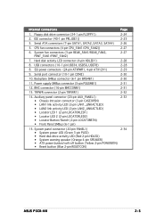
CPU fan mode selection (3-pin FM_CPU1, FM_CPU2) 3. Gigabit LAN controller setting (3-pin LAN_EN1) 6. BIOS recovery (3-pin RECOVERY1) Page 2-18 2-19 2-19 2-20 2-20 2-21 2-22 Rear ... port 2. LAN 2 (RJ-45) port Page 2-23 2-23 2-23 2-23 2-23 2-23 2-23 2-23 2-4 Chapter 2: Hardware information PCI/PCI Express slots Page 2-6 2-13 2-17 Jumpers 1. CPU socket 2. USB 2.0 ports 1 and 2 5. DDR2 DIMM sockets 3. Serial (COM1) port 6. VGA port 7. USB device wake-up (3-pin USBPW12, USBPW34, USBPW56 USBPW78) 4. Gigabit LAN controller setting...
CPU fan mode selection (3-pin FM_CPU1, FM_CPU2) 3. Gigabit LAN controller setting (3-pin LAN_EN1) 6. BIOS recovery (3-pin RECOVERY1) Page 2-18 2-19 2-19 2-20 2-20 2-21 2-22 Rear ... port 2. LAN 2 (RJ-45) port Page 2-23 2-23 2-23 2-23 2-23 2-23 2-23 2-23 2-4 Chapter 2: Hardware information PCI/PCI Express slots Page 2-6 2-13 2-17 Jumpers 1. CPU socket 2. USB 2.0 ports 1 and 2 5. DDR2 DIMM sockets 3. Serial (COM1) port 6. VGA port 7. USB device wake-up (3-pin USBPW12, USBPW34, USBPW56 USBPW78) 4. Gigabit LAN controller setting...
User Guide
Page 25
...pin PRI_IDE1)) 2-25 3. USB connectors (10-1 pin USB34, USB56, USB78) 2-28 8. Backplane SMBus connector (6-1 pin BPSMB1) 2-30 11. CPU fan connectors (4-pin CPU_FAN1/CPU_FAN2)) 2-27 6. SSI power connectors (24-pin ATXPWR1, 4-pin ATX12V1) 2-29 9. Hard disk activity LED connector (4-...speaker (Orange 4-pin SPEAKER) • ATX power button/soft-off button (Yellow 2-pin POWERBTN) • Reset button (Blue 2-pin RESETCON) 2-34 ASUS P5CR-VM 2-5 Serial port connector (10-1 pin COM2) 2-30 10. BMC connector (16-pin BMCCONN1) 2-31 13. Floppy disk drive connector (34-1 pin ...
...pin PRI_IDE1)) 2-25 3. USB connectors (10-1 pin USB34, USB56, USB78) 2-28 8. Backplane SMBus connector (6-1 pin BPSMB1) 2-30 11. CPU fan connectors (4-pin CPU_FAN1/CPU_FAN2)) 2-27 6. SSI power connectors (24-pin ATXPWR1, 4-pin ATX12V1) 2-29 9. Hard disk activity LED connector (4-...speaker (Orange 4-pin SPEAKER) • ATX power button/soft-off button (Yellow 2-pin POWERBTN) • Reset button (Blue 2-pin RESETCON) 2-34 ASUS P5CR-VM 2-5 Serial port connector (10-1 pin COM2) 2-30 10. BMC connector (16-pin BMCCONN1) 2-31 13. Floppy disk drive connector (34-1 pin ...
User Guide
Page 26
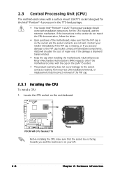
... cap/socket contacts/motherboard components. P5CR-VM P5CR-VM CPU Socket 775 Before installing the CPU, make sure that the socket box is facing towards you see any damage to the socket contacts resulting from incorrect CPU installation/removal, or misplacement/loss/incorrect removal of the PnP cap. 2.3.1 Installing the CPU To install a CPU: 1. ASUS will process Return Merchandise Authorization...
... cap/socket contacts/motherboard components. P5CR-VM P5CR-VM CPU Socket 775 Before installing the CPU, make sure that the socket box is facing towards you see any damage to the socket contacts resulting from incorrect CPU installation/removal, or misplacement/loss/incorrect removal of the PnP cap. 2.3.1 Installing the CPU To install a CPU: 1. ASUS will process Return Merchandise Authorization...
User Guide
Page 27
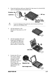
... a B 100º angle (A), then push the PnP cap from the retention tab. To prevent damage to remove (B). Position the CPU over the socket, making sure that the gold triangle is released from the load plate window to the socket pins, do not remove ... n m e n t k e y should face you are installing a CPU. 3. Lift the load lever in the direction of the arrow to the left (B) until it is on the bottom-left corner of the socket box should fit into the CPU notch. Gold triangle mark ASUS P5CR-VM A 2-7 2. Press the load lever with your thumb (A), then move...
... a B 100º angle (A), then push the PnP cap from the retention tab. To prevent damage to remove (B). Position the CPU over the socket, making sure that the gold triangle is released from the load plate window to the socket pins, do not remove ... n m e n t k e y should face you are installing a CPU. 3. Lift the load lever in the direction of the arrow to the left (B) until it is on the bottom-left corner of the socket box should fit into the CPU notch. Gold triangle mark ASUS P5CR-VM A 2-7 2. Press the load lever with your thumb (A), then move...
User Guide
Page 28
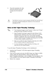
...the Hyper-Threading Techonology item in BIOS before installing a supported operating system. • For more information on the socket and damaging the CPU! Close the load plate (A), then A push the load lever (B) until it snaps into the socket to enable the Hyper-Threading Technology ...Power up the system and enter the BIOS Setup (see Chapter 4: BIOS setup). Reboot the computer. 2-8 Chapter 2: Hardware information B The CPU fits in the 775-land package with Hyper-Threading Technology. • Hyper-Threading Technology is set to compile the code. Under Linux, use ...
...the Hyper-Threading Techonology item in BIOS before installing a supported operating system. • For more information on the socket and damaging the CPU! Close the load plate (A), then A push the load lever (B) until it snaps into the socket to enable the Hyper-Threading Technology ...Power up the system and enter the BIOS Setup (see Chapter 4: BIOS setup). Reboot the computer. 2-8 Chapter 2: Hardware information B The CPU fits in the 775-land package with Hyper-Threading Technology. • Hyper-Threading Technology is set to compile the code. Under Linux, use ...

User Guide
Page 29
Place the heatsink on the motherboard. Visit the ASUS website for (www.asus.com) for emphasis.) ASUS P5CR-VM 2-9 Orient the heatsink and fan assembly such that you use ASUS-certified multi-directional heatsink and fan. To install the CPU heatsink and fan: 1. Narrow end of the groove pointing ...LGA775 heatsink and fan assembly comes in a push-pin design and requires no tool to install. • If you purchased a separate CPU heatsink and fan assembly, make sure that you have installed the motherboard to ensure optimum thermal condition and performance. • When you buy...
Place the heatsink on the motherboard. Visit the ASUS website for (www.asus.com) for emphasis.) ASUS P5CR-VM 2-9 Orient the heatsink and fan assembly such that you use ASUS-certified multi-directional heatsink and fan. To install the CPU heatsink and fan: 1. Narrow end of the groove pointing ...LGA775 heatsink and fan assembly comes in a push-pin design and requires no tool to install. • If you purchased a separate CPU heatsink and fan assembly, make sure that you have installed the motherboard to ensure optimum thermal condition and performance. • When you buy...
User Guide
Page 30
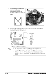
... plug this connector. • If there is only one CPU fan cable, connect it to the connectors on the motherboard labeled CPU_FAN1/CPU_FAN2. Connect the CPU fan cable to the connector labeled CPU_FAN1. CPU_FAN1 CPU_FAN1 GND FANPWR2 FANOUT4 CPU_FAN2 CPU_FAN2 FANOUT7 FANPWR3 GND P5CR-VM P5CR-VM CPU fan connectors • Do not forget to connect the...
... plug this connector. • If there is only one CPU fan cable, connect it to the connectors on the motherboard labeled CPU_FAN1/CPU_FAN2. Connect the CPU fan cable to the connector labeled CPU_FAN1. CPU_FAN1 CPU_FAN1 GND FANPWR2 FANOUT4 CPU_FAN2 CPU_FAN2 FANOUT7 FANPWR3 GND P5CR-VM P5CR-VM CPU fan connectors • Do not forget to connect the...

User Guide
Page 31
A B A B B A ASUS P5CR-VM 2-11 Rotate each fastener counterclockwise. 3. Disconnect the CPU fan cable from the A motherboard. Pull up two fasteners at a time in a diagonal sequence to disengage the heatsink B and fan assembly from the connector on the motherboard. 2. 2.3.3 Uninstalling the CPU heatsink and fan To uninstall the CPU heatsink and fan: 1.
A B A B B A ASUS P5CR-VM 2-11 Rotate each fastener counterclockwise. 3. Disconnect the CPU fan cable from the A motherboard. Pull up two fasteners at a time in a diagonal sequence to disengage the heatsink B and fan assembly from the connector on the motherboard. 2. 2.3.3 Uninstalling the CPU heatsink and fan To uninstall the CPU heatsink and fan: 1.

User Guide
Page 39
... feature requires a power supply that can provide 500mA on the +5VSB lead for each USB port; P5CR-LS P5CR-VM FM_CPU Setting FM_CPU1 21 32 DC mode PWM (Default) FM_CPU2 12 23 DC mode PWM (Default) 3 . 2 . ASUS P5CR-VM 2-19 CPU fan mode selection (3-pin FM_CPU1, FM_CPU2) These jumpers allow you to connect either a 3-pin or a 4-pin...
... feature requires a power supply that can provide 500mA on the +5VSB lead for each USB port; P5CR-LS P5CR-VM FM_CPU Setting FM_CPU1 21 32 DC mode PWM (Default) FM_CPU2 12 23 DC mode PWM (Default) 3 . 2 . ASUS P5CR-VM 2-19 CPU fan mode selection (3-pin FM_CPU1, FM_CPU2) These jumpers allow you to connect either a 3-pin or a 4-pin...

User Guide
Page 47
... CPU_FAN1 CPU_FAN2 FANOUT4 FANPWR2 GND GND FANPWR2 FANOUT4 CPU_FAN2 REAR_FAN1 REAR_FAN2 P5CR-VM FRNT_FAN1 FRNT_FAN2 REAR_FAN2 REAR_FAN1 Rotation +12V GND FRNT_FAN1 Rotation +12V GND FRNT_FAN2 P5CR-VM Fan connectors Rotation +12V GND Rotation +12V GND ASUS P5CR-VM 2-27 Connect the fan cables to the fan connectors. CPU and system fan connectors (4-pin CPU_FAN1/2, REAR_FAN1/2, FRNT_FAN1/2) The fan...
... CPU_FAN1 CPU_FAN2 FANOUT4 FANPWR2 GND GND FANPWR2 FANOUT4 CPU_FAN2 REAR_FAN1 REAR_FAN2 P5CR-VM FRNT_FAN1 FRNT_FAN2 REAR_FAN2 REAR_FAN1 Rotation +12V GND FRNT_FAN1 Rotation +12V GND FRNT_FAN2 P5CR-VM Fan connectors Rotation +12V GND Rotation +12V GND ASUS P5CR-VM 2-27 Connect the fan cables to the fan connectors. CPU and system fan connectors (4-pin CPU_FAN1/2, REAR_FAN1/2, FRNT_FAN1/2) The fan...

User Guide
Page 78
4.3.6 System Information This menu gives you an overview of the general system specifications. The BIOS automatically detects the items in this menu. AMIBIOS Version : 08.00.10 Build Date : 11/08/04 Processor Type : Genuine Intel(R) CPU 3.20 GHz Speed : 3200 MHz Count : 1 System Memory Size : 504 MB AMI BIOS Displays the auto-detected BIOS information Processor Displays the auto-detected CPU specification System Memory Displays the auto-detected system memory 4-18 Chapter 4: BIOS setup
4.3.6 System Information This menu gives you an overview of the general system specifications. The BIOS automatically detects the items in this menu. AMIBIOS Version : 08.00.10 Build Date : 11/08/04 Processor Type : Genuine Intel(R) CPU 3.20 GHz Speed : 3200 MHz Count : 1 System Memory Size : 504 MB AMI BIOS Displays the auto-detected BIOS information Processor Displays the auto-detected CPU specification System Memory Displays the auto-detected system memory 4-18 Chapter 4: BIOS setup

User Guide
Page 79
Select an item then press to enable or disable the USB function. USB Configuration MPS Configuration Remote Access Configuration CPU Configuration Chipset Onboard Devices Configuration PCI PnP Adjust system frequency/voltage 4.4.1 USB Configuration The items in this menu allow... Advanced menu The Advanced menu items allow you to change the settings for the CPU and other system devices. If no USB device is detected, the item shows N o n e. Configuration options: [Disabled] [Enabled] ASUS P5CR-VM 4-19 Take caution when changing the settings of the Advanced menu items. Incorrect field...
Select an item then press to enable or disable the USB function. USB Configuration MPS Configuration Remote Access Configuration CPU Configuration Chipset Onboard Devices Configuration PCI PnP Adjust system frequency/voltage 4.4.1 USB Configuration The items in this menu allow... Advanced menu The Advanced menu items allow you to change the settings for the CPU and other system devices. If no USB device is detected, the item shows N o n e. Configuration options: [Disabled] [Enabled] ASUS P5CR-VM 4-19 Take caution when changing the settings of the Advanced menu items. Incorrect field...

User Guide
Page 82
...[ 62] [Enabled] [Disabled] [Auto] [Auto] Hyper Threading Technology [Enabled] Sets the ratio between the CPU Core Clock and the Front Side Bus frequency. Ratio CMOS Setting [24] Sets the ratio between CPU Core Clock and the FSB Frequency. Configuration options: [ANSI] [VT100] [VT-UTF8] VT-UTF8 Combo Key... The default value of this item is set in CMOS then actual and setpoint values may not work when this menu show the CPU-related information that the BIOS automatically detects. Some operating systems may differ. Redirection after BIOS POST [Always] Sets the redirection mode ...
...[ 62] [Enabled] [Disabled] [Auto] [Auto] Hyper Threading Technology [Enabled] Sets the ratio between the CPU Core Clock and the Front Side Bus frequency. Ratio CMOS Setting [24] Sets the ratio between CPU Core Clock and the FSB Frequency. Configuration options: [ANSI] [VT100] [VT-UTF8] VT-UTF8 Combo Key... The default value of this item is set in CMOS then actual and setpoint values may not work when this menu show the CPU-related information that the BIOS automatically detects. Some operating systems may differ. Redirection after BIOS POST [Always] Sets the redirection mode ...

User Guide
Page 83
Configuration options: [Disabled] [Enabled] ASUS P5CR-VM 4-23 Refer to adjust the values. Configuration options: [Disabled] [Enabled] Max CPUID Value Limit [Disabled] Enable this item is lower when idle. Configuration options: [Disabled] [... to boot legacy operating systems that cannot support CPUs with extended CPUID functions. Microcode Updation [Enabled] Enables or disables microcode updation. In C1E mode, the CPU power consumption is auto-detected by BIOS. You can only adjust the R a t i o C M O S and the V I D C M O S setting if you to enable or disable the processor Hyper-...
Configuration options: [Disabled] [Enabled] ASUS P5CR-VM 4-23 Refer to adjust the values. Configuration options: [Disabled] [Enabled] Max CPUID Value Limit [Disabled] Enable this item is lower when idle. Configuration options: [Disabled] [... to boot legacy operating systems that cannot support CPUs with extended CPUID functions. Microcode Updation [Enabled] Enables or disables microcode updation. In C1E mode, the CPU power consumption is auto-detected by BIOS. You can only adjust the R a t i o C M O S and the V I D C M O S setting if you to enable or disable the processor Hyper-...


