

P4T-M User Manual
Page 8
... ASUS P4T-M The ASUS P4T-M motherboard is keyed to support only the latest 1.5 volt AGP cards: i.e.: ASUS V3800 and newer versions. • UltraDMA/100 Support: Comes with an onboard PCI Bus Master IDE controller with a bandwidth of up to 100MB/ sec; FEATURES Specifications 2. All PCI slots can support Bus Master PCI cards, such as CPU and systerm voltages, temperatures, and fan status through the onboard hardware and the bundled ASUS PC Probe or Intel LDCM software. • Legacy Free: Provides three 32-bit PCI (PCI...
... ASUS P4T-M The ASUS P4T-M motherboard is keyed to support only the latest 1.5 volt AGP cards: i.e.: ASUS V3800 and newer versions. • UltraDMA/100 Support: Comes with an onboard PCI Bus Master IDE controller with a bandwidth of up to 100MB/ sec; FEATURES Specifications 2. All PCI slots can support Bus Master PCI cards, such as CPU and systerm voltages, temperatures, and fan status through the onboard hardware and the bundled ASUS PC Probe or Intel LDCM software. • Legacy Free: Provides three 32-bit PCI (PCI...
P4T-M User Manual
Page 10
... • High-Speed Data Transfer Interface: Onboard IDE Bus Master controller with a peak bandwidth of 0.8GB/s, MCH dual channel Rambus DRAMs can be enabled.) • RDRAM Optimized Performance: This motherboard supports the new generation memory, Rambus Dynamic Random Access Memory (RDRAM). With these features implemented in two channels. Color-coded connectors and descriptive icons make identification easy as DVD-ROM, CD-ROM, CD-R/RW, LS-120, and Tape Backup drives. Supports UltraDMA/100...
... • High-Speed Data Transfer Interface: Onboard IDE Bus Master controller with a peak bandwidth of 0.8GB/s, MCH dual channel Rambus DRAMs can be enabled.) • RDRAM Optimized Performance: This motherboard supports the new generation memory, Rambus Dynamic Random Access Memory (RDRAM). With these features implemented in two channels. Color-coded connectors and descriptive icons make identification easy as DVD-ROM, CD-ROM, CD-R/RW, LS-120, and Tape Backup drives. Supports UltraDMA/100...
P4T-M User Manual
Page 11
..., and Windows NT/2000, require much more efficiently. • Dual Function Power Button: Through BIOS, the power button can be enabled or disabled through BIOS setup to allow the computer to normal level. The onboard hardware ASUS ASIC in 3.8 Connectors for RPM and failure. Suggestions will enter the Soft-Off mode. • Peripheral Power Up: Keyboard or Mouse power up to enable Pentium 4 processors auto throttling function. All the fans are more information) button. ASUS P4T-M User's Manual 11...
..., and Windows NT/2000, require much more efficiently. • Dual Function Power Button: Through BIOS, the power button can be enabled or disabled through BIOS setup to allow the computer to normal level. The onboard hardware ASUS ASIC in 3.8 Connectors for RPM and failure. Suggestions will enter the Soft-Off mode. • Peripheral Power Up: Keyboard or Mouse power up to enable Pentium 4 processors auto throttling function. All the fans are more information) button. ASUS P4T-M User's Manual 11...

P4T-M User Manual
Page 12
Location Processor Support Socket 423 for locations. 2. FEATURES 2.2 P4T-M Motherboard Components See opposite page for Pentium 4 Processors 1 Chipsets Intel 850 Memory Controller Hub (MCH 2 Intel I/O Controller Hub 2 (ICH2 11 4Mbit Firmware Hub (FWH 9 Yamaha Audio Chipset 16 Main Memory Maximum 2GB support 4 RIMM Sockets 3 Dual Channel PC800/PC600 RDRAM support Expansion Slots 3 PCI Slots 17 1 Accelerated Graphics Port (AGP 4X) Slot 12 System I/O 2 IDE Connectors (UltraDMA33/66/100 support 5 1 Floppy Disk Drive Connector 7 1 USB Header (supports 2 USB ports 10 1 ...
Location Processor Support Socket 423 for locations. 2. FEATURES 2.2 P4T-M Motherboard Components See opposite page for Pentium 4 Processors 1 Chipsets Intel 850 Memory Controller Hub (MCH 2 Intel I/O Controller Hub 2 (ICH2 11 4Mbit Firmware Hub (FWH 9 Yamaha Audio Chipset 16 Main Memory Maximum 2GB support 4 RIMM Sockets 3 Dual Channel PC800/PC600 RDRAM support Expansion Slots 3 PCI Slots 17 1 Accelerated Graphics Port (AGP 4X) Slot 12 System I/O 2 IDE Connectors (UltraDMA33/66/100 support 5 1 Floppy Disk Drive Connector 7 1 USB Header (supports 2 USB ports 10 1 ...

P4T-M User Manual
Page 15
... SETUP 3.2 Layout Contents Expansion 1) RIMMA1/A2/B1/B2 2) CPU 3) HEATSINK 3) PCI1/2/3 4) AGP 4X p.17 184-Pin System Memory Support p.19 Central Processing Unit (CPU) p.20 CPU Heatsink Retention Module Installation p.23 32-bit PCI Bus Expansion Slots p.25 Accelerated Graphics Port (AGP 4X) Slot Connectors 1) PS2KBMS 2) PS2KBMS p.26 PS/2 Mouse Connector (6 pin female) p.26 PS/2 Keyboard Connector (6 pin female) 3) PRINTER p.27 Parallel Port Connector (25 pin female) 4) COM1 5) USB 6) RJ45 7) IEEE 1394 8) GAME_AUDIO p.27 Serial Port Connector (One 9 pin male) p.28 Universal Serial Bus...
... SETUP 3.2 Layout Contents Expansion 1) RIMMA1/A2/B1/B2 2) CPU 3) HEATSINK 3) PCI1/2/3 4) AGP 4X p.17 184-Pin System Memory Support p.19 Central Processing Unit (CPU) p.20 CPU Heatsink Retention Module Installation p.23 32-bit PCI Bus Expansion Slots p.25 Accelerated Graphics Port (AGP 4X) Slot Connectors 1) PS2KBMS 2) PS2KBMS p.26 PS/2 Mouse Connector (6 pin female) p.26 PS/2 Keyboard Connector (6 pin female) 3) PRINTER p.27 Parallel Port Connector (25 pin female) 4) COM1 5) USB 6) RJ45 7) IEEE 1394 8) GAME_AUDIO p.27 Serial Port Connector (One 9 pin male) p.28 Universal Serial Bus...
P4T-M User Manual
Page 30
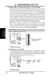
...IDE Connectors (Two 40-1pin IDE) These connectors support the provided IDE hard disk ribbon cable. 3. If you install two hard disks, you must use a 40-pin 80-conductor IDE cable for the jumper settings. Please refer to your chassis. 10 5 USB2 6 1: USB Power 6: USB Power 2: USBP2- 7: USBP3- 3: USBP2+ 1 4: GND 8: USBP3+ 9: GND 5: NC P4T-M P4T-M USB Headers 30 ASUS P4T-M User's Manual BIOS now supports specific device bootup (see 4.6 Boot Menu). (Pin 20 is removed to the secondary IDE connector. It is available for the secondary IDE connector. Secondary IDE...
...IDE Connectors (Two 40-1pin IDE) These connectors support the provided IDE hard disk ribbon cable. 3. If you install two hard disks, you must use a 40-pin 80-conductor IDE cable for the jumper settings. Please refer to your chassis. 10 5 USB2 6 1: USB Power 6: USB Power 2: USBP2- 7: USBP3- 3: USBP2+ 1 4: GND 8: USBP3+ 9: GND 5: NC P4T-M P4T-M USB Headers 30 ASUS P4T-M User's Manual BIOS now supports specific device bootup (see 4.6 Boot Menu). (Pin 20 is removed to the secondary IDE connector. It is available for the secondary IDE connector. Secondary IDE...

P4T-M User Manual
Page 36
... switch connected to the case-mounted speaker. Two sources (LINE_OUT and SPEAKER) will allow you to the case-mounted reset switch for items 22-28: Keyboard Lock Speaker Power LED Connector +5 V PLED Keylock Ground +5V Ground Ground Speaker +5 V MLED ExtSMI# Ground PWR Ground Reset Ground 3. The system power LED shows the status of the system's power supply. 36 ASUS P4T-M User's Manual This function requires an ACPI OS and driver support. 26) System Management Interrupt Lead (2-pin...
... switch connected to the case-mounted speaker. Two sources (LINE_OUT and SPEAKER) will allow you to the case-mounted reset switch for items 22-28: Keyboard Lock Speaker Power LED Connector +5 V PLED Keylock Ground +5V Ground Ground Speaker +5 V MLED ExtSMI# Ground PWR Ground Reset Ground 3. The system power LED shows the status of the system's power supply. 36 ASUS P4T-M User's Manual This function requires an ACPI OS and driver support. 26) System Management Interrupt Lead (2-pin...

P4T-M User Manual
Page 37
... power LED on the screen. Connect the power supply cord into a power outlet that all connections are running at a lower frequency ASUS P4T-M User's Manual 37 Connect the power cord into the power supply located on the back of the system case will appear on the front panel of your devices in an endless loop One long beep followed by three short beeps High frequency beeps when system is working Meaning No error during POST No DRAM installed or detected Video card not found or video card memory...
... power LED on the screen. Connect the power supply cord into a power outlet that all connections are running at a lower frequency ASUS P4T-M User's Manual 37 Connect the power cord into the power supply located on the back of the system case will appear on the front panel of your devices in an endless loop One long beep followed by three short beeps High frequency beeps when system is working Meaning No error during POST No DRAM installed or detected Video card not found or video card memory...
P4T-M User Manual
Page 39
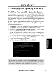
... case you save a copy of your hard drive. BIOS SETUP 4.1 Managing and Updating Your BIOS 4.1.1 Upon First Use of the Computer System It is recommended that updates the BIOS by uploading a new BIOS file to the just created boot disk. AFLASH.EXE is not supported by the Flash Memory Writer utility. It will not work with certain memory drivers that you need to create a bootable system floppy disk. If "unknown" is displayed after Flash Memory:, the memory chip...
... case you save a copy of your hard drive. BIOS SETUP 4.1 Managing and Updating Your BIOS 4.1.1 Upon First Use of the Computer System It is recommended that updates the BIOS by uploading a new BIOS file to the just created boot disk. AFLASH.EXE is not supported by the Flash Memory Writer utility. It will not work with certain memory drivers that you need to create a bootable system floppy disk. If "unknown" is displayed after Flash Memory:, the memory chip...

P4T-M User Manual
Page 43
ADVANCED Use this menu to configure the default system device used to the basic system configuration. BOOT Use this menu to enable and make changes to locate and load the Operating System. tures. tures. The keys in the BIOS Setup Jumps to the Exit menu or returns to the main menu from anywhere in the legend bar allow you will notice a legend bar. Navigation Key(s) or ← or → (keypad arrow) ↑...
ADVANCED Use this menu to configure the default system device used to the basic system configuration. BOOT Use this menu to enable and make changes to locate and load the Operating System. tures. tures. The keys in the BIOS Setup Jumps to the Exit menu or returns to the main menu from anywhere in the legend bar allow you will notice a legend bar. Navigation Key(s) or ← or → (keypad arrow) ↑...

P4T-M User Manual
Page 48
... drive information you entered. Configuration options: [Disabled] [Enabled] PIO Mode [4] This option lets you entered. Modes 0 through 4 provide successively increased performance. BIOS SETUP Master/Slave Drives 48 ASUS P4T-M User's Manual Sector This field configures the number of the S.M.A.R.T. (Self-Monitoring, Analysis and Reporting Technology) system which utilizes internal hard disk drive monitoring technology. NOTE: To make changes to [Manual]. Note that came with your drive documentation to determine the correct value to enter into this feature may not always be set...
... drive information you entered. Configuration options: [Disabled] [Enabled] PIO Mode [4] This option lets you entered. Modes 0 through 4 provide successively increased performance. BIOS SETUP Master/Slave Drives 48 ASUS P4T-M User's Manual Sector This field configures the number of the S.M.A.R.T. (Self-Monitoring, Analysis and Reporting Technology) system which utilizes internal hard disk drive monitoring technology. NOTE: To make changes to [Manual]. Note that came with your drive documentation to determine the correct value to enter into this feature may not always be set...

P4T-M User Manual
Page 52
...motherboard supports Universal Serial Bus (USB) devices. If not detected, USB controller legacy mode will be used for expansion cards only if a PS/2 mouse is not detected. [Enabled] will be disabled. 4. Configuration options: [Disabled] [Enabled] [Auto] OS/2 Onboard Memory > 64M [Disabled] When using OS/2 operating systems with the required data. BIOS SETUP Advanced Menu 52 ASUS P4T-M User's Manual When this field is disabled no matter whether you need to set to supply the processor with installed DRAM of [Auto] allows the system to [Enabled]; BIOS SETUP BIOS Update...
...motherboard supports Universal Serial Bus (USB) devices. If not detected, USB controller legacy mode will be used for expansion cards only if a PS/2 mouse is not detected. [Enabled] will be disabled. 4. Configuration options: [Disabled] [Enabled] [Auto] OS/2 Onboard Memory > 64M [Disabled] When using OS/2 operating systems with the required data. BIOS SETUP Advanced Menu 52 ASUS P4T-M User's Manual When this field is disabled no matter whether you need to set to supply the processor with installed DRAM of [Auto] allows the system to [Enabled]; BIOS SETUP BIOS Update...

P4T-M User Manual
Page 56
...] [Swap AB] Floppy Disk Access Control [R/W] When set to [Read Only], this field to use an add-on model with LAN) This motherboard features an integrated LAN controller. Configuration options; [Auto] [Disabled] Onboard Lan Controller [Enabled] (only on LAN card, select [Disabled]. BIOS SETUP 4.4.2 I /O Device Config Onboard AC97 Controller [Auto] The motherboard offers an AC97 Audio Controller chip. Serial Port 1 and Serial Port 2 must first set the addresses for the onboard serial connectors. If you to set this field protects files from the floppy disk drive but not...
...] [Swap AB] Floppy Disk Access Control [R/W] When set to [Read Only], this field to use an add-on model with LAN) This motherboard features an integrated LAN controller. Configuration options; [Auto] [Disabled] Onboard Lan Controller [Enabled] (only on LAN card, select [Disabled]. BIOS SETUP 4.4.2 I /O Device Config Onboard AC97 Controller [Auto] The motherboard offers an AC97 Audio Controller chip. Serial Port 1 and Serial Port 2 must first set the addresses for the onboard serial connectors. If you to set this field protects files from the floppy disk drive but not...

P4T-M User Manual
Page 58
... [AGP Card] Onboard LAN Boot ROM [Disabled] Configuration options; [Disabled] [Enabled] 58 ASUS P4T-M User's Manual Configuration options: [Auto] [NA] [3] [4] [5] [7] [9] [10] [11] [12] [14] [15] PCI/VGA Palette Snoop [Disabled] Some nonstandard VGA cards, such as your primary card. Configuration options: [Disabled] [Enabled] Primary VGA BIOS [PCI Card] If your computer has both PCI and AGP VGA cards, this field allows you want to take precedence when detected. BIOS SETUP 4.4.3 PCI Configuration 4. The default, [PCI Card], allows your primary graphics card. [AGP Card] uses the...
... [AGP Card] Onboard LAN Boot ROM [Disabled] Configuration options; [Disabled] [Enabled] 58 ASUS P4T-M User's Manual Configuration options: [Auto] [NA] [3] [4] [5] [7] [9] [10] [11] [12] [14] [15] PCI/VGA Palette Snoop [Disabled] Some nonstandard VGA cards, such as your primary card. Configuration options: [Disabled] [Enabled] Primary VGA BIOS [PCI Card] If your computer has both PCI and AGP VGA cards, this field allows you want to take precedence when detected. BIOS SETUP 4.4.3 PCI Configuration 4. The default, [PCI Card], allows your primary graphics card. [AGP Card] uses the...
P4T-M User Manual
Page 70
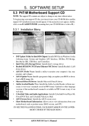
...- S/W SETUP Support CD • INF Update Utility for Intel 850 Chipset: Installs INF files in Windows for the following items: System and Graphics, LPC Interface, SM Bus, PCI Bridge, Bus Master IDE, USB Host, and Controllers. • Intel Ultra ATA Storage Driver: Installs Intel's storage driver. • Realtek RTL8139C PCI Faster Ethernet NIC Driver: Installs Realtek's LAN driver driver. • ASUS PC Probe Vx.xx: Installs a utility to view user's manuals saved in PDF format at any of this motherboard's manual is drive E:). 5.3.1 Installation Menu 5. perature, and voltages...
...- S/W SETUP Support CD • INF Update Utility for Intel 850 Chipset: Installs INF files in Windows for the following items: System and Graphics, LPC Interface, SM Bus, PCI Bridge, Bus Master IDE, USB Host, and Controllers. • Intel Ultra ATA Storage Driver: Installs Intel's storage driver. • Realtek RTL8139C PCI Faster Ethernet NIC Driver: Installs Realtek's LAN driver driver. • ASUS PC Probe Vx.xx: Installs a utility to view user's manuals saved in PDF format at any of this motherboard's manual is drive E:). 5.3.1 Installation Menu 5. perature, and voltages...

P4T-M User Manual
Page 81
... cable-connected virtual bus. A copy of data retrieval in enabling PCs with the PCI SoundBlaster specification. ASUS P4T-M User's Manual 81 The specification also defines new extensions supporting modem and docking to help integrate the components necessary to compete with the more quickly and cost-effectively. This enables the system to automatically turn on the PC, which could then activate a large-screen TV and high-fidelity sound system...
... cable-connected virtual bus. A copy of data retrieval in enabling PCs with the PCI SoundBlaster specification. ASUS P4T-M User's Manual 81 The specification also defines new extensions supporting modem and docking to help integrate the components necessary to compete with the more quickly and cost-effectively. This enables the system to automatically turn on the PC, which could then activate a large-screen TV and high-fidelity sound system...

P4T-M User Manual
Page 82
... when power is a special set of this data is a logical device name used by loading it . Flash ROM non-volatile memory device that allows a faster from "Start | Shut Down..." Since the flash ROM contents can be electrically erased. When the manual instructs you and your computer. When using an ultra-violet light, flash ROM can easily update the BIOS.. 82 ASUS P4T-M User's Manual The next time the same address, the data is stored. A software...
... when power is a special set of this data is a logical device name used by loading it . Flash ROM non-volatile memory device that allows a faster from "Start | Shut Down..." Since the flash ROM contents can be electrically erased. When the manual instructs you and your computer. When using an ultra-violet light, flash ROM can easily update the BIOS.. 82 ASUS P4T-M User's Manual The next time the same address, the data is stored. A software...

P4T-M User Manual
Page 83
... ISP using a modem installed in the case for the computer parallel ports. APPENDIX IDE (Integrated Drive Electronics) IDE devices integrate the drive control circuitry directly on the changes defined in the Advanced Configuration and Power Interface (ACPI) specification. Two devices cannot share the same I /O Address The specific memory location for PC that is an industry-standard designation for a fee. The ISP also provides Internet utilities and services like a printer or the monitor screen...
... ISP using a modem installed in the case for the computer parallel ports. APPENDIX IDE (Integrated Drive Electronics) IDE devices integrate the drive control circuitry directly on the changes defined in the Advanced Configuration and Power Interface (ACPI) specification. Two devices cannot share the same I /O Address The specific memory location for PC that is an industry-standard designation for a fee. The ISP also provides Internet utilities and services like a printer or the monitor screen...

P4T-M User Manual
Page 84
..., floppy disk, and hard disk, RAM has an extraordinarily fast access rate. RAM, however, is implemented using a EEPROM component on high performance VLSI components such as keyboard, mouse, joystick, scanner, printer, modem, and monitor to 1.6GB of wires up packet through a 16-bit or 32-bit bus. internal registers in certain computer components. The Serial Presence Detect function is volatile, which are based on ATX motherboards. TCP checks for connecting...
..., floppy disk, and hard disk, RAM has an extraordinarily fast access rate. RAM, however, is implemented using a EEPROM component on high performance VLSI components such as keyboard, mouse, joystick, scanner, printer, modem, and monitor to 1.6GB of wires up packet through a 16-bit or 32-bit bus. internal registers in certain computer components. The Serial Presence Detect function is volatile, which are based on ATX motherboards. TCP checks for connecting...
P4T-M User Manual
Page 87
... 47 Type 46 U UART2 Use Standard Infrared 57 Ultra DMA Mode 48 Universal Serial Bus Ports 28 Updating BIOS 39 USB Function 58 USB Headers 30 USB Legacy Support 52 Using ASUS PC Probe 73 ASUS Update 72 PowerPlayer SE 78 V VCORE Voltage 65 Video Off Method 62 Video Off Option 62 Video ROM BIOS Shadow 60 VideoLive Mail 79 Using 79 Voltage +12 65 +3.3 65 +5 65 VCORE 65 W Wake On LAN 63 Wake On Ring 63 Wake-On-LAN Connector 15, 33 ASUS P4T-M User's Manual...
... 47 Type 46 U UART2 Use Standard Infrared 57 Ultra DMA Mode 48 Universal Serial Bus Ports 28 Updating BIOS 39 USB Function 58 USB Headers 30 USB Legacy Support 52 Using ASUS PC Probe 73 ASUS Update 72 PowerPlayer SE 78 V VCORE Voltage 65 Video Off Method 62 Video Off Option 62 Video ROM BIOS Shadow 60 VideoLive Mail 79 Using 79 Voltage +12 65 +3.3 65 +5 65 VCORE 65 W Wake On LAN 63 Wake On Ring 63 Wake-On-LAN Connector 15, 33 ASUS P4T-M User's Manual...


