
Motherboard DIY Troubleshooting Guide
Page 1
® P4T-EM Intel® 850 ATX Motherboard USER'S MANUAL
® P4T-EM Intel® 850 ATX Motherboard USER'S MANUAL
Motherboard DIY Troubleshooting Guide
Page 4
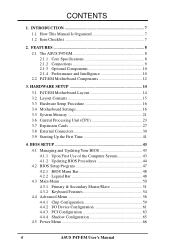
... Configuration 59 4.4.2 I/O Device Configuration 61 4.4.3 PCI Configuration 63 4.4.4 Shadow Configuration 65 4.5 Power Menu 66 4 ASUS P4T-EM User's Manual INTRODUCTION 7 1.1 How This Manual Is Organized 7 1.2 Item Checklist 7 2. HARDWARE SETUP 14 3.1 P4T-EM Motherboard Layout 14 3.2 Layout Contents 15 3.3 Hardware Setup Procedure 16 3.4 Motherboard Settings 16 3.5 System Memory 21 3.6 Central Processing Unit (CPU 23 3.7 Expansion Cards 27 3.8 External...
... Configuration 59 4.4.2 I/O Device Configuration 61 4.4.3 PCI Configuration 63 4.4.4 Shadow Configuration 65 4.5 Power Menu 66 4 ASUS P4T-EM User's Manual INTRODUCTION 7 1.1 How This Manual Is Organized 7 1.2 Item Checklist 7 2. HARDWARE SETUP 14 3.1 P4T-EM Motherboard Layout 14 3.2 Layout Contents 15 3.3 Hardware Setup Procedure 16 3.4 Motherboard Settings 16 3.5 System Memory 21 3.6 Central Processing Unit (CPU 23 3.7 Expansion Cards 27 3.8 External...

Motherboard DIY Troubleshooting Guide
Page 5
CONTENTS 4.5.1 Power Up Control 68 4.5.2 Hardware Monitor 69 4.6 Boot Menu 70 4.7 Exit Menu 72 5.1 Install Operating System 74 5.2 Start Windows 74 5. SOFTWARE SETUP 75 5.3 P4T-EM Motherboard Support CD 75 6. APPENDIX 91 7.1 Glossary 91 INDEX 95 ASUS P4T-EM User's Manual 5 SOFTWARE REFERENCE 77 6.1 Winbond Smart Manager 77 6.2 ASUS PC Probe 81 6.3 ASUS Live Update 86 6.4 CyberLink PowerPlayer SE 87 6.5 CyberLink VideoLive Mail 88 7.
CONTENTS 4.5.1 Power Up Control 68 4.5.2 Hardware Monitor 69 4.6 Boot Menu 70 4.7 Exit Menu 72 5.1 Install Operating System 74 5.2 Start Windows 74 5. SOFTWARE SETUP 75 5.3 P4T-EM Motherboard Support CD 75 6. APPENDIX 91 7.1 Glossary 91 INDEX 95 ASUS P4T-EM User's Manual 5 SOFTWARE REFERENCE 77 6.1 Winbond Smart Manager 77 6.2 ASUS PC Probe 81 6.3 ASUS Live Update 86 6.4 CyberLink PowerPlayer SE 87 6.5 CyberLink VideoLive Mail 88 7.
Motherboard DIY Troubleshooting Guide
Page 7
... on setting up the BIOS Intructions on motherboard) (2) ASUS C-RIMM Continuity RIMM Optional Items ASUS IrDA-compliant infrared module Two Rambus Memory Modules LAN Card: PCI-L3C920 1394 Card: PCI-1394E ASUS P4T-EM User's Manual 7 Package Contents (1) ASUS Motherboard (1) 40-pin 80-conductor ribbon cable ... the included software Reference material for (1) 5.25" and (2) 3.5" floppy disk drives (1) ASUS 2-port USB connector set with bracket (1) Bag of spare jumpers (1) Support drivers and utilities (1) This Motherboard User's Manual (1) CPU Retention Module (Preinstalled on setting up the...
... on setting up the BIOS Intructions on motherboard) (2) ASUS C-RIMM Continuity RIMM Optional Items ASUS IrDA-compliant infrared module Two Rambus Memory Modules LAN Card: PCI-L3C920 1394 Card: PCI-1394E ASUS P4T-EM User's Manual 7 Package Contents (1) ASUS Motherboard (1) 40-pin 80-conductor ribbon cable ... the included software Reference material for (1) 5.25" and (2) 3.5" floppy disk drives (1) ASUS 2-port USB connector set with bracket (1) Bag of spare jumpers (1) Support drivers and utilities (1) This Motherboard User's Manual (1) CPU Retention Module (Preinstalled on setting up the...

Motherboard DIY Troubleshooting Guide
Page 8
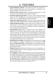
...I /O Controller and Firmware Hub) with support for UltraDMA/100, which allows burst mode data transfer rates of the processor's external frequency. 8 ASUS P4T-EM User's Manual These RDRAMs are included to allow manual adjustment of up to 100MB/ sec; Supports UltraDMA/100, UltraDMA/66, UltraDMA/33, PIO... are necessary to meet the increase in 64, 96, 128, 192, 256, 512MB) up to 2GB. 2. FEATURES 2.1 The ASUS P4T-EM The ASUS P4T-EM motherboard is required. • Intel® Accelerated Hub Architecture: Features a dedicated high speed hub link between the ICH2 and MCH with two...
...I /O Controller and Firmware Hub) with support for UltraDMA/100, which allows burst mode data transfer rates of the processor's external frequency. 8 ASUS P4T-EM User's Manual These RDRAMs are included to allow manual adjustment of up to 100MB/ sec; Supports UltraDMA/100, UltraDMA/66, UltraDMA/33, PIO... are necessary to meet the increase in 64, 96, 128, 192, 256, 512MB) up to 2GB. 2. FEATURES 2.1 The ASUS P4T-EM The ASUS P4T-EM motherboard is required. • Intel® Accelerated Hub Architecture: Features a dedicated high speed hub link between the ICH2 and MCH with two...

Motherboard DIY Troubleshooting Guide
Page 10
...a new technology to enable Pentium 4 processors auto throttling function. This function ensures the best performance and reliability. 10 ASUS P4T-EM User's Manual 2. ACPI provides more control and protection for future operating systems (OS) supporting OS Direct Power Management ..., up to wait for a long time for full networking capability. 2.1.4 Performance and Intelligence • RDRAM Optimized Performance: This motherboard supports Rambus Dynamic Random Access Memory (RDRAM). FEATURES Options / Performance 2. Supports Vcore and CPU/RDRAM frequency adjustments, boot block ...
...a new technology to enable Pentium 4 processors auto throttling function. This function ensures the best performance and reliability. 10 ASUS P4T-EM User's Manual 2. ACPI provides more control and protection for future operating systems (OS) supporting OS Direct Power Management ..., up to wait for a long time for full networking capability. 2.1.4 Performance and Intelligence • RDRAM Optimized Performance: This motherboard supports Rambus Dynamic Random Access Memory (RDRAM). FEATURES Options / Performance 2. Supports Vcore and CPU/RDRAM frequency adjustments, boot block ...
Motherboard DIY Troubleshooting Guide
Page 11
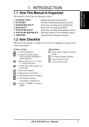
... Switch Lead in conjunction with either the bundled ASUS PC Probe or Intel LDCM will enter the Soft-Off mode. • Peripheral Power Up: Keyboard or Mouse power up to critical motherboard components. Regardless of the motherboard meet the stringent requirements for more memory and... hard drive space to be enabled or disabled through BIOS setup to allow the computer to present enormous user interfaces and run large applications. ASUS P4T-EM User's Manual 11...
... Switch Lead in conjunction with either the bundled ASUS PC Probe or Intel LDCM will enter the Soft-Off mode. • Peripheral Power Up: Keyboard or Mouse power up to critical motherboard components. Regardless of the motherboard meet the stringent requirements for more memory and... hard drive space to be enabled or disabled through BIOS setup to allow the computer to present enormous user interfaces and run large applications. ASUS P4T-EM User's Manual 11...

Motherboard DIY Troubleshooting Guide
Page 12
2. FEATURES 2.2 P4T-EM Motherboard Components See opposite page for Pentium 4 Processors 3 Chipsets Intel 850 Memory Controller Hub (MCH 5 Intel I/O Controller Hub 2 (ICH2 11 2Mbit Firmware Hub (FWH 13 ... Connector Bottom) 22 1 Line In Connector Bottom) 22 1 Line Microphone Connector Bottom) 22 Hardware Monitoring ASUS onboard chipset 10 Power ATX Power Supply Connector 2 ATX 12V Power Supply Connector 4 Special Feature Onboard LED 14 Form Factor MicroATX 12 ASUS P4T-EM User's Manual Location Processor Support Socket 478 for locations. FEATURES MB Components 2.
2. FEATURES 2.2 P4T-EM Motherboard Components See opposite page for Pentium 4 Processors 3 Chipsets Intel 850 Memory Controller Hub (MCH 5 Intel I/O Controller Hub 2 (ICH2 11 2Mbit Firmware Hub (FWH 13 ... Connector Bottom) 22 1 Line In Connector Bottom) 22 1 Line Microphone Connector Bottom) 22 Hardware Monitoring ASUS onboard chipset 10 Power ATX Power Supply Connector 2 ATX 12V Power Supply Connector 4 Special Feature Onboard LED 14 Form Factor MicroATX 12 ASUS P4T-EM User's Manual Location Processor Support Socket 478 for locations. FEATURES MB Components 2.

Motherboard DIY Troubleshooting Guide
Page 14
HARDWARE SETUP 3.1 P4T-EM Motherboard Layout PS/2KBMS T: Mouse B: Keyboard Bottom: Top: USB1 RJ-... 850 Memory Controller Hub (MCH) GAME_AUDIO Line In Mic In AUX MODEM CD1 J11 J12 INTEL_FPANEL1 Audio Codec P4T-EM ATX12V CPU_FAN Accelerated Graphics Port (AGP) PCI1 OC3 J3J3+ Intel I/O HDDLED Controller Hub (ICH2) CLCMOS ADN...CR2032 3V Lithium Cell CMOS Power PANEL 2Mbit Firmware Hub FLOPPY ASUS ASIC USB2 Grayed components are available only on certain models at the time of purchase. 14 ASUS P4T-EM User's Manual H/W SETUP Motherboard Layout PRIMARY IDE 24.4cm (9.6in) 3. 3.
HARDWARE SETUP 3.1 P4T-EM Motherboard Layout PS/2KBMS T: Mouse B: Keyboard Bottom: Top: USB1 RJ-... 850 Memory Controller Hub (MCH) GAME_AUDIO Line In Mic In AUX MODEM CD1 J11 J12 INTEL_FPANEL1 Audio Codec P4T-EM ATX12V CPU_FAN Accelerated Graphics Port (AGP) PCI1 OC3 J3J3+ Intel I/O HDDLED Controller Hub (ICH2) CLCMOS ADN...CR2032 3V Lithium Cell CMOS Power PANEL 2Mbit Firmware Hub FLOPPY ASUS ASIC USB2 Grayed components are available only on certain models at the time of purchase. 14 ASUS P4T-EM User's Manual H/W SETUP Motherboard Layout PRIMARY IDE 24.4cm (9.6in) 3. 3.
Motherboard DIY Troubleshooting Guide
Page 15
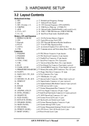
H/W SETUP Layout Contents 3. 3. HARDWARE SETUP 3.2 Layout Contents Motherboard Settings 1) SW1 p. 17 Motherboard Frequency Settings 2) LED p. 17 Onboard Power Signal 3) SW1 (Switches 1-5) p. 18 CPU External Frequency ...Supply Connector (20 pin) (4 pin) 19) INTEL_FPANEL1 p.39 Intel Front Panel Audio Connector (10-1 pin) (optional) 20) SMARTCON p.39 ASUS SmartCard Connector (14-1 pin ) 21) PLED (PANEL) p.40 System Power LED Lead (3-1 pin) 22) KEYLOCK (PANEL) p.40 Keyboard ...Off Switch Lead (2 pin) 27) RESET (PANEL) p.40 Reset Switch Lead (2 pin) ASUS P4T-EM User's Manual 15
H/W SETUP Layout Contents 3. 3. HARDWARE SETUP 3.2 Layout Contents Motherboard Settings 1) SW1 p. 17 Motherboard Frequency Settings 2) LED p. 17 Onboard Power Signal 3) SW1 (Switches 1-5) p. 18 CPU External Frequency ...Supply Connector (20 pin) (4 pin) 19) INTEL_FPANEL1 p.39 Intel Front Panel Audio Connector (10-1 pin) (optional) 20) SMARTCON p.39 ASUS SmartCard Connector (14-1 pin ) 21) PLED (PANEL) p.40 System Power LED Lead (3-1 pin) 22) KEYLOCK (PANEL) p.40 Keyboard ...Off Switch Lead (2 pin) 27) RESET (PANEL) p.40 Reset Switch Lead (2 pin) ASUS P4T-EM User's Manual 15

Motherboard DIY Troubleshooting Guide
Page 16
... to a metal object, such as the power supply case. 3. Ensure that the ATX power supply is recommended for this motherboard. Complete the following steps before handling computer components. H/W SETUP Getting Started 16 ASUS P4T-EM User's Manual 3. For heavily-loaded configurations, an ATX12V power supply of your computer. 1. To protect them against damage from...
... to a metal object, such as the power supply case. 3. Ensure that the ATX power supply is recommended for this motherboard. Complete the following steps before handling computer components. H/W SETUP Getting Started 16 ASUS P4T-EM User's Manual 3. For heavily-loaded configurations, an ATX12V power supply of your computer. 1. To protect them against damage from...

Motherboard DIY Troubleshooting Guide
Page 17
... if power is connected and operating okay and when the system is in the OFF position. P4T-EM ® P4T-EM Onboard LED ON Standby Power OFF Powered Off ASUS P4T-EM User's Manual 17 HARDWARE SETUP 1) Motherboard Frequency Settings (SW1) The motherboard frequency is lit, since the user risks electrical shock and/or disabling system configuration. The illustration...
... if power is connected and operating okay and when the system is in the OFF position. P4T-EM ® P4T-EM Onboard LED ON Standby Power OFF Powered Off ASUS P4T-EM User's Manual 17 HARDWARE SETUP 1) Motherboard Frequency Settings (SW1) The motherboard frequency is lit, since the user risks electrical shock and/or disabling system configuration. The illustration...

Motherboard DIY Troubleshooting Guide
Page 18
... option tells the clock generator what frequency to send to be stable. This allows the selection of the CPU's External frequency (or BUS Clock). P4T-EM SW1 Default Setting CPU 100.0MHz AGP 66.0MHz PCI 33.0MHz ON 12345 ON 12345 103.0MHz 68.0MHz 34.0MHz ON 12345 ON...[OFF] [OFF] [ON] [ON] [ON] 105 70 35 [ON] [ON] [OFF] [ON] [ON] 110 73 36 [ON] [OFF] [OFF] [ON] [ON] WARNING! H/W SETUP Motherboard Settings 18 ASUS P4T-EM User's Manual 3. Set the CPU frequency only to the recommended settings. The BUS Clock multiplied by the Frequency Multiple equals the CPU's Internal frequency...
... option tells the clock generator what frequency to send to be stable. This allows the selection of the CPU's External frequency (or BUS Clock). P4T-EM SW1 Default Setting CPU 100.0MHz AGP 66.0MHz PCI 33.0MHz ON 12345 ON 12345 103.0MHz 68.0MHz 34.0MHz ON 12345 ON...[OFF] [OFF] [ON] [ON] [ON] 105 70 35 [ON] [ON] [OFF] [ON] [ON] 110 73 36 [ON] [OFF] [OFF] [ON] [ON] WARNING! H/W SETUP Motherboard Settings 18 ASUS P4T-EM User's Manual 3. Set the CPU frequency only to the recommended settings. The BUS Clock multiplied by the Frequency Multiple equals the CPU's Internal frequency...

Motherboard DIY Troubleshooting Guide
Page 19
... H/W SETUP Motherboard Settings 3. HARDWARE SETUP 4) USB Device Wake-up (USBPWR) The jumpers are set to +5V as the default to support the other mode). system running in this section). RAM in reduced power mode). Otherwise, the system does not power up from the S1 sleep state (CPU stopped; P4T-EM USBPWR 2... 2-3 to select +5V (because not all computers have the appropriate power supply to allow wake up . 2. Setting Enable Disable ADN [1-2] (default) [2-3] P4T-EM ® P4T-EM AUDIO Setting ADN 3 2 2 1 ENABLE AUDIO (Default) DISABLE AUDIO ASUS P4T-EM User's Manual 19 3.
... H/W SETUP Motherboard Settings 3. HARDWARE SETUP 4) USB Device Wake-up (USBPWR) The jumpers are set to +5V as the default to support the other mode). system running in this section). RAM in reduced power mode). Otherwise, the system does not power up from the S1 sleep state (CPU stopped; P4T-EM USBPWR 2... 2-3 to select +5V (because not all computers have the appropriate power supply to allow wake up . 2. Setting Enable Disable ADN [1-2] (default) [2-3] P4T-EM ® P4T-EM AUDIO Setting ADN 3 2 2 1 ENABLE AUDIO (Default) DISABLE AUDIO ASUS P4T-EM User's Manual 19 3.

Motherboard DIY Troubleshooting Guide
Page 20
... connectors, ie.: Line_out. H/W SETUP Motherboard Settings P4T-EM ® P4T-EM CNR/USB Selection 2 1 USB2 (Default) 3 2 CNRUSB 7) Intel Front Panel Audio Selection (J11, J12) The motherboard ships with two jumper caps on default completes the circuit for the INTEL_FPANEL1 connector.) J11 J12 P4T-EM ® P4T-EM Internal Line Out Connectors LAP_LT LAP_LTT LAP_RT LAP_RTT 20 ASUS P4T-EM User's Manual HARDWARE SETUP...
... connectors, ie.: Line_out. H/W SETUP Motherboard Settings P4T-EM ® P4T-EM CNR/USB Selection 2 1 USB2 (Default) 3 2 CNRUSB 7) Intel Front Panel Audio Selection (J11, J12) The motherboard ships with two jumper caps on default completes the circuit for the INTEL_FPANEL1 connector.) J11 J12 P4T-EM ® P4T-EM Internal Line Out Connectors LAP_LT LAP_LTT LAP_RT LAP_RTT 20 ASUS P4T-EM User's Manual HARDWARE SETUP...
Motherboard DIY Troubleshooting Guide
Page 21
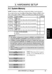
... 128MB RDRAM RIMMB2 C-RIMM RIMMB1 128MB RDRAM C-RIMM RIMMA2 RIMMA1 c. 128MB RDRAM RIMMB2 128MB RDRAM RIMMB1 128MB RDRAM 128MB RDRAM RIMMA2 RIMMA1 ASUS P4T-EM User's Manual 21 C-RIMMs (Continuity RIMM) must be populated) RIMMB2 (Rows 6&7) RDRAM x 1 C-RIMM (use configuration a. C-RIMM... which are not populated by RDRAMs. A C-RIMM is recommended that you use when socket will not be identical (see below). 2. This motherboard has four 184-pin Rambus Inline Memory Modules (RIMM) sockets. 3. The memory configuration of a Rambus interface. 3. a. H/W SETUP System...
... 128MB RDRAM RIMMB2 C-RIMM RIMMB1 128MB RDRAM C-RIMM RIMMA2 RIMMA1 c. 128MB RDRAM RIMMB2 128MB RDRAM RIMMB1 128MB RDRAM 128MB RDRAM RIMMA2 RIMMA1 ASUS P4T-EM User's Manual 21 C-RIMMs (Continuity RIMM) must be populated) RIMMB2 (Rows 6&7) RDRAM x 1 C-RIMM (use configuration a. C-RIMM... which are not populated by RDRAMs. A C-RIMM is recommended that you use when socket will not be identical (see below). 2. This motherboard has four 184-pin Rambus Inline Memory Modules (RIMM) sockets. 3. The memory configuration of a Rambus interface. 3. a. H/W SETUP System...

Motherboard DIY Troubleshooting Guide
Page 23
... on the system. Gold Arrow 3. Gold Arrow 90 - 100 CAUTION! The CPU fits in one orientation and should be possible. ASUS P4T-EM User's Manual 23 HARDWARE SETUP 3.6 Central Processing Unit (CPU) The motherboard provides a ZIF Socket 478, for bent pins. 3. Install an Intel fan heatsink. NOTE: Do not forget to prevent overheating. The...
... on the system. Gold Arrow 3. Gold Arrow 90 - 100 CAUTION! The CPU fits in one orientation and should be possible. ASUS P4T-EM User's Manual 23 HARDWARE SETUP 3.6 Central Processing Unit (CPU) The motherboard provides a ZIF Socket 478, for bent pins. 3. Install an Intel fan heatsink. NOTE: Do not forget to prevent overheating. The...

Motherboard DIY Troubleshooting Guide
Page 24
... damage both the processor and the motherboard. H/W SETUP CPU Heatsink WARNING! If a CPU is already installed on the retention module base. NOTE: If using a rectangular heatsink, use an Intel certified heatsink and fan. 3. Step 1: Mount the Heatsink Place the heatsink on the shorter side. 24 ASUS P4T-EM User's Manual Note that project and...
... damage both the processor and the motherboard. H/W SETUP CPU Heatsink WARNING! If a CPU is already installed on the retention module base. NOTE: If using a rectangular heatsink, use an Intel certified heatsink and fan. 3. Step 1: Mount the Heatsink Place the heatsink on the shorter side. 24 ASUS P4T-EM User's Manual Note that project and...

Motherboard DIY Troubleshooting Guide
Page 26
... the fan, heatsink, and the retention mechanism in place, attach the CPU fan cable to keep the CPU in place. CPU Fan Connector (CPUFAN) 26 ASUS P4T-EM User's Manual The heatsink should point to opposite directions. 3. With the added weight of the CPU fan and heatsink locking brace, no extra force is... the fan connector. 3. Connect the CPU fan cable to the module base. HARDWARE SETUP Step 3: Lock the Retention Mechanism Push down the locks on the motherboard labelled CPUFAN. When secure, the retention locks should entirely cover the CPU.
... the fan, heatsink, and the retention mechanism in place, attach the CPU fan cable to keep the CPU in place. CPU Fan Connector (CPUFAN) 26 ASUS P4T-EM User's Manual The heatsink should point to opposite directions. 3. With the added weight of the CPU fan and heatsink locking brace, no extra force is... the fan connector. 3. Connect the CPU fan cable to the module base. HARDWARE SETUP Step 3: Lock the Retention Mechanism Push down the locks on the motherboard labelled CPUFAN. When secure, the retention locks should entirely cover the CPU.
Motherboard DIY Troubleshooting Guide
Page 27
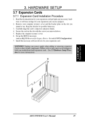
... information). 3. Remove your computer system's cover and the bracket plate on the slot with the screw you intend to both your motherboard and expansion cards. (See 3.3 Hardware Setup Procedure for your expansion card. HARDWARE SETUP 3.7 Expansion Cards 3.7.1 Expansion Card Installation Procedure...to do so may cause severe damage to use . 3. Carefully align the card's connectors and press firmly. 4. H/W SETUP Expansion Cards ASUS P4T-EM User's Manual 27 3. Keep the bracket for possible future use . Read the documentation for your power supply when adding or removing expansion ...
... information). 3. Remove your computer system's cover and the bracket plate on the slot with the screw you intend to both your motherboard and expansion cards. (See 3.3 Hardware Setup Procedure for your expansion card. HARDWARE SETUP 3.7 Expansion Cards 3.7.1 Expansion Card Installation Procedure...to do so may cause severe damage to use . 3. Carefully align the card's connectors and press firmly. 4. H/W SETUP Expansion Cards ASUS P4T-EM User's Manual 27 3. Keep the bracket for possible future use . Read the documentation for your power supply when adding or removing expansion ...


