Motherboard DIY Troubleshooting Guide
Page 4
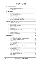
FEATURES 8 2.1 The ASUS P4T-EM 8 2.1.1 Core Specifications 8 2.1.2 Connections 9 2.1.3 Optional Components 10 2.1.4 Performance and Intelligence 10 2.2 P4T-EM Motherboard Components 12 3. BIOS SETUP 43 4.1 Managing and Updating Your BIOS 43 ... Configuration 65 4.5 Power Menu 66 4 ASUS P4T-EM User's Manual INTRODUCTION 7 1.1 How This Manual Is Organized 7 1.2 Item Checklist 7 2. HARDWARE SETUP 14 3.1 P4T-EM Motherboard Layout 14 3.2 Layout Contents 15 3.3 Hardware Setup Procedure 16 3.4 Motherboard Settings 16 3.5 System Memory 21 3.6 Central Processing Unit (CPU 23...
FEATURES 8 2.1 The ASUS P4T-EM 8 2.1.1 Core Specifications 8 2.1.2 Connections 9 2.1.3 Optional Components 10 2.1.4 Performance and Intelligence 10 2.2 P4T-EM Motherboard Components 12 3. BIOS SETUP 43 4.1 Managing and Updating Your BIOS 43 ... Configuration 65 4.5 Power Menu 66 4 ASUS P4T-EM User's Manual INTRODUCTION 7 1.1 How This Manual Is Organized 7 1.2 Item Checklist 7 2. HARDWARE SETUP 14 3.1 P4T-EM Motherboard Layout 14 3.2 Layout Contents 15 3.3 Hardware Setup Procedure 16 3.4 Motherboard Settings 16 3.5 System Memory 21 3.6 Central Processing Unit (CPU 23...
Motherboard DIY Troubleshooting Guide
Page 7
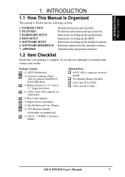
... information and specifications Intructions on setting up the included software Reference material for (1) 5.25" and (2) 3.5" floppy disk drives (1) ASUS 2-port USB connector set with bracket (1) Bag of spare jumpers (1) Support drivers and utilities (1) This Motherboard User's Manual (1)... SETUP 4. INTRODUCTION Manual / Checklist 1. Intructions on setting up the BIOS Intructions on motherboard) (2) ASUS C-RIMM Continuity RIMM Optional Items ASUS IrDA-compliant infrared module Two Rambus Memory Modules LAN Card: PCI-L3C920 1394 Card: PCI-1394E ASUS P4T-EM User's Manual 7
... information and specifications Intructions on setting up the included software Reference material for (1) 5.25" and (2) 3.5" floppy disk drives (1) ASUS 2-port USB connector set with bracket (1) Bag of spare jumpers (1) Support drivers and utilities (1) This Motherboard User's Manual (1)... SETUP 4. INTRODUCTION Manual / Checklist 1. Intructions on setting up the BIOS Intructions on motherboard) (2) ASUS C-RIMM Continuity RIMM Optional Items ASUS IrDA-compliant infrared module Two Rambus Memory Modules LAN Card: PCI-L3C920 1394 Card: PCI-1394E ASUS P4T-EM User's Manual 7

Motherboard DIY Troubleshooting Guide
Page 8
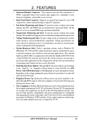
... Features the Intel® 850 chipset (82850 Memory Controller Hub, I /O: Provides two high-speed UART ompatible serial ports and one parallel port with two connectors that support four IDE devices on two channels. FEATURES 2.1 The ASUS P4T-EM The ASUS P4T-EM motherboard is carefully designed for UltraDMA/100, which ... between the ICH2 and MCH with a bandwidth of up to 2GB. twice the maximum bandwidth of the processor's external frequency. 8 ASUS P4T-EM User's Manual UART2 can also be directed from COM2 to the Infrared Module for AGP 4X Mode, (1.5 volt only); 400MHz Front Side ...
... Features the Intel® 850 chipset (82850 Memory Controller Hub, I /O: Provides two high-speed UART ompatible serial ports and one parallel port with two connectors that support four IDE devices on two channels. FEATURES 2.1 The ASUS P4T-EM The ASUS P4T-EM motherboard is carefully designed for UltraDMA/100, which ... between the ICH2 and MCH with a bandwidth of up to 2GB. twice the maximum bandwidth of the processor's external frequency. 8 ASUS P4T-EM User's Manual UART2 can also be directed from COM2 to the Infrared Module for AGP 4X Mode, (1.5 volt only); 400MHz Front Side ...

Motherboard DIY Troubleshooting Guide
Page 9
..., component level interconnect targeted at 3D graphical applications using a 4X mode bus. Supplies the MB with no ISA, eliminating bottlenecks and system memory management issues. FEATURES Connections 2. FEATURES 2.1.2 Connections • CPU socket: 478-pin surface mount, ZIF socket mPGA478 B. • PCI Expansion... PCI, which allows multiple PCI transfers from PCI master bus to four Ultra DMA/100/66, PIO Modes 3 & 4 IDE devices. ASUS P4T-EM User's Manual 9 One side of the connector is slotted to prevent incorrect insertion of major PC functions. • USB ports: Four ...
..., component level interconnect targeted at 3D graphical applications using a 4X mode bus. Supplies the MB with no ISA, eliminating bottlenecks and system memory management issues. FEATURES Connections 2. FEATURES 2.1.2 Connections • CPU socket: 478-pin surface mount, ZIF socket mPGA478 B. • PCI Expansion... PCI, which allows multiple PCI transfers from PCI master bus to four Ultra DMA/100/66, PIO Modes 3 & 4 IDE devices. ASUS P4T-EM User's Manual 9 One side of the connector is slotted to prevent incorrect insertion of major PC functions. • USB ports: Four ...

Motherboard DIY Troubleshooting Guide
Page 10
...when temperature lowers to enable Pentium 4 processors auto throttling function. This function ensures the best performance and reliability. 10 ASUS P4T-EM User's Manual 2. FEATURES 2.1.3 Optional Components • AC'97 Codec: The latest high-performance mini-chipset supports hi-... for full networking capability. 2.1.4 Performance and Intelligence • RDRAM Optimized Performance: This motherboard supports Rambus Dynamic Random Access Memory (RDRAM). ACPI provides more control and protection for virtually automatic setup. When auto throttling is a new technology to normal...
...when temperature lowers to enable Pentium 4 processors auto throttling function. This function ensures the best performance and reliability. 10 ASUS P4T-EM User's Manual 2. FEATURES 2.1.3 Optional Components • AC'97 Codec: The latest high-performance mini-chipset supports hi-... for full networking capability. 2.1.4 Performance and Intelligence • RDRAM Optimized Performance: This motherboard supports Rambus Dynamic Random Access Memory (RDRAM). ACPI provides more control and protection for virtually automatic setup. When auto throttling is a new technology to normal...
Motherboard DIY Troubleshooting Guide
Page 11
...Stand by" (ie.: Suspend or Sleep) button or as required by PC 99. The onboard hardware ASUS ASIC in 3.8 Connectors for future processors, so monitoring is necessary to ensure proper system configuration and management.... system damage, the CPU and MAIN fans are based on managing their limited resources more memory and hard drive space to be enabled or disabled through BIOS setup to allow the computer...Off (see ATX Power / Soft-Off Switch Lead in conjunction with either the bundled ASUS PC Probe or Intel LDCM will enter the Soft-Off mode. • Peripheral Power Up:...
...Stand by" (ie.: Suspend or Sleep) button or as required by PC 99. The onboard hardware ASUS ASIC in 3.8 Connectors for future processors, so monitoring is necessary to ensure proper system configuration and management.... system damage, the CPU and MAIN fans are based on managing their limited resources more memory and hard drive space to be enabled or disabled through BIOS setup to allow the computer...Off (see ATX Power / Soft-Off Switch Lead in conjunction with either the bundled ASUS PC Probe or Intel LDCM will enter the Soft-Off mode. • Peripheral Power Up:...

Motherboard DIY Troubleshooting Guide
Page 12
... locations. 2. FEATURES 2.2 P4T-EM Motherboard Components See opposite page for Pentium 4 Processors 3 Chipsets Intel 850 Memory Controller Hub (MCH 5 Intel I/O Controller Hub 2 (ICH2 11 2Mbit Firmware Hub (FWH 13 Low Pin Count (LPC) Super Multi-I/O Chipset 17 Main Memory Maximum 2GB support RIMM Sockets...Line Out Connector Bottom) 22 1 Line In Connector Bottom) 22 1 Line Microphone Connector Bottom) 22 Hardware Monitoring ASUS onboard chipset 10 Power ATX Power Supply Connector 2 ATX 12V Power Supply Connector 4 Special Feature Onboard LED 14 Form Factor MicroATX ...
... locations. 2. FEATURES 2.2 P4T-EM Motherboard Components See opposite page for Pentium 4 Processors 3 Chipsets Intel 850 Memory Controller Hub (MCH 5 Intel I/O Controller Hub 2 (ICH2 11 2Mbit Firmware Hub (FWH 13 Low Pin Count (LPC) Super Multi-I/O Chipset 17 Main Memory Maximum 2GB support RIMM Sockets...Line Out Connector Bottom) 22 1 Line In Connector Bottom) 22 1 Line Microphone Connector Bottom) 22 Hardware Monitoring ASUS onboard chipset 10 Power ATX Power Supply Connector 2 ATX 12V Power Supply Connector 4 Special Feature Onboard LED 14 Form Factor MicroATX ...

Motherboard DIY Troubleshooting Guide
Page 14
...16/18 bit, 184-pin module) PARALLEL PORT Socket 478 COM2 Line Out Intel 850 Memory Controller Hub (MCH) GAME_AUDIO Line In Mic In AUX MODEM CD1 J11 J12 INTEL_FPANEL1 Audio Codec P4T-EM ATX12V CPU_FAN Accelerated Graphics Port (AGP) PCI1 OC3 J3J3+ Intel I/O HDDLED Controller Hub ...(ICH2) CLCMOS ADN SPDIFOUT Super I/O PCI2 SMB CNR_SLOT ® LED1 IR SMARTCON CHASSIS CR2032 3V Lithium Cell CMOS Power PANEL 2Mbit Firmware Hub FLOPPY ASUS ASIC USB2 ...
...16/18 bit, 184-pin module) PARALLEL PORT Socket 478 COM2 Line Out Intel 850 Memory Controller Hub (MCH) GAME_AUDIO Line In Mic In AUX MODEM CD1 J11 J12 INTEL_FPANEL1 Audio Codec P4T-EM ATX12V CPU_FAN Accelerated Graphics Port (AGP) PCI1 OC3 J3J3+ Intel I/O HDDLED Controller Hub ...(ICH2) CLCMOS ADN SPDIFOUT Super I/O PCI2 SMB CNR_SLOT ® LED1 IR SMARTCON CHASSIS CR2032 3V Lithium Cell CMOS Power PANEL 2Mbit Firmware Hub FLOPPY ASUS ASIC USB2 ...
Motherboard DIY Troubleshooting Guide
Page 15
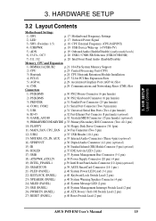
... (USB2/CNRUSB) 7) J11, J12 p. 20 Intel Front Panel Audio (Enable/Disable) Memory, CPU and Expansion 1) RIMMA1/A2/B1/B2 p.21 184-Pin System Memory Support 2) CPU p.23 Central Processing Unit (CPU) 3) Heatsink p.24 CPU Heatsink Retention...(20 pin) (4 pin) 19) INTEL_FPANEL1 p.39 Intel Front Panel Audio Connector (10-1 pin) (optional) 20) SMARTCON p.39 ASUS SmartCard Connector (14-1 pin ) 21) PLED (PANEL) p.40 System Power LED Lead (3-1 pin) 22) KEYLOCK (PANEL) p.40... pin) 27) RESET (PANEL) p.40 Reset Switch Lead (2 pin) ASUS P4T-EM User's Manual 15 H/W SETUP Layout Contents 3.
... (USB2/CNRUSB) 7) J11, J12 p. 20 Intel Front Panel Audio (Enable/Disable) Memory, CPU and Expansion 1) RIMMA1/A2/B1/B2 p.21 184-Pin System Memory Support 2) CPU p.23 Central Processing Unit (CPU) 3) Heatsink p.24 CPU Heatsink Retention...(20 pin) (4 pin) 19) INTEL_FPANEL1 p.39 Intel Front Panel Audio Connector (10-1 pin) (optional) 20) SMARTCON p.39 ASUS SmartCard Connector (14-1 pin ) 21) PLED (PANEL) p.40 System Power LED Lead (3-1 pin) 22) KEYLOCK (PANEL) p.40... pin) 27) RESET (PANEL) p.40 Reset Switch Lead (2 pin) ASUS P4T-EM User's Manual 15 H/W SETUP Layout Contents 3.

Motherboard DIY Troubleshooting Guide
Page 16
...can supply at least 230W and at least 8.5A on the motherboard. 3. Complete the following steps before using your computer. 1. Install memory modules 3. Configure the BIOS parameter settings 3.4 Motherboard Settings This section tells you do not have one, touch both of 300W may be...is switched off before handling computer components. Check motherboard settings 2. Install the Central Processing Unit (CPU) 4. H/W SETUP Getting Started 16 ASUS P4T-EM User's Manual To protect them against damage from the system. 5. Use a grounded wrist strap before you work on the bag that ...
...can supply at least 230W and at least 8.5A on the motherboard. 3. Complete the following steps before using your computer. 1. Install memory modules 3. Configure the BIOS parameter settings 3.4 Motherboard Settings This section tells you do not have one, touch both of 300W may be...is switched off before handling computer components. Check motherboard settings 2. Install the Central Processing Unit (CPU) 4. H/W SETUP Getting Started 16 ASUS P4T-EM User's Manual To protect them against damage from the system. 5. Use a grounded wrist strap before you work on the bag that ...
Motherboard DIY Troubleshooting Guide
Page 21
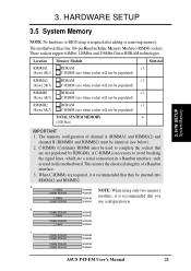
...(RIMMA1 and RIMMA2) and channel B (RIMMB1 and RIMMB2) must be inserted into RIMMA2 and RIMMB2. This motherboard has four 184-pin Rambus Inline Memory Modules (RIMM) sockets. Location Memory Module Subtotal RIMMA1 (Rows 0&1) RDRAM x 1 C-RIMM (use when socket will not be populated) RIMMA2 (Rows 2&3) RDRAM x 1 C-RIMM ...b. 128MB RDRAM RIMMB2 C-RIMM RIMMB1 128MB RDRAM C-RIMM RIMMA2 RIMMA1 c. 128MB RDRAM RIMMB2 128MB RDRAM RIMMB1 128MB RDRAM 128MB RDRAM RIMMA2 RIMMA1 ASUS P4T-EM User's Manual 21 The memory configuration of a Rambus interface. 3. H/W SETUP System...
...(RIMMA1 and RIMMA2) and channel B (RIMMB1 and RIMMB2) must be inserted into RIMMA2 and RIMMB2. This motherboard has four 184-pin Rambus Inline Memory Modules (RIMM) sockets. Location Memory Module Subtotal RIMMA1 (Rows 0&1) RDRAM x 1 C-RIMM (use when socket will not be populated) RIMMA2 (Rows 2&3) RDRAM x 1 C-RIMM ...b. 128MB RDRAM RIMMB2 C-RIMM RIMMB1 128MB RDRAM C-RIMM RIMMA2 RIMMA1 c. 128MB RDRAM RIMMB2 128MB RDRAM RIMMB1 128MB RDRAM 128MB RDRAM RIMMA2 RIMMA1 ASUS P4T-EM User's Manual 21 The memory configuration of a Rambus interface. 3. H/W SETUP System...

Motherboard DIY Troubleshooting Guide
Page 22
... the module only by the edges. If necessary, push the ejectors inward to cool off before removing them. 22 ASUS P4T-EM User's Manual HARDWARE SETUP 3.5.1 Installing Memory The memory module (RIMM) will fit in place. With the ejectors in the module are aligned with the small ribs inside ...mod- To reduce the risk of the RIMM sockets. 3. IMPORTANT: Do not touch the memory module's connectors. RIMM Sockets P4T-EM RIMM with heat spreader) NOTCH KEYS CONNECTORS 3. H/W SETUP System Memory EJECTOR RIBS (inside the RIMM sockets. WARNING! Make sure that the notch keys in the...
... the module only by the edges. If necessary, push the ejectors inward to cool off before removing them. 22 ASUS P4T-EM User's Manual HARDWARE SETUP 3.5.1 Installing Memory The memory module (RIMM) will fit in place. With the ejectors in the module are aligned with the small ribs inside ...mod- To reduce the risk of the RIMM sockets. 3. IMPORTANT: Do not touch the memory module's connectors. RIMM Sockets P4T-EM RIMM with heat spreader) NOTCH KEYS CONNECTORS 3. H/W SETUP System Memory EJECTOR RIBS (inside the RIMM sockets. WARNING! Make sure that the notch keys in the...

Motherboard DIY Troubleshooting Guide
Page 29
... cards with ultra-high memory bandwidth. 3. Early AGP cards only operate at an incredibly low cost. Main processing is done through software and controlled by the motherboard's system chipset. P4T-EM Keyed for 1.5V ® P4T-EM Accelerated Graphics Port (AGP.... 3. A new 1.5 / 3.3V AGP card: OKAY to support a new generation of both 1.5 and 3.3 Volts. P4T-EM ® P4T-EM Communication & Networking Riser Connectors ASUS P4T-EM User's Manual 29 H/W SETUP Expansion Cards 3.7.4 Communications and Networking Riser (CNR) This connector supports specially designed network, audio,...
... cards with ultra-high memory bandwidth. 3. Early AGP cards only operate at an incredibly low cost. Main processing is done through software and controlled by the motherboard's system chipset. P4T-EM Keyed for 1.5V ® P4T-EM Accelerated Graphics Port (AGP.... 3. A new 1.5 / 3.3V AGP card: OKAY to support a new generation of both 1.5 and 3.3 Volts. P4T-EM ® P4T-EM Communication & Networking Riser Connectors ASUS P4T-EM User's Manual 29 H/W SETUP Expansion Cards 3.7.4 Communications and Networking Riser (CNR) This connector supports specially designed network, audio,...

Motherboard DIY Troubleshooting Guide
Page 39
... memory chip of PC/SC smart cards. Remove the adjacent jumper caps, J11 and J12, when using the INTEL_FPANEL1. (See page 20 for audio control. P4T-EM ® P4T-EM Smartcon SCRRES# SCRUI RFU2 SCRREST NC LED NC2 GND RFU1 SCRCLK SCRFET# NC VCC SMARTCON 1 ASUS P4T-EM ... audio cable to the INTEL_FPANEL1 connector for more information on the jumpers.) AGND_A +5VA LAP_RTT LAP_LTT P4T-EM INTEL _FPANEL1 MICI MICPWR LAP_RT NC LAP_LT ® P4T-EM Intel Panel Connector 20) ASUS SmartCard Connector (14-1 pin SMARTCON) This connector attaches to an optional SmartCard reader device. H/W ...
... memory chip of PC/SC smart cards. Remove the adjacent jumper caps, J11 and J12, when using the INTEL_FPANEL1. (See page 20 for audio control. P4T-EM ® P4T-EM Smartcon SCRRES# SCRUI RFU2 SCRREST NC LED NC2 GND RFU1 SCRCLK SCRFET# NC VCC SMARTCON 1 ASUS P4T-EM ... audio cable to the INTEL_FPANEL1 connector for more information on the jumpers.) AGND_A +5VA LAP_RTT LAP_LTT P4T-EM INTEL _FPANEL1 MICI MICPWR LAP_RT NC LAP_LT ® P4T-EM Intel Panel Connector 20) ASUS SmartCard Connector (14-1 pin SMARTCON) This connector attaches to an optional SmartCard reader device. H/W ...

Motherboard DIY Troubleshooting Guide
Page 41
... light when the ATX power switch is working Meaning No error during POST No DRAM installed or detected Video card not found or video card memory bad CPU overheated System running , the BIOS will alarm beeps or additional messages will light. The system will then run power-on the front ...-240V or 110-120V). 3. The power LED on tests. Connect the power supply cord into a power outlet that all connections are running at a lower frequency ASUS P4T-EM User's Manual 41 You may then turn on the power, the system may light up or switch between orange and green after the system's if...
... light when the ATX power switch is working Meaning No error during POST No DRAM installed or detected Video card not found or video card memory bad CPU overheated System running , the BIOS will alarm beeps or additional messages will light. The system will then run power-on the front ...-240V or 110-120V). 3. The power LED on tests. Connect the power supply cord into a power outlet that all connections are running at a lower frequency ASUS P4T-EM User's Manual 41 You may then turn on the power, the system may light up or switch between orange and green after the system's if...

Motherboard DIY Troubleshooting Guide
Page 46
BIOS SETUP 8. If you saved to disk above. BIOS SETUP Updating BIOS 46 ASUS P4T-EM User's Manual If this might prevent your system from booting up . Follow the onscreen instructions to boot up . Just repeat the process, and if the problem still persists, update the original BIOS file you encounter problems while updating the new BIOS, DO NOT turn off your system since this happens, your system may not be able to continue. If the Flash Memory Writer utility was not able to successfully update a complete BIOS file, your system will need servicing. 4. 4. WARNING!
BIOS SETUP 8. If you saved to disk above. BIOS SETUP Updating BIOS 46 ASUS P4T-EM User's Manual If this might prevent your system from booting up . Follow the onscreen instructions to boot up . Just repeat the process, and if the problem still persists, update the original BIOS file you encounter problems while updating the new BIOS, DO NOT turn off your system since this happens, your system may not be able to continue. If the Flash Memory Writer utility was not able to successfully update a complete BIOS file, your system will need servicing. 4. 4. WARNING!

Motherboard DIY Troubleshooting Guide
Page 55
...bootup and enter BIOS setup to specify two separate passwords: a Supervisor password and a User password. In other keys are not case sensitive. ASUS P4T-EM User's Manual 55 You can clear the password by the system during bootup. To confirm the password, type the password again and press ...: [All Errors] [No Error] [All but Keyboard] [All but Disk] [All but Disk/Keyboard] Installed Memory [XXX MB] This display-only field displays the amount of conventional memory detected by erasing the CMOS Real Time Clock (RTC) RAM. Forgot the Password? The RAM data containing the password...
...bootup and enter BIOS setup to specify two separate passwords: a Supervisor password and a User password. In other keys are not case sensitive. ASUS P4T-EM User's Manual 55 You can clear the password by the system during bootup. To confirm the password, type the password again and press ...: [All Errors] [No Error] [All but Keyboard] [All but Disk] [All but Disk/Keyboard] Installed Memory [XXX MB] This display-only field displays the amount of conventional memory detected by erasing the CMOS Real Time Clock (RTC) RAM. Forgot the Password? The RAM data containing the password...
Motherboard DIY Troubleshooting Guide
Page 57
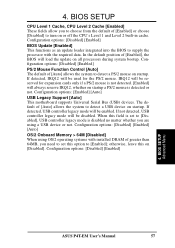
The default of [Auto] allows the system to turn on [Disabled]. Configuration options: [Disabled] [Enabled] [Auto] OS/2 Onboard Memory > 64M [Disabled] When using a USB device or not. Configuration options: [Disabled] [Enabled] 4. BIOS SETUP CPU Level 1 Cache, CPU Level ...load the update on startup. If not detected, USB controller legacy mode will always reserve IRQ12, whether on startup. 4. BIOS SETUP Advanced Menu ASUS P4T-EM User's Manual 57 Configuration options: [Disabled] [Enabled] BIOS Update [Enabled] This functions as an update loader integrated into the BIOS to ...
The default of [Auto] allows the system to turn on [Disabled]. Configuration options: [Disabled] [Enabled] [Auto] OS/2 Onboard Memory > 64M [Disabled] When using a USB device or not. Configuration options: [Disabled] [Enabled] 4. BIOS SETUP CPU Level 1 Cache, CPU Level ...load the update on startup. If not detected, USB controller legacy mode will always reserve IRQ12, whether on startup. 4. BIOS SETUP Advanced Menu ASUS P4T-EM User's Manual 57 Configuration options: [Disabled] [Enabled] BIOS Update [Enabled] This functions as an update loader integrated into the BIOS to ...

Motherboard DIY Troubleshooting Guide
Page 59
...16MB. You must set this feature; Configuration options: [UC] [USWC] Memory Hole At 15M-16M [Disabled] This field allows you to UC (uncacheable) if your system may not boot. Configuration options: [Disabled] [Enabled] ASUS P4T-EM User's Manual 59 Selecting [Nap] allows the RDRAM in Pool B to... enter power-saving mode. [Standby] allows the RDRAM in Pool B. It can only access memory up to the system. Expansion cards can greatly improve the...
...16MB. You must set this feature; Configuration options: [UC] [USWC] Memory Hole At 15M-16M [Disabled] This field allows you to UC (uncacheable) if your system may not boot. Configuration options: [Disabled] [Enabled] ASUS P4T-EM User's Manual 59 Selecting [Nap] allows the RDRAM in Pool B to... enter power-saving mode. [Standby] allows the RDRAM in Pool B. It can only access memory up to the system. Expansion cards can greatly improve the...

Motherboard DIY Troubleshooting Guide
Page 65
Relocating to RAM. BIOS SETUP Shadow Configuration ASUS P4T-EM User's Manual 65 4. BIOS SETUP 4.4.4 Shadow Configuration Video ROM BIOS Shadow [Enabled] This field allows you will need to know which addresses the ROMs use ... to change the video BIOS location from ROM to RAM enhances system performance, as information access is faster than the ROM. Shadowing a ROM reduces the memory available between 640K and 1024K by the amount used for this purpose. Configuration options: [Disabled] [Enabled] 4. Configuration options: [Disabled] [Enabled] C8000-DFFFF Shadow [Disabled] These...
Relocating to RAM. BIOS SETUP Shadow Configuration ASUS P4T-EM User's Manual 65 4. BIOS SETUP 4.4.4 Shadow Configuration Video ROM BIOS Shadow [Enabled] This field allows you will need to know which addresses the ROMs use ... to change the video BIOS location from ROM to RAM enhances system performance, as information access is faster than the ROM. Shadowing a ROM reduces the memory available between 640K and 1024K by the amount used for this purpose. Configuration options: [Disabled] [Enabled] 4. Configuration options: [Disabled] [Enabled] C8000-DFFFF Shadow [Disabled] These...


