
Motherboard DIY Troubleshooting Guide
Page 9
...): This connector supports a joystick or a game pad for a PS/2 keyboard. • Onboard LED: Signals AC power is okay. • ATX power connector. Supplies the MB with ATX power. • Microphone jack (optional): Pink jack connects a microphone. • Line In jack (optional): Light blue ...allows multiple PCI transfers from PCI master bus to four Ultra DMA/100/66, PIO Modes 3 & 4 IDE devices. 2. FEATURES Connections 2. ASUS P4T-E User's Manual 9 FEATURES 2.1.2 Connections • CPU socket: 478-pin surface mount, ZIF socket mPGA478 B. • PCI Expansion Slots: Provides...
...): This connector supports a joystick or a game pad for a PS/2 keyboard. • Onboard LED: Signals AC power is okay. • ATX power connector. Supplies the MB with ATX power. • Microphone jack (optional): Pink jack connects a microphone. • Line In jack (optional): Light blue ...allows multiple PCI transfers from PCI master bus to four Ultra DMA/100/66, PIO Modes 3 & 4 IDE devices. 2. FEATURES Connections 2. ASUS P4T-E User's Manual 9 FEATURES 2.1.2 Connections • CPU socket: 478-pin surface mount, ZIF socket mPGA478 B. • PCI Expansion Slots: Provides...
Motherboard DIY Troubleshooting Guide
Page 12
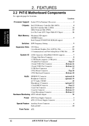
Location Processor Support Socket 478 for locations. FEATURES MB Components 2. FEATURES 2.2 P4T-E Motherboard Components See opposite page for Pentium 4 Processors 2 Chipsets Intel 850 Memory Controller Hub (MCH 4 Intel I/O Controller Hub 2... Top) 23 1 Line Out Connector Bottom) 23 1 Line In Connector Bottom) 23 1 Line Microphone Connector Bottom) 23 Hardware Monitoring ASUS onboard chipset 10 Power ATX Power Supply Connector 1 ATX 12V Power Supply Connector 3 Special Feature Auxillary Power Connector 6 Onboard LED 14 Form Factor ATX 12 ASUS P4T-E User's Manual 2.
Location Processor Support Socket 478 for locations. FEATURES MB Components 2. FEATURES 2.2 P4T-E Motherboard Components See opposite page for Pentium 4 Processors 2 Chipsets Intel 850 Memory Controller Hub (MCH 4 Intel I/O Controller Hub 2... Top) 23 1 Line Out Connector Bottom) 23 1 Line In Connector Bottom) 23 1 Line Microphone Connector Bottom) 23 Hardware Monitoring ASUS onboard chipset 10 Power ATX Power Supply Connector 1 ATX 12V Power Supply Connector 3 Special Feature Auxillary Power Connector 6 Onboard LED 14 Form Factor ATX 12 ASUS P4T-E User's Manual 2.
Motherboard DIY Troubleshooting Guide
Page 15
...System Management Bus Connector (5-1 pin) 19) TR1 p.40 Device Thermal Sensor Connector (2 pin) 20) ATXPWR, ATX12V, (AUXPWR) p.41 Power Supply Connector (20 pin, 4 pin) (6 pin) 21) PWRLED (PANEL) p.42 System Power LED Lead (3-1 pin) 22) KEYLOCK (PANEL) p.43 Keyboard Lock Switch Lead (2 pin) 23) SPEAKER (PANEL) p.44 System ...LED (PANEL) p.45 System Message LED (2 pin) 25) SMI (PANEL) p.46 System Management Interrupt Switch Lead (2 pin) 26) PWRSW (PANEL) p.47 ATX Power / Soft-Off Switch Lead (2 pin) 27) RESET (PANEL) p.48 Reset Switch Lead (2 pin) ASUS P4T-E User's Manual 15
...System Management Bus Connector (5-1 pin) 19) TR1 p.40 Device Thermal Sensor Connector (2 pin) 20) ATXPWR, ATX12V, (AUXPWR) p.41 Power Supply Connector (20 pin, 4 pin) (6 pin) 21) PWRLED (PANEL) p.42 System Power LED Lead (3-1 pin) 22) KEYLOCK (PANEL) p.43 Keyboard Lock Switch Lead (2 pin) 23) SPEAKER (PANEL) p.44 System ...LED (PANEL) p.45 System Message LED (2 pin) 25) SMI (PANEL) p.46 System Management Interrupt Switch Lead (2 pin) 26) PWRSW (PANEL) p.47 ATX Power / Soft-Off Switch Lead (2 pin) 27) RESET (PANEL) p.48 Reset Switch Lead (2 pin) ASUS P4T-E User's Manual 15
Motherboard DIY Troubleshooting Guide
Page 16
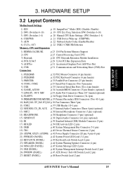
... least 8.5A on the +12V lead is required. Configure the BIOS parameter settings WARNING! H/W SETUP Getting Started 16 ASUS P4T-E User's Manual 3. Connect ribbon cables, panel wires, and power supply cables 6. HARDWARE SETUP 3.3 Hardware Setup Procedure IMPORTANT: Due to your motherboard, peripherals, and/or components. 3. Failure to do so may cause severe damage to...
... least 8.5A on the +12V lead is required. Configure the BIOS parameter settings WARNING! H/W SETUP Getting Started 16 ASUS P4T-E User's Manual 3. Connect ribbon cables, panel wires, and power supply cables 6. HARDWARE SETUP 3.3 Hardware Setup Procedure IMPORTANT: Due to your motherboard, peripherals, and/or components. 3. Failure to do so may cause severe damage to...

Motherboard DIY Troubleshooting Guide
Page 17
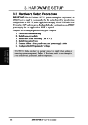
...are separated from static electricity, you should follow some precautions whenever you plug in or remove the ATX power connector on the inside. 2. H/W SETUP Motherboard Settings ASUS P4T-E User's Manual 17 HARDWARE SETUP 3.4 Motherboard Settings This section tells you do not have one, ...touch both of your computer when working on the motherboard. Hold components by the edges and try not to a metal object, such as the power supply case. 3. WARNING...
...are separated from static electricity, you should follow some precautions whenever you plug in or remove the ATX power connector on the inside. 2. H/W SETUP Motherboard Settings ASUS P4T-E User's Manual 17 HARDWARE SETUP 3.4 Motherboard Settings This section tells you do not have one, ...touch both of your computer when working on the motherboard. Hold components by the edges and try not to a metal object, such as the power supply case. 3. WARNING...
Motherboard DIY Troubleshooting Guide
Page 21
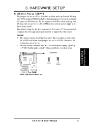
... stopped; The default setting for the three jumpers is 2-3 to select +5V (because not all computers have the appropriate power supply to CPU; H/W SETUP Motherboard Settings ASUS P4T-E User's Manual 21 NOTES: 1. USBPWR 2 1 +5VSB 3 2 +5V (Default) P4T-E P4T-E USB Device Wake Up 3. power supply in slow refresh; HARDWARE SETUP 4) USB Device Wake-up from S3 sleep state (no...
... stopped; The default setting for the three jumpers is 2-3 to select +5V (because not all computers have the appropriate power supply to CPU; H/W SETUP Motherboard Settings ASUS P4T-E User's Manual 21 NOTES: 1. USBPWR 2 1 +5VSB 3 2 +5V (Default) P4T-E P4T-E USB Device Wake Up 3. power supply in slow refresh; HARDWARE SETUP 4) USB Device Wake-up from S3 sleep state (no...

Motherboard DIY Troubleshooting Guide
Page 29
... your computer system's cover and the bracket plate on the slot with the screw you intend to both your power supply when adding or removing expansion Cards or other system components. H/W SETUP Expansion Cards ASUS P4T-E User's Manual 29 Carefully align the card's connectors and press firmly. 4. 3. Unplug your motherboard and expansion cards. (See...
... your computer system's cover and the bracket plate on the slot with the screw you intend to both your power supply when adding or removing expansion Cards or other system components. H/W SETUP Expansion Cards ASUS P4T-E User's Manual 29 Carefully align the card's connectors and press firmly. 4. 3. Unplug your motherboard and expansion cards. (See...

Motherboard DIY Troubleshooting Guide
Page 39
... Activity LED HDDLED TIP: If the case-mounted LED does not light, try reversing the 2-pin plug. ASUS P4T-E User's Manual 39 Read and write activity by devices connected to the Primary/Secondary IDE and Primary/ Secondary ATA100 connectors will ...Standard and Consumer Infrared (SIR) Module Connector (5-pin IR) This connector supports an optional wireless transmitting and receiving infrared module. IR 1 P4T-E P4T-E Infrared Module Connector Front View Back View IRTX +5V GND (NC) IRRX 17) IDE Activity LED (2-pin HDLED) This connector supplies power to the cabinet's IDE activity LED.
... Activity LED HDDLED TIP: If the case-mounted LED does not light, try reversing the 2-pin plug. ASUS P4T-E User's Manual 39 Read and write activity by devices connected to the Primary/Secondary IDE and Primary/ Secondary ATA100 connectors will ...Standard and Consumer Infrared (SIR) Module Connector (5-pin IR) This connector supports an optional wireless transmitting and receiving infrared module. IR 1 P4T-E P4T-E Infrared Module Connector Front View Back View IRTX +5V GND (NC) IRRX 17) IDE Activity LED (2-pin HDLED) This connector supplies power to the cabinet's IDE activity LED.
Motherboard DIY Troubleshooting Guide
Page 40
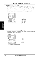
... pin SMB) This connector allows you have a device (e.g. TR1 Thermal P4T-E Sensor Connector P4T-E Thermal Sensor Connector 40 ASUS P4T-E User's Manual that is a multi-device bus; P4T-E P4T-E SMBus Connector SMB 1 FLOATING SMBCLK Ground SMBDATA +3V 19) Device Thermal... Sensor Connector (2-pin TR1) If you to the same bus and each one can act as a master by means of an I2C bus, which is , multiple chips can be connected to connect SMBus (System Management Bus) devices. power supply...
... pin SMB) This connector allows you have a device (e.g. TR1 Thermal P4T-E Sensor Connector P4T-E Thermal Sensor Connector 40 ASUS P4T-E User's Manual that is a multi-device bus; P4T-E P4T-E SMBus Connector SMB 1 FLOATING SMBCLK Ground SMBDATA +3V 19) Device Thermal... Sensor Connector (2-pin TR1) If you to the same bus and each one can act as a master by means of an I2C bus, which is , multiple chips can be connected to connect SMBus (System Management Bus) devices. power supply...

Motherboard DIY Troubleshooting Guide
Page 41
... lead and at least 720mA +5VSB. For WakeOn-LAN support, your ATX 12V power supply (minimum recommended wattage: 230 watts; 300W for a fully-configured system) can supply at least 20 amperes on the +5-volt standby lead (+5VSB). H/W SETUP Connectors ASUS P4T-E User's Manual 41 Push down firmly and make sure the pins are aligned. Your...
... lead and at least 720mA +5VSB. For WakeOn-LAN support, your ATX 12V power supply (minimum recommended wattage: 230 watts; 300W for a fully-configured system) can supply at least 20 amperes on the +5-volt standby lead (+5VSB). H/W SETUP Connectors ASUS P4T-E User's Manual 41 Push down firmly and make sure the pins are aligned. Your...
Motherboard DIY Troubleshooting Guide
Page 42
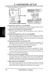
... Connector +5 V PLED Keylock Ground +5V Ground Ground Speaker +5 V MLED ExtSMI# Ground PWR Ground Reset Ground 3. The system power LED shows the status of the system's power supply. 42 ASUS P4T-E User's Manual The LED will switch the system between ON and SOFT OFF. This function requires an ACPI OS and driver support. 25) System Management...
... Connector +5 V PLED Keylock Ground +5V Ground Ground Speaker +5 V MLED ExtSMI# Ground PWR Ground Reset Ground 3. The system power LED shows the status of the system's power supply. 42 ASUS P4T-E User's Manual The LED will switch the system between ON and SOFT OFF. This function requires an ACPI OS and driver support. 25) System Management...

Motherboard DIY Troubleshooting Guide
Page 43
...it complies with the last device on the back of your system case according to your devices in the following order: a. For ATX power supplies, you turn on the power, the system may then turn on the front panel of the case. 6. The LED on the front of the system case will ...detected Video card not found or video card memory bad CPU overheated System running at a lower frequency ASUS P4T-E User's Manual 43 While the tests are off (in some systems, marked with ), and the power input voltage is equipped with the standard used in an endless loop One long beep followed by ...
...it complies with the last device on the back of your system case according to your devices in the following order: a. For ATX power supplies, you turn on the power, the system may then turn on the front panel of the case. 6. The LED on the front of the system case will ...detected Video card not found or video card memory bad CPU overheated System running at a lower frequency ASUS P4T-E User's Manual 43 While the tests are off (in some systems, marked with ), and the power input voltage is equipped with the standard used in an endless loop One long beep followed by ...

Motherboard DIY Troubleshooting Guide
Page 44
... the instructions in 4. BIOS SETUP. * Powering Off your computer: You must first exit or shut down to enter BIOS setup. If you can now safely turn off after exiting or shutting down . During power-on, hold down your operating system before ...power switch after Windows shuts down your computer" will not appear when shutting down the computer? The power supply should turn off the power switch. 3. For ATX power supplies, you use Windows 9X, click the Start button, click Shut Down, and then click Shut down with ATX power supplies. 3. H/W SETUP Powering Up 44 ASUS P4T...
... the instructions in 4. BIOS SETUP. * Powering Off your computer: You must first exit or shut down to enter BIOS setup. If you can now safely turn off after exiting or shutting down . During power-on, hold down your operating system before ...power switch after Windows shuts down your computer" will not appear when shutting down the computer? The power supply should turn off the power switch. 3. For ATX power supplies, you use Windows 9X, click the Start button, click Shut Down, and then click Shut down with ATX power supplies. 3. H/W SETUP Powering Up 44 ASUS P4T...

Motherboard DIY Troubleshooting Guide
Page 70
... when the external modem receives a call while the computer is in Soft-off and then back on the first try. BIOS SETUP Power Up Control AC PWR Loss Restart [Disabled] This allows you to set whether you want your system to reboot after the.... Configuration options: [Disabled] [Enabled] IMPORTANT: This feature requires an optional network interface with Wake-OnLAN and an ATX power supply with at least 720mA +5V standby power. 70 ASUS P4T-E User's Manual BIOS SETUP 4.5.1 Power Up Control 4. Configuration options: [Disabled] [Enabled] Wake On LAN or PCI Modem card [Disabled] Wake-On-LAN or a ...
... when the external modem receives a call while the computer is in Soft-off and then back on the first try. BIOS SETUP Power Up Control AC PWR Loss Restart [Disabled] This allows you to set whether you want your system to reboot after the.... Configuration options: [Disabled] [Enabled] IMPORTANT: This feature requires an optional network interface with Wake-OnLAN and an ATX power supply with at least 720mA +5V standby power. 70 ASUS P4T-E User's Manual BIOS SETUP 4.5.1 Power Up Control 4. Configuration options: [Disabled] [Enabled] Wake On LAN or PCI Modem card [Disabled] Wake-On-LAN or a ...
Motherboard DIY Troubleshooting Guide
Page 71
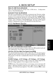
...Hardware Monitor found an error. The presence of the fans is able to detect the CPU fan speed, power supply fan speed, and the chassis fan speed in rotations per minute (RPM). Enter Power setup menu for details". VCORE Voltage, +3.3V Voltage, +5V Voltage, +12V Voltage The onboard hardware ... Monitor MB, CPU, TR Temperature [xxxC/xxxF] The onboard hardware monitor is able to detect the voltage output by the onboard voltage regulators. ASUS P4T-E User's Manual 71 BIOS SETUP Wake On USB Device [Disabled] Wake On USB permits PC bootup from a USB device. You may configure...
...Hardware Monitor found an error. The presence of the fans is able to detect the CPU fan speed, power supply fan speed, and the chassis fan speed in rotations per minute (RPM). Enter Power setup menu for details". VCORE Voltage, +3.3V Voltage, +5V Voltage, +12V Voltage The onboard hardware ... Monitor MB, CPU, TR Temperature [xxxC/xxxF] The onboard hardware monitor is able to detect the voltage output by the onboard voltage regulators. ASUS P4T-E User's Manual 71 BIOS SETUP Wake On USB Device [Disabled] Wake On USB permits PC bootup from a USB device. You may configure...


