
Motherboard DIY Troubleshooting Guide
Page 7
...package is divided into the following sections: 1. Intructions on setting up the BIOS Intructions on setting up the included software Reference material for (1) 5.25" and (2) 3.5" floppy disk drives (1) COM Port Bracket and Cable (1) ASUS 2-port USB connector set with bracket (1) I/O port bracket (1) Bag of spare jumpers (1) Support drivers and utilities (1) This Motherboard User's Manual (1) CPU Retention Module (1) CD Audio Optional Items ASUS IrDA-compliant infrared module ASUS PCI-L101 Wake-On-LAN 10/ 1000 ethernet card ASUS P4T-CM User's Manual 7 INTRODUCTION 2. 1.
...package is divided into the following sections: 1. Intructions on setting up the BIOS Intructions on setting up the included software Reference material for (1) 5.25" and (2) 3.5" floppy disk drives (1) COM Port Bracket and Cable (1) ASUS 2-port USB connector set with bracket (1) I/O port bracket (1) Bag of spare jumpers (1) Support drivers and utilities (1) This Motherboard User's Manual (1) CPU Retention Module (1) CD Audio Optional Items ASUS IrDA-compliant infrared module ASUS PCI-L101 Wake-On-LAN 10/ 1000 ethernet card ASUS P4T-CM User's Manual 7 INTRODUCTION 2. 1.
Motherboard DIY Troubleshooting Guide
Page 8
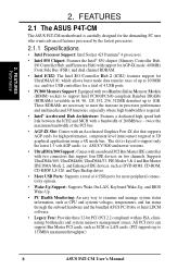
..., PIO Modes 3 & 4 and Bus Master IDE DMA Mode 2, and Enhanced IDE devices, such as SCSI or LAN cards. (PCI supports up to 133MB/s maximum throughput.) 8 ASUS P4T-CM User's Manual and dual channel RDRAM. • Intel ICH2: The Intel I /O Controller Hub, and Firmware Hub) with an Accelerated Graphics Port 4X slot that support four IDE devices on two channels. FEATURES Performance 2. FEATURES 2.1 The ASUS P4T-CM The ASUS P4T-CM motherboard is required. • Intel® Accelerated Hub Architecture: Features a dedicated high speed hub link...
..., PIO Modes 3 & 4 and Bus Master IDE DMA Mode 2, and Enhanced IDE devices, such as SCSI or LAN cards. (PCI supports up to 133MB/s maximum throughput.) 8 ASUS P4T-CM User's Manual and dual channel RDRAM. • Intel ICH2: The Intel I /O Controller Hub, and Firmware Hub) with an Accelerated Graphics Port 4X slot that support four IDE devices on two channels. FEATURES Performance 2. FEATURES 2.1 The ASUS P4T-CM The ASUS P4T-CM motherboard is required. • Intel® Accelerated Hub Architecture: Features a dedicated high speed hub link...

Motherboard DIY Troubleshooting Guide
Page 10
... in two channels. 2. FEATURES 2.1.3 Performance Features • High-Speed Data Transfer Interface: Onboard IDE Bus Master controller with a peak bandwidth of the motherboard meet the stringent requirements for PC 99 certification. Supports UltraDMA/100/66, UltraDMA/33 (IDE DMA Mode 2), PIO Modes 3 & 4, and supports Enhanced IDE devices, such as required by PC 99. 10 ASUS P4T-CM User's Manual While PC100 SDRAM modules operate at 100MHz with two connectors that you...
... in two channels. 2. FEATURES 2.1.3 Performance Features • High-Speed Data Transfer Interface: Onboard IDE Bus Master controller with a peak bandwidth of the motherboard meet the stringent requirements for PC 99 certification. Supports UltraDMA/100/66, UltraDMA/33 (IDE DMA Mode 2), PIO Modes 3 & 4, and supports Enhanced IDE devices, such as required by PC 99. 10 ASUS P4T-CM User's Manual While PC100 SDRAM modules operate at 100MHz with two connectors that you...
Motherboard DIY Troubleshooting Guide
Page 11
... CHASSIS fans can be powered ON using your keyboard or mouse click. Suggestions will give the user information on managing their limited resources more efficiently. • Dual Function Power Button: Through BIOS, the power button can be enabled or disabled through BIOS setup to allow the computer to enable Pentium 4 processors auto throttling function. When auto throttling is a new technology to be monitored for RPM and failure. The onboard hardware ASUS ASIC in 3.8 Connectors for future processors...
... CHASSIS fans can be powered ON using your keyboard or mouse click. Suggestions will give the user information on managing their limited resources more efficiently. • Dual Function Power Button: Through BIOS, the power button can be enabled or disabled through BIOS setup to allow the computer to enable Pentium 4 processors auto throttling function. When auto throttling is a new technology to be monitored for RPM and failure. The onboard hardware ASUS ASIC in 3.8 Connectors for future processors...
Motherboard DIY Troubleshooting Guide
Page 12
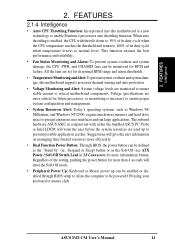
... 1 PS/2 Mouse Connector Top) 23 1 PS/2 Keyboard Connector Bottom) 23 Audio AC'97 Audio CODEC 16 1 Game/MIDI Connector Top) 19 1 Line Out Connector Bottom) 19 1 Line In Connector Bottom) 19 1 Line Microphone Connector Bottom) 19 Network Features Realtek LAN Chip Controller optional) 18 LAN (RJ-45) Connector optional) (Top) 22 Wake-On-LAN Connector 14 Hardware Monitoring Low Pin Count (LPC) Winbond Multi-I/O Chipset 4 Power ATX Power Supply Connector 6 ATX 12V Power Supply Connector 6 Special Feature 1 iPanel Header 8 Form Factor MicroATX 12 ASUS P4T-CM User's Manual 2.
... 1 PS/2 Mouse Connector Top) 23 1 PS/2 Keyboard Connector Bottom) 23 Audio AC'97 Audio CODEC 16 1 Game/MIDI Connector Top) 19 1 Line Out Connector Bottom) 19 1 Line In Connector Bottom) 19 1 Line Microphone Connector Bottom) 19 Network Features Realtek LAN Chip Controller optional) 18 LAN (RJ-45) Connector optional) (Top) 22 Wake-On-LAN Connector 14 Hardware Monitoring Low Pin Count (LPC) Winbond Multi-I/O Chipset 4 Power ATX Power Supply Connector 6 ATX 12V Power Supply Connector 6 Special Feature 1 iPanel Header 8 Form Factor MicroATX 12 ASUS P4T-CM User's Manual 2.
Motherboard DIY Troubleshooting Guide
Page 15
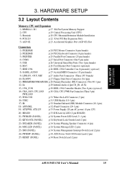
... pin) 19) ATXPWR, ATX12V p.33 Power Supply (20 pin AC power) (4 pin 12V) 20) HDLED p.33 IDE Activity LED (2 pin HDLED) 21) PWRLED (PANEL) p.34 System Power LED Lead (3 -1 pin) 22) KEYLOCK (PANEL) p.34 Keyboard Lock Switch Lead (2 pin) 23) SPEAKER (PANEL) p.34 System Warning Speaker Connector (4 pin) 24) MSG.LED (PANEL) p.34 System Message LED (2 pin) 25) SMI (PANEL) p.34 System Management Interrupt Switch Lead (2 pin) 26) PWRSW (PANEL) p.34 ATX Power / Soft-Off Switch Lead (2 pin) 27) RESET (PANEL) p.34 Reset Switch Lead (2 pin) ASUS P4T-CM User's Manual 15 H/W SETUP Layout...
... pin) 19) ATXPWR, ATX12V p.33 Power Supply (20 pin AC power) (4 pin 12V) 20) HDLED p.33 IDE Activity LED (2 pin HDLED) 21) PWRLED (PANEL) p.34 System Power LED Lead (3 -1 pin) 22) KEYLOCK (PANEL) p.34 Keyboard Lock Switch Lead (2 pin) 23) SPEAKER (PANEL) p.34 System Warning Speaker Connector (4 pin) 24) MSG.LED (PANEL) p.34 System Message LED (2 pin) 25) SMI (PANEL) p.34 System Management Interrupt Switch Lead (2 pin) 26) PWRSW (PANEL) p.34 ATX Power / Soft-Off Switch Lead (2 pin) 27) RESET (PANEL) p.34 Reset Switch Lead (2 pin) ASUS P4T-CM User's Manual 15 H/W SETUP Layout...

Motherboard DIY Troubleshooting Guide
Page 22
... necessary software drivers for your motherboard and expansion cards (see 3.3 Hardware Setup Procedure for more information). 3.6.1 Expansion Card Installation Procedure 1. Standard Interrupt Assignments IRQ Priority Standard Function 0 1 System Timer 1 2 Keyboard Controller 2 N/A Programmable Interrupt 3* 11 Communications Port (COM2) 4* 12 Communications Port (COM1) 5* 13 Sound Card (sometimes LPT2) 6 14 Floppy Disk Controller 7* 15 Printer Port (LPT1) 8 3 System CMOS/Real Time Clock 9* 4 ACPI Mode when enabled 10* 5 IRQ Holder for PCI Steering...
... necessary software drivers for your motherboard and expansion cards (see 3.3 Hardware Setup Procedure for more information). 3.6.1 Expansion Card Installation Procedure 1. Standard Interrupt Assignments IRQ Priority Standard Function 0 1 System Timer 1 2 Keyboard Controller 2 N/A Programmable Interrupt 3* 11 Communications Port (COM2) 4* 12 Communications Port (COM1) 5* 13 Sound Card (sometimes LPT2) 6 14 Floppy Disk Controller 7* 15 Printer Port (LPT1) 8 3 System CMOS/Real Time Clock 9* 4 ACPI Mode when enabled 10* 5 IRQ Holder for PCI Steering...

Motherboard DIY Troubleshooting Guide
Page 31
...-LAN Connector Ground 16) USB Headers (10-1 pin USB2) If the USB Ports on your chassis. IMPORTANT: Requires an ATX power supply with a Wake-On-LAN output. P4T-CM ® P4T-CM USB Headers USB2 10 6 5 1 1: USB Power 2: USBP2- 3: USBP2+ 4: GND 5: NC 6: USB Power 7: USBP3- 8: USBP3+ 9: GND ASUS P4T-CM User's Manual 31 Connect the 10-1 pin ribbon cable from the provided 2-port USB connector set to the midboard 10-1 pin USB header and mount the USB connector set to an open slot on the back panels are inadequate, a USB header is received through the LAN card. H/W SETUP...
...-LAN Connector Ground 16) USB Headers (10-1 pin USB2) If the USB Ports on your chassis. IMPORTANT: Requires an ATX power supply with a Wake-On-LAN output. P4T-CM ® P4T-CM USB Headers USB2 10 6 5 1 1: USB Power 2: USBP2- 3: USBP2+ 4: GND 5: NC 6: USB Power 7: USBP3- 8: USBP3+ 9: GND ASUS P4T-CM User's Manual 31 Connect the 10-1 pin ribbon cable from the provided 2-port USB connector set to the midboard 10-1 pin USB header and mount the USB connector set to an open slot on the back panels are inadequate, a USB header is received through the LAN card. H/W SETUP...

Motherboard DIY Troubleshooting Guide
Page 34
... system's power supply. 34 ASUS P4T-CM User's Manual The LED will switch the system between ON and SOFT OFF. Pushing the switch while in use. The system power LED shows the status of the system's power. 27) Reset Switch Lead (2-pin RESET) This 2-pin connector connects to the case-mounted reset switch for more than 4 seconds will allow you to this lead. HARDWARE SETUP The following diagram is controlled by a momentary switch connected to hear system beeps and warnings...
... system's power supply. 34 ASUS P4T-CM User's Manual The LED will switch the system between ON and SOFT OFF. Pushing the switch while in use. The system power LED shows the status of the system's power. 27) Reset Switch Lead (2-pin RESET) This 2-pin connector connects to the case-mounted reset switch for more than 4 seconds will allow you to this lead. HARDWARE SETUP The following diagram is controlled by a momentary switch connected to hear system beeps and warnings...
Motherboard DIY Troubleshooting Guide
Page 35
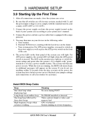
... following order: a. Your monitor b. The system will light. Be sure that is working Meaning No error during POST No DRAM installed or detected Video card not found or video card memory bad CPU overheated System running , the BIOS will alarm beeps or additional messages will light when the ATX power switch is set to comply with a surge protector. 5. For ATX power supplies, you turn on the power, the system may then turn on the chain) c. If...
... following order: a. Your monitor b. The system will light. Be sure that is working Meaning No error during POST No DRAM installed or detected Video card not found or video card memory bad CPU overheated System running , the BIOS will alarm beeps or additional messages will light when the ATX power switch is set to comply with a surge protector. 5. For ATX power supplies, you turn on the power, the system may then turn on the chain) c. If...
Motherboard DIY Troubleshooting Guide
Page 37
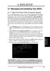
... reboot using a floppy. 3. BIOS SETUP Updating BIOS IMPORTANT! Type FORMAT A:/S at the DOS prompt to run AFLASH. 4. NOTE: AFLASH works only in DOS mode. Reboot your CDROM drive) to copy AFLASH.EXE to the just created boot disk. This file works only in DOS mode. If "unknown" is displayed after Flash Memory:, the memory chip is either not programmable or is a Flash Memory Writer utility that you save a copy of your hard drive. ASUS A7A266 User's Manual 37...
... reboot using a floppy. 3. BIOS SETUP Updating BIOS IMPORTANT! Type FORMAT A:/S at the DOS prompt to run AFLASH. 4. NOTE: AFLASH works only in DOS mode. Reboot your CDROM drive) to copy AFLASH.EXE to the just created boot disk. This file works only in DOS mode. If "unknown" is displayed after Flash Memory:, the memory chip is either not programmable or is a Flash Memory Writer utility that you save a copy of your hard drive. ASUS A7A266 User's Manual 37...
Motherboard DIY Troubleshooting Guide
Page 51
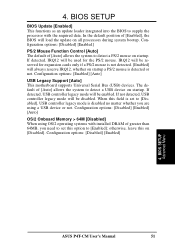
... [Disabled]. The default of [Enabled], the BIOS will be disabled. otherwise, leave this field is set this option to detect a USB device on startup a PS/2 mouse is detected or not. When this on all processors during system bootup. 4. BIOS SETUP BIOS Update [Enabled] This functions as an update loader integrated into the BIOS to supply the processor with installed DRAM of [Auto] allows the system to [Disabled], USB controller legacy mode is not detected. [Enabled] will be enabled. BIOS SETUP Advanced Menu ASUS P4T-CM User's Manual...
... [Disabled]. The default of [Enabled], the BIOS will be disabled. otherwise, leave this field is set this option to detect a USB device on startup a PS/2 mouse is detected or not. When this on all processors during system bootup. 4. BIOS SETUP BIOS Update [Enabled] This functions as an update loader integrated into the BIOS to supply the processor with installed DRAM of [Auto] allows the system to [Disabled], USB controller legacy mode is not detected. [Enabled] will be enabled. BIOS SETUP Advanced Menu ASUS P4T-CM User's Manual...

Motherboard DIY Troubleshooting Guide
Page 55
...use it, leave it is available. Onboard FDC Swap A&B [No Swap] This option selects drive letter assignments. Configuration options: [3F8H/IRQ4] [2F8H/IRQ3] [3E8H/IRQ4] [2E8H/ IRQ10] [Disabled] ASUS P4T-CM User's Manual 55 Configuration options; [Auto] [Disabled] Onboard Lan Controller [Enabled] (only on the default setting. The setup default [R/W] allows both reads and writes. BIOS will automatically activate the Audio Controller if it on model with LAN) This motherboard features an integrated LAN controller. BIOS SETUP 4.4.2 I /O Device Config Onboard AC97 Controller [Auto...
...use it, leave it is available. Onboard FDC Swap A&B [No Swap] This option selects drive letter assignments. Configuration options: [3F8H/IRQ4] [2F8H/IRQ3] [3E8H/IRQ4] [2E8H/ IRQ10] [Disabled] ASUS P4T-CM User's Manual 55 Configuration options; [Auto] [Disabled] Onboard Lan Controller [Enabled] (only on the default setting. The setup default [R/W] allows both reads and writes. BIOS will automatically activate the Audio Controller if it on model with LAN) This motherboard features an integrated LAN controller. BIOS SETUP 4.4.2 I /O Device Config Onboard AC97 Controller [Auto...

Motherboard DIY Troubleshooting Guide
Page 57
... for best performance vs. Configuration options: [Disabled] [Enabled] Primary VGA BIOS [PCI Card] If your primary card. The setting [Enabled] should correct this on default setting for each PCI slot. Configuration options: [PCI Card] [AGP Card] Onboard LAN Boot ROM [Disabled] Configuration options; [Disabled] [Enabled] ASUS P4T-CM User's Manual 57 Otherwise, leave this problem. BIOS SETUP 4.4.3 PCI Configuration 4. USB Function [Enabled] This motherboard supports Universal Serial Bus (USB) devices. Set to [Enabled] if you to select which utilizes auto-routing to use .
... for best performance vs. Configuration options: [Disabled] [Enabled] Primary VGA BIOS [PCI Card] If your primary card. The setting [Enabled] should correct this on default setting for each PCI slot. Configuration options: [PCI Card] [AGP Card] Onboard LAN Boot ROM [Disabled] Configuration options; [Disabled] [Enabled] ASUS P4T-CM User's Manual 57 Otherwise, leave this problem. BIOS SETUP 4.4.3 PCI Configuration 4. USB Function [Enabled] This motherboard supports Universal Serial Bus (USB) devices. Set to [Enabled] if you to select which utilizes auto-routing to use .

Motherboard DIY Troubleshooting Guide
Page 68
SOFTWARE SETUP 5.3 P4T-CM Motherboard Support CD NOTE: The support CD contents are subject to monitor the Client system. To begin using your support CD disc, just insert it into your CD-ROM drive is used in Windows for LDCM Vx.xx: Installs a utility that remotely flashes a client PC's BIOS and is drive E:). 5.3.1 Installation Menu 5. S/W SETUP Support CD • INF Update Utility for Intel 850 Chipset: Installs INF files in conjunction with LDCM Client software. • Intel LDCM Client Setup: Installs Intel...
SOFTWARE SETUP 5.3 P4T-CM Motherboard Support CD NOTE: The support CD contents are subject to monitor the Client system. To begin using your support CD disc, just insert it into your CD-ROM drive is used in Windows for LDCM Vx.xx: Installs a utility that remotely flashes a client PC's BIOS and is drive E:). 5.3.1 Installation Menu 5. S/W SETUP Support CD • INF Update Utility for Intel 850 Chipset: Installs INF files in conjunction with LDCM Client software. • Intel LDCM Client Setup: Installs Intel...

Motherboard DIY Troubleshooting Guide
Page 69
..., BIOS version, and CPU. • Browse Support CD: Allows you to view the contents of the CD. • ReadMe: Allows you to view user's manuals saved in PDF format. 5. S/W SETUP Support CD ASUS P4T-CM User's Manual 69 SOFTWARE SETUP • Adobe Acrobat Reader Vx.x: Installs the Adobe Acrobat Reader software necessary to view the support CD file list and contact information. • Exit: Exits the CD installation menu. (TO RETURN TO THE MAIN MENU...
..., BIOS version, and CPU. • Browse Support CD: Allows you to view the contents of the CD. • ReadMe: Allows you to view user's manuals saved in PDF format. 5. S/W SETUP Support CD ASUS P4T-CM User's Manual 69 SOFTWARE SETUP • Adobe Acrobat Reader Vx.x: Installs the Adobe Acrobat Reader software necessary to view the support CD file list and contact information. • Exit: Exits the CD installation menu. (TO RETURN TO THE MAIN MENU...

Motherboard DIY Troubleshooting Guide
Page 81
... OFF peripherals such as CD-ROMs, network cards, hard disk drives, and printers, as well as consumer devices connected to -point cable-connected virtual bus. ASUS P4T-CM User's Manual 81 AC97 (Audio Codec '97) AC '97 is a set of personal computers using the provided utility to consumer electronics devices. The BIOS can have one of data used by the user through the BIOS Setup program. APPENDIX Glossary 7. The specification defines new cost-effective options to help both a back...
... OFF peripherals such as CD-ROMs, network cards, hard disk drives, and printers, as well as consumer devices connected to -point cable-connected virtual bus. ASUS P4T-CM User's Manual 81 AC97 (Audio Codec '97) AC '97 is a set of personal computers using the provided utility to consumer electronics devices. The BIOS can have one of data used by the user through the BIOS Setup program. APPENDIX Glossary 7. The specification defines new cost-effective options to help both a back...

Motherboard DIY Troubleshooting Guide
Page 83
... Interconnect Local Bus) PCI bus is a standard widely used on the bus. PS/2 Port PS/2 ports are designed to reflect these changes. However, configuration of ISA cards is always ON but appears OFF and responds immediately to work simultaneously. RDRAM is configured to 1.6GB of memory and I /O devices. ASUS P4T-CM User's Manual 83 The POST checks system memory, the motherboard circuitry, the display, the keyboard, the diskette drive, and other requests. RDRAM (Rambus DRAM) Developed...
... Interconnect Local Bus) PCI bus is a standard widely used on the bus. PS/2 Port PS/2 ports are designed to reflect these changes. However, configuration of ISA cards is always ON but appears OFF and responds immediately to work simultaneously. RDRAM is configured to 1.6GB of memory and I /O devices. ASUS P4T-CM User's Manual 83 The POST checks system memory, the motherboard circuitry, the display, the keyboard, the diskette drive, and other requests. RDRAM (Rambus DRAM) Developed...

Motherboard DIY Troubleshooting Guide
Page 84
... is a version optimized for video cards, and main memory for the next time the CPU talks to the memory. The traditional IDE transfer only uses one edge of the data stroke as Ultra DMA/66, is under current PCI local bus environment USB (Universal Serial Bus) A 4-pin serial cable bus that allows up to 127 plug and play computer peripherals such as keyboard, mouse, joystick, scanner, printer, modem, and monitor to...
... is a version optimized for video cards, and main memory for the next time the CPU talks to the memory. The traditional IDE transfer only uses one edge of the data stroke as Ultra DMA/66, is under current PCI local bus environment USB (Universal Serial Bus) A 4-pin serial cable bus that allows up to 127 plug and play computer peripherals such as keyboard, mouse, joystick, scanner, printer, modem, and monitor to...

Motherboard DIY Troubleshooting Guide
Page 86
... Onboard PCI IDE Enable 54 Onboard Serial Port 1 55 Onboard Serial Port 2 55 OS/2 Onboard Memory > 64M 51 Other Boot Device Select 63 P Parallel Port Connector 25 Parallel Port Mode 56 PCI Latency Timer 57 PCI/VGA Palette Snoop 57 PIO Mode 47 Plug & Play O/S 64 Power Management 60 PowerPlayer SE Using 77 Procedures CPU Installation 19 Expansion Card Installation 22 Updating BIOS 38 PS/2 Keyboard Connector 24 PS/2 Mouse Connector 24 PWR Up On Modem Act 61 Q Quick Power On Self Test 64 R Removable Device 63 Reset Switch...
... Onboard PCI IDE Enable 54 Onboard Serial Port 1 55 Onboard Serial Port 2 55 OS/2 Onboard Memory > 64M 51 Other Boot Device Select 63 P Parallel Port Connector 25 Parallel Port Mode 56 PCI Latency Timer 57 PCI/VGA Palette Snoop 57 PIO Mode 47 Plug & Play O/S 64 Power Management 60 PowerPlayer SE Using 77 Procedures CPU Installation 19 Expansion Card Installation 22 Updating BIOS 38 PS/2 Keyboard Connector 24 PS/2 Mouse Connector 24 PWR Up On Modem Act 61 Q Quick Power On Self Test 64 R Removable Device 63 Reset Switch...


