
P4S8X User Manual
Page 2
... A PARTICULAR PURPOSE. No part of the manual revision number. ii For previous or updated manuals, BIOS, drivers, or product release information, contact ASUS at: http://www.asus.com or through any means, except documentation kept by the digit before and after the period of ...means indicated on the product itself. or (2) the serial number of ASUSTeK COMPUTER INC. ("ASUS"). Checklist P4S8X E1120 Sepetember 2002 Copyright © 2002 ASUSTeK COMPUTER INC. IN NO EVENT SHALL ASUS, ITS DIRECTORS, OFFICERS, EMPLOYEES OR AGENTS BE LIABLE FOR ANY INDIRECT, SPECIAL, INCIDENTAL, OR...
... A PARTICULAR PURPOSE. No part of the manual revision number. ii For previous or updated manuals, BIOS, drivers, or product release information, contact ASUS at: http://www.asus.com or through any means, except documentation kept by the digit before and after the period of ...means indicated on the product itself. or (2) the serial number of ASUSTeK COMPUTER INC. ("ASUS"). Checklist P4S8X E1120 Sepetember 2002 Copyright © 2002 ASUSTeK COMPUTER INC. IN NO EVENT SHALL ASUS, ITS DIRECTORS, OFFICERS, EMPLOYEES OR AGENTS BE LIABLE FOR ANY INDIRECT, SPECIAL, INCIDENTAL, OR...
P4S8X User Manual
Page 3
... information on the motherboard support CD ROM. • Appendix and Glossary. Detailed descriptions of contents on BIOS beep codes. • Chapter 4: BIOS setup. Optional components and technical definitions. • Index Conventions used throughout this guide To make sure ...BIOS firmware. IMPORTANT! WARNING! Information to prevent damage to complete a task. iii A summary of product features and special attributes of the following symbols used in this manual. CAUTION! How this guide This user manual contains complete information for installing the ASUS P4S8X...
... information on the motherboard support CD ROM. • Appendix and Glossary. Detailed descriptions of contents on BIOS beep codes. • Chapter 4: BIOS setup. Optional components and technical definitions. • Index Conventions used throughout this guide To make sure ...BIOS firmware. IMPORTANT! WARNING! Information to prevent damage to complete a task. iii A summary of product features and special attributes of the following symbols used in this manual. CAUTION! How this guide This user manual contains complete information for installing the ASUS P4S8X...
P4S8X User Manual
Page 4
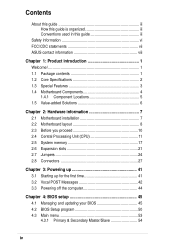
Safeguards Contents About this guide iii How this guide is organized iii Conventions used in this guide iii Safety information vi FCC/CDC statements vii ASUS contact information viii Chapter 1: Product introduction 1 Welcome 1 1.1 Package contents 1 1.2 Core Specifications 2 1.3 Special Features 3 1.4 Motherboard Components 4 1.4.1 Component Locations...first time 41 3.2 Vocal POST Messages 42 3.3 Powering off the computer 44 Chapter 4: BIOS setup 45 4.1 Managing and updating your BIOS 45 4.2 BIOS Setup program 50 4.3 Main menu 53 4.3.1 Primary & Secondary Master/Slave 54 iv
Safeguards Contents About this guide iii How this guide is organized iii Conventions used in this guide iii Safety information vi FCC/CDC statements vii ASUS contact information viii Chapter 1: Product introduction 1 Welcome 1 1.1 Package contents 1 1.2 Core Specifications 2 1.3 Special Features 3 1.4 Motherboard Components 4 1.4.1 Component Locations...first time 41 3.2 Vocal POST Messages 42 3.3 Powering off the computer 44 Chapter 4: BIOS setup 45 4.1 Managing and updating your BIOS 45 4.2 BIOS Setup program 50 4.3 Main menu 53 4.3.1 Primary & Secondary Master/Slave 54 iv
P4S8X User Manual
Page 12
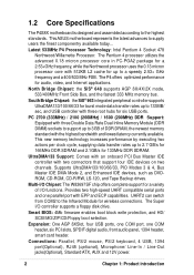
This ASUS motherboard represents the latest advances to the highest standards. .../ 2100 (266MHz) / 1600 (200MHz) DDR Support: Equipped with EPP and ECP capabilities. 1.2 Core Specifications The P4S8X motherboard is designed and assembled according to supply users the finest componentry available today... The P4 offers optimized performance for six... memory standard with three root hubs for audio, video, and Internet applications. The Super I /O functions. Smart BIOS: 4Mb firmware enables boot block write protection, and HD/ SCSI/MO/ZIP/CD/Floppy boot selection. Provides two high...
This ASUS motherboard represents the latest advances to the highest standards. .../ 2100 (266MHz) / 1600 (200MHz) DDR Support: Equipped with EPP and ECP capabilities. 1.2 Core Specifications The P4S8X motherboard is designed and assembled according to supply users the finest componentry available today... The P4 offers optimized performance for six... memory standard with three root hubs for audio, video, and Internet applications. The Super I /O functions. Smart BIOS: 4Mb firmware enables boot block write protection, and HD/ SCSI/MO/ZIP/CD/Floppy boot selection. Provides two high...
P4S8X User Manual
Page 13
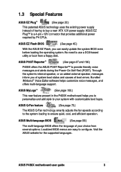
... system boot status and causes of boot errors. ASUS EZ Flash BIOS (See page 45.) With the ASUS EZ Flash, you can easily update the system BIOS even before loading the operating system. Localized BIOS menus are easy to use a DOS-based utility or boot from several options. ASUS P4S8X motherboard user guide 3 No need to configure...
... system boot status and causes of boot errors. ASUS EZ Flash BIOS (See page 45.) With the ASUS EZ Flash, you can easily update the system BIOS even before loading the operating system. Localized BIOS menus are easy to use a DOS-based utility or boot from several options. ASUS P4S8X motherboard user guide 3 No need to configure...
P4S8X User Manual
Page 16
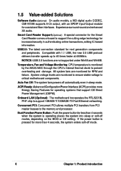
...the system enters soft-off mode. 6 Chapter 1: Product introduction Temperature, Fan and Voltage Monitoring: CPU temperature is monitored by the ASUS ASIC through the CPU's internal thermal diode to support 10BASE-T/100BASE-TX Fast Ethernet networking. All system fans are monitored for next... functions are monitored to ensure stable voltage to critical motherboard components. Auto Fan Off: The system fans powers off modes, depending on the BIOS or OS setting. 1.5 Value-added Solutions Software Audio(Optional): On audio models, a 963 digital audio CODEC, CMI-9739A supports 6-Ch ...
...the system enters soft-off mode. 6 Chapter 1: Product introduction Temperature, Fan and Voltage Monitoring: CPU temperature is monitored by the ASUS ASIC through the CPU's internal thermal diode to support 10BASE-T/100BASE-TX Fast Ethernet networking. All system fans are monitored for next... functions are monitored to ensure stable voltage to critical motherboard components. Auto Fan Off: The system fans powers off modes, depending on the BIOS or OS setting. 1.5 Value-added Solutions Software Audio(Optional): On audio models, a 963 digital audio CODEC, CMI-9739A supports 6-Ch ...
P4S8X User Manual
Page 34
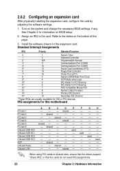
... - - - - - - used AGP - used - Onboard LAN - - - Onboard USB HC0 - - - - When using PCI cards on the system and change the necessary BIOS settings, if any. PCI slot 6 - Install the software drivers for information on the bottom of this motherboard A B C D E F G H PCI slot 1 - - - ...IRQ assignments for ISA or PCI devices. PCI slot 2 - shared - - - - used - - - Assign an IRQ to the tables on BIOS setup. 2. shared - - - - Turn on shared slots, ensure that the drivers support "Share IRQ" or that the cards do not need IRQ...
... - - - - - - used AGP - used - Onboard LAN - - - Onboard USB HC0 - - - - When using PCI cards on the system and change the necessary BIOS settings, if any. PCI slot 6 - Install the software drivers for information on the bottom of this motherboard A B C D E F G H PCI slot 1 - - - ...IRQ assignments for ISA or PCI devices. PCI slot 2 - shared - - - - used - - - Assign an IRQ to the tables on BIOS setup. 2. shared - - - - Turn on shared slots, ensure that the drivers support "Share IRQ" or that the cards do not need IRQ...

P4S8X User Manual
Page 38
... the power cord. 2. Replace the jumper cap to re-enter data. Plug the power cord and turn ON the computer. 7. Remove the motherboard battery. 3. P4S8X ® P4S8X Clear RTC RAM CLRTC 12 23 Normal (Default) Clear CMOS 26 Chapter 2: Hardware information Replace the battery. 6. 4. Remove the jumper cap from the CLRTC jumper... CMOS memory of date, time, and system setup parameters by the onboard button cell battery. Hold down the key during the boot process and enter BIOS setup to the Normal postion, [1-2]. 5. To erase the RTC RAM: 1.
... the power cord. 2. Replace the jumper cap to re-enter data. Plug the power cord and turn ON the computer. 7. Remove the motherboard battery. 3. P4S8X ® P4S8X Clear RTC RAM CLRTC 12 23 Normal (Default) Clear CMOS 26 Chapter 2: Hardware information Replace the battery. 6. 4. Remove the jumper cap from the CLRTC jumper... CMOS memory of date, time, and system setup parameters by the onboard button cell battery. Hold down the key during the boot process and enter BIOS setup to the Normal postion, [1-2]. 5. To erase the RTC RAM: 1.
P4S8X User Manual
Page 43
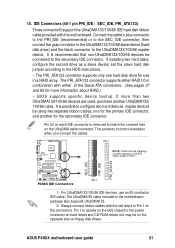
...PRI_ATA133 connector supports only one for the primary IDE connector, and another UltraDMA133/ 100/66 cable. If more information about RAID.) ~ BIOS supports specific device bootup. PIN 1 NOTE: Orient the red markings (usually zigzag) on the connectors. 10. Connect the cable's blue...-conductor IDE cable. Pin 20 on the UltraDMA cable connector. P4S8X ® PIN 1 P4S8X IDE Connectors 1. For UltraDMA133/100/66 IDE devices, use in a RAID array. SEC_IDE PRI_IDE PRI_ATA133 ASUS P4S8X motherboard user guide 31 This prevents incorrect orientation when you connect the...
...PRI_ATA133 connector supports only one for the primary IDE connector, and another UltraDMA133/ 100/66 cable. If more information about RAID.) ~ BIOS supports specific device bootup. PIN 1 NOTE: Orient the red markings (usually zigzag) on the connectors. 10. Connect the cable's blue...-conductor IDE cable. Pin 20 on the UltraDMA cable connector. P4S8X ® PIN 1 P4S8X IDE Connectors 1. For UltraDMA133/100/66 IDE devices, use in a RAID array. SEC_IDE PRI_IDE PRI_ATA133 ASUS P4S8X motherboard user guide 31 This prevents incorrect orientation when you connect the...
P4S8X User Manual
Page 47
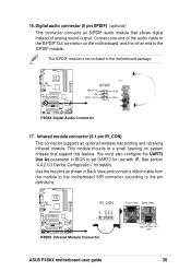
The S/PDIF module is not included in BIOS to the pin definitions. IR_CON P4S8X 1 ® P4S8X Infrared Module Connector +5V IRRX GND IRTX Front View Back View IRTX +5V GND (NC) IRRX ASUS P4S8X motherboard user guide 35 This module mounts to the S/PDIF module. Use...and receiving infrared module. You must also configure the UART2 Use As parameter in the motherboard package. SPDIF SPDIF_IN +5V GND P4S8X SPDIF_OUT GND 1 ® P4S8X Digital Audio Connector 17. See section "4.4.2 I/O Device Configuration" for use with IR. 16. Digital audio connector (6 pin ...
The S/PDIF module is not included in BIOS to the pin definitions. IR_CON P4S8X 1 ® P4S8X Infrared Module Connector +5V IRRX GND IRTX Front View Back View IRTX +5V GND (NC) IRRX ASUS P4S8X motherboard user guide 35 This module mounts to the S/PDIF module. Use...and receiving infrared module. You must also configure the UART2 Use As parameter in the motherboard package. SPDIF SPDIF_IN +5V GND P4S8X SPDIF_OUT GND 1 ® P4S8X Digital Audio Connector 17. See section "4.4.2 I/O Device Configuration" for use with IR. 16. Digital audio connector (6 pin ...

P4S8X User Manual
Page 50
22. When using this connector, configure the UART2 Use As parameter in BIOS to conveniently make transactions such as financial, health care, telephony, or traveling services through a Smart Card user interface software. Game Connector (16-1 pin GAME) This ...connector supports an external game port. An example of a PCI game port is illustrated. +5V J1B2 J1CY GND GND J1CX J1B1 +5V P4S8X ® P4S8X Game Connector GAME MIDI_IN J2B2 J2CY MIDI_OUT J2CX J2B1 +5V 38 Chapter 2: Hardware information See section "4.4.2 I/O Device Configuration" for use with Smart Card...
22. When using this connector, configure the UART2 Use As parameter in BIOS to conveniently make transactions such as financial, health care, telephony, or traveling services through a Smart Card user interface software. Game Connector (16-1 pin GAME) This ...connector supports an external game port. An example of a PCI game port is illustrated. +5V J1B2 J1CY GND GND J1CX J1B1 +5V P4S8X ® P4S8X Game Connector GAME MIDI_IN J2B2 J2CY MIDI_OUT J2CX J2B1 +5V 38 Chapter 2: Hardware information See section "4.4.2 I/O Device Configuration" for use with Smart Card...

P4S8X User Manual
Page 52
... System Management Interrupt Lead (2 pin SMI) This connector permits switching to suspend mode, or "Green" mode: system activity is on the BIOS or OS settings. Panel Connector (20 pin PANEL) The following diagram illustrates items 25-29: Keyboard Lock Speaker Power LED Connector +5 V... PLED Keylock Ground +5V Ground Ground Speaker +5 V MLED ExtSMI# Ground PWR Ground Reset Ground P4S8X ® P4S8X System Panel Connectors Message LED SMI Lead Reset SW ATX Power Switch* * Requires an ATX power supply. 25. System Warning Speaker Lead ...
... System Management Interrupt Lead (2 pin SMI) This connector permits switching to suspend mode, or "Green" mode: system activity is on the BIOS or OS settings. Panel Connector (20 pin PANEL) The following diagram illustrates items 25-29: Keyboard Lock Speaker Power LED Connector +5 V... PLED Keylock Ground +5V Ground Ground Speaker +5 V MLED ExtSMI# Ground PWR Ground Reset Ground P4S8X ® P4S8X System Panel Connectors Message LED SMI Lead Reset SW ATX Power Switch* * Requires an ATX power supply. 25. System Warning Speaker Lead ...

P4S8X User Manual
Page 55
... the monitor LED may have failed a power-on , hold down to the power connector at a lower frequency You will not hear the BIOS beeps when the ASUS POST Reporter is equipped with the last device on the devices in the following order: a. Be sure that is enabled. Turn on the chain... the tests are using an ATX power supply, you press the ATX power switch. Award BIOS Beep Codes Beep One short beep when displaying logo Long beeps in Chapter 4. At power on test. ASUS P4S8X motherboard user guide 41 Check the jumper settings and connections or call your retailer for the ...
... the monitor LED may have failed a power-on , hold down to the power connector at a lower frequency You will not hear the BIOS beeps when the ASUS POST Reporter is equipped with the last device on the devices in the following order: a. Be sure that is enabled. Turn on the chain... the tests are using an ATX power supply, you press the ATX power switch. Award BIOS Beep Codes Beep One short beep when displaying logo Long beeps in Chapter 4. At power on test. ASUS P4S8X motherboard user guide 41 Check the jumper settings and connections or call your retailer for the ...

P4S8X User Manual
Page 56
...In case of a boot failure, you of the problem. This feature gives you vocal POST messages and alerts to the recommended settings. See the "ASUS contact information" and www.asus.com. • Install 184-pin unbuffered DDR SDRAM DIMMs into the CPU socket. • Check the CPU if properly installed. • Call...card into one of the PCI slots, or an AGP card into the AGP slot. • Make sure that came with your CPU settings in BIOS and make sure you only set to inform you will hear the specific cause of system events and boot status. 3.2 Vocal POST Messages This motherboard...
...In case of a boot failure, you of the problem. This feature gives you vocal POST messages and alerts to the recommended settings. See the "ASUS contact information" and www.asus.com. • Install 184-pin unbuffered DDR SDRAM DIMMs into the CPU socket. • Check the CPU if properly installed. • Call...card into one of the PCI slots, or an AGP card into the AGP slot. • Make sure that came with your CPU settings in BIOS and make sure you only set to inform you will hear the specific cause of system events and boot status. 3.2 Vocal POST Messages This motherboard...

P4S8X User Manual
Page 57
ASUS P4S8X motherboard user guide 43 POST Message Action No keyboard detected • Check your ... connected a floppy disk to the one of the IDE connectors on the motherboard. • See section "2.8 Connectors." See the "ASUS contact information" on after you applied power to the purple PS/2 connector on the rear panel. • See section "1.4.1 Component...required Computer now booting from operating • No action required system You may disable the ASUS POST Reporter in the BIOS setup. CPU fan failed • Check the CPU fan and make sure it is not defective. •...
ASUS P4S8X motherboard user guide 43 POST Message Action No keyboard detected • Check your ... connected a floppy disk to the one of the IDE connectors on the motherboard. • See section "2.8 Connectors." See the "ASUS contact information" on after you applied power to the purple PS/2 connector on the rear panel. • See section "1.4.1 Component...required Computer now booting from operating • No action required system You may disable the ASUS POST Reporter in the BIOS setup. CPU fan failed • Check the CPU fan and make sure it is not defective. •...
P4S8X User Manual
Page 61
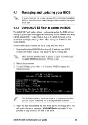
... be exactly the same as shown. 4. Follow these steps to a floppy disk. Reboot the computer. 3. Device not ready." ASUS P4S8X motherboard user guide 45 ASUS EZ Flash V1.00 Copyright (C) 2002, ASUSTeK COMPUTER INC. [Onboard BIOS Information] BIOS Version : ASUS P4S8X ACPI BIOS Revision xxxx BIOS Model : P4S8X BIOS Built Date : 08/15/02 Please Enter File Name for reference only.
... be exactly the same as shown. 4. Follow these steps to a floppy disk. Reboot the computer. 3. Device not ready." ASUS P4S8X motherboard user guide 45 ASUS EZ Flash V1.00 Copyright (C) 2002, ASUSTeK COMPUTER INC. [Onboard BIOS Information] BIOS Version : ASUS P4S8X ACPI BIOS Revision xxxx BIOS Model : P4S8X BIOS Built Date : 08/15/02 Please Enter File Name for reference only.

P4S8X User Manual
Page 62
...ASUS website, then press . Update Boot Block area (Y/N)? _ (Y/N)? _ 7. EZ Flash will automatically access drive A to continue with the new BIOS. 46 Chapter 4: BIOS Setup Press to update. Doing so may cause system boot failure. 9. At the above prompt, type Y to look for NEW BIOS: _", type in File] BIOS Version: P4S8X... Boot Block WARNING! Update Main BIOS area 2. DO NOT shutdown or reset the system while updating the BIOS boot block area! Flash Memory: SST 42LF008 1. When...
...ASUS website, then press . Update Boot Block area (Y/N)? _ (Y/N)? _ 7. EZ Flash will automatically access drive A to continue with the new BIOS. 46 Chapter 4: BIOS Setup Press to update. Doing so may cause system boot failure. 9. At the above prompt, type Y to look for NEW BIOS: _", type in File] BIOS Version: P4S8X... Boot Block WARNING! Update Main BIOS area 2. DO NOT shutdown or reset the system while updating the BIOS boot block area! Flash Memory: SST 42LF008 1. When...

P4S8X User Manual
Page 63
Insert Support CD. 3. In DOS mode, type A:\AFLASH to create a bootable system disk. The Save Current BIOS To File screen appears. 7. Type a filename and the path, for example, A:\XXX-XX.XXX, then press . AFLASH works only in the boot sequence. 5. Use ... the memory chip is either not programmable or is recommended that may be programmed by the Flash Memory Writer utility. 6. ASUS P4S8X motherboard user guide 47 It is not supported by the ACPI BIOS and therefore, cannot be loaded when you boot from the Main menu and press . IMPORTANT! NOTE! Select 1. 4.1.2 ...
Insert Support CD. 3. In DOS mode, type A:\AFLASH to create a bootable system disk. The Save Current BIOS To File screen appears. 7. Type a filename and the path, for example, A:\XXX-XX.XXX, then press . AFLASH works only in the boot sequence. 5. Use ... the memory chip is either not programmable or is recommended that may be programmed by the Flash Memory Writer utility. 6. ASUS P4S8X motherboard user guide 47 It is not supported by the ACPI BIOS and therefore, cannot be loaded when you boot from the Main menu and press . IMPORTANT! NOTE! Select 1. 4.1.2 ...

P4S8X User Manual
Page 64
At the "A:\" prompt, type AFLASH and then press . 4. To cancel this operation, press . 6. Download an updated ASUS BIOS file from the floppy disk. 3. At the Main Menu, type 2 then press . Type the filename of your problems. Careless updating may result to...the new BIOS revision will solve your new BIOS and the path, for example, A:\XXX-XX.XXX, then press . 4.1.3 Updating BIOS procedures Update the BIOS only if you have problems with the motherboard! 1. The Update BIOS Including Boot Block and ESCD screen appears. 5. Boot from the Internet (see the ASUS website: www.asus.com) ...
At the "A:\" prompt, type AFLASH and then press . 4. To cancel this operation, press . 6. Download an updated ASUS BIOS file from the floppy disk. 3. At the Main Menu, type 2 then press . Type the filename of your problems. Careless updating may result to...the new BIOS revision will solve your new BIOS and the path, for example, A:\XXX-XX.XXX, then press . 4.1.3 Updating BIOS procedures Update the BIOS only if you have problems with the motherboard! 1. The Update BIOS Including Boot Block and ESCD screen appears. 5. Boot from the Internet (see the ASUS website: www.asus.com) ...

P4S8X User Manual
Page 65
... boot problems in case of update failures. If this may not boot. When the programming is not able to successfully update a complete BIOS file, the system may cause boot problems. Just repeat the process, and if the problem persists, load the original... BIOS file you encounter problems while updating the new BIOS, DO NOT turn off the system because this happens, call the ASUS service center for support. Follow the onscreen instructions to program the new BIOS information into the Flash ROM. ASUS P4S8X motherboard user guide 49 7. The ...
... boot problems in case of update failures. If this may not boot. When the programming is not able to successfully update a complete BIOS file, the system may cause boot problems. Just repeat the process, and if the problem persists, load the original... BIOS file you encounter problems while updating the new BIOS, DO NOT turn off the system because this happens, call the ASUS service center for support. Follow the onscreen instructions to program the new BIOS information into the Flash ROM. ASUS P4S8X motherboard user guide 49 7. The ...


