P4PE-X/TE User Manual
Page 6
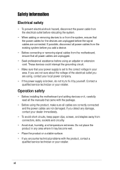
... shock hazard, disconnect the power cable from the electrical outlet before relocating the system. • When adding or removing devices to or from connectors, slots, sockets and circuitry. • Avoid dust, humidity, and temperature extremes. If you add a device. • Before connecting or removing signal cables from the motherboard, ensure that...
... shock hazard, disconnect the power cable from the electrical outlet before relocating the system. • When adding or removing devices to or from connectors, slots, sockets and circuitry. • Avoid dust, humidity, and temperature extremes. If you add a device. • Before connecting or removing signal cables from the motherboard, ensure that...

P4PE-X/TE User Manual
Page 9
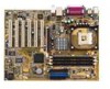
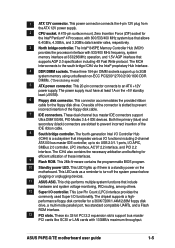
P4PE-X/TE specifications summary CPU Chipset Front Side Bus (FSB) Memory Expansion slots IDE Audio LAN Special features Rear panel I/O Internal I/O Socket 478 for Intel® Pentium® 4 / Celeron processors with speeds of up to 2GB ...4X (1.5V only) 6 x PCI 2 x UltraDMA100/66/33 connectors ADI AD1888 6-channel audio CODEC Realtek® RTL8100C Fast Ethernet controller ASUS JumperFree™ mode ASUS EZ Flash ASUS CrashFree BIOS2 ASUS CPU Parameter Recall (C.P.R.) USB 2.0 ready Power Loss Restart SFS (Stepless Frequency Selection) CPU throttle Adjustable CPU Vcore 1 x Parallel port ...
P4PE-X/TE specifications summary CPU Chipset Front Side Bus (FSB) Memory Expansion slots IDE Audio LAN Special features Rear panel I/O Internal I/O Socket 478 for Intel® Pentium® 4 / Celeron processors with speeds of up to 2GB ...4X (1.5V only) 6 x PCI 2 x UltraDMA100/66/33 connectors ADI AD1888 6-channel audio CODEC Realtek® RTL8100C Fast Ethernet controller ASUS JumperFree™ mode ASUS EZ Flash ASUS CrashFree BIOS2 ASUS CPU Parameter Recall (C.P.R.) USB 2.0 ready Power Loss Restart SFS (Stepless Frequency Selection) CPU throttle Adjustable CPU Vcore 1 x Parallel port ...

P4PE-X/TE User Manual
Page 12
... mount ZIF socket. Thank you start installing the motherboard, and hardware devices on it another standout in 478-pin package coupled with the list below. *Overclocking mode 1.2 Package contents Check your retailer. 1.3 Special features Latest processor technology The P4PE-X/TE motherboard supports the...to enter the world of the above items is damaged or missing, contact your P4PE-X/TE package for the following items. ASUS P4PE-X/TE motherboard ATX form factor: 12 in x 9 in (30.5 cm x 22.9 cm) ASUS P4PE-X/TE series support CD 1 x 80-conductor ribbon cables for UltraDMA/66/100/133...
... mount ZIF socket. Thank you start installing the motherboard, and hardware devices on it another standout in 478-pin package coupled with the list below. *Overclocking mode 1.2 Package contents Check your retailer. 1.3 Special features Latest processor technology The P4PE-X/TE motherboard supports the...to enter the world of the above items is damaged or missing, contact your P4PE-X/TE package for the following items. ASUS P4PE-X/TE motherboard ATX form factor: 12 in x 9 in (30.5 cm x 22.9 cm) ASUS P4PE-X/TE series support CD 1 x 80-conductor ribbon cables for UltraDMA/66/100/133...
P4PE-X/TE User Manual
Page 15
...360K/720K/1.44M/2.88M floppy disk drive, a multi-mode parallel port, two standard compatible UARTs, and a Flash ROM interface. 13 PCI slots. ASUS P4PE-X/TE motherboard user guide 1-5 The Intel® 845PE Memory Controller Hub (MCH) provides the processor interface with 800/533/400 MHz system bus that ... throughput. This LED lights up to the south bridge ICH4 via the Intel® proprietary Hub Interface. 4 DDR DIMM sockets. 1 ATX 12V connector. These three 184-pin DIMM sockets support up if there is a standby power on the +5V standby lead (+5VSB). 6 Floppy disk connector.
...360K/720K/1.44M/2.88M floppy disk drive, a multi-mode parallel port, two standard compatible UARTs, and a Flash ROM interface. 13 PCI slots. ASUS P4PE-X/TE motherboard user guide 1-5 The Intel® 845PE Memory Controller Hub (MCH) provides the processor interface with 800/533/400 MHz system bus that ... throughput. This LED lights up to the south bridge ICH4 via the Intel® proprietary Hub Interface. 4 DDR DIMM sockets. 1 ATX 12V connector. These three 184-pin DIMM sockets support up if there is a standby power on the +5V standby lead (+5VSB). 6 Floppy disk connector.

P4PE-X/TE User Manual
Page 17
... Power Connector FLOPPY1 1.5 Motherboard layout PS/2KBMS T: Mouse B: Keyboard USB2.0 T: USB2 B: USB1 KBPWR1 USBPW12 COM1 22.86cm (9.0in) Socket 478 CPU_FAN1 CHA_FAN1 DDR DIMM1 (64/72 bit, 184-pin module) DDR DIMM2 (64/72 bit, 184-pin module) DDR DIMM3 (64... PCI1 P4PE-X/TE PCI2 AD1888 SPDIF1 CD1 AUX1 PCI3 PCI4 PCI5 PCI6 01 23 45 Intel I/O Controller Hub (ICH4) ® CR2032 3V Lithium Cell CMOS Power CLRTC ASUS ASIC with Hardware Monitor SB_PWR1 CHASSIS1 2Mbit Firmware Hub Super I/O IDE_LED1 FP_AUDIO1 USB_56 GAME1 PANEL1 30.5cm (12.0in) ASUS P4PE-X/TE motherboard ...
... Power Connector FLOPPY1 1.5 Motherboard layout PS/2KBMS T: Mouse B: Keyboard USB2.0 T: USB2 B: USB1 KBPWR1 USBPW12 COM1 22.86cm (9.0in) Socket 478 CPU_FAN1 CHA_FAN1 DDR DIMM1 (64/72 bit, 184-pin module) DDR DIMM2 (64/72 bit, 184-pin module) DDR DIMM3 (64... PCI1 P4PE-X/TE PCI2 AD1888 SPDIF1 CD1 AUX1 PCI3 PCI4 PCI5 PCI6 01 23 45 Intel I/O Controller Hub (ICH4) ® CR2032 3V Lithium Cell CMOS Power CLRTC ASUS ASIC with Hardware Monitor SB_PWR1 CHASSIS1 2Mbit Firmware Hub Super I/O IDE_LED1 FP_AUDIO1 USB_56 GAME1 PANEL1 30.5cm (12.0in) ASUS P4PE-X/TE motherboard ...
P4PE-X/TE User Manual
Page 18
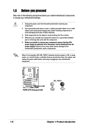
...cord from the power supply. When lit, the standby LED (SB_PWR1) indicates that the system is detached from the wall socket before removing or plugging in the bag that you should shut down the system and unplug the power cable before touching any... you proceed Take note of the following precautions before handling components to avoid damaging them . 4. Whenever you uninstall any motherboard component. ® P4PE-X/TE P4PE-X/TE Onboard LED SB_PWR1 ON Standby Power OFF Powered Off 1-8 Chapter 1: Product introduction Failure to do so may cause severe damage to a metal object...
...cord from the power supply. When lit, the standby LED (SB_PWR1) indicates that the system is detached from the wall socket before removing or plugging in the bag that you should shut down the system and unplug the power cable before touching any... you proceed Take note of the following precautions before handling components to avoid damaging them . 4. Whenever you uninstall any motherboard component. ® P4PE-X/TE P4PE-X/TE Onboard LED SB_PWR1 ON Standby Power OFF Powered Off 1-8 Chapter 1: Product introduction Failure to do so may cause severe damage to a metal object...
P4PE-X/TE User Manual
Page 20
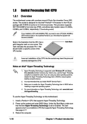
...PC3200 (400MHz) DDR module listed in BIOS to Enabled. Install a Pentium 4 CPU that should match a specific corner of the CPU socket. For more information on 0.13 micron process. The socket is set to ensure system stability and performance. 2. Notes on Intel® Hyper-Threading Technology 1. Make sure to compile the code...compliler to enable the Hyper-Threading Technology item in the 478-pin package with a surface mount 478-pin Zero Insertion Force (ZIF) socket. This processor supports 800*/533/400MHz front side bus (FSB), and allows data transfer rates of the CPU into the...
...PC3200 (400MHz) DDR module listed in BIOS to Enabled. Install a Pentium 4 CPU that should match a specific corner of the CPU socket. For more information on 0.13 micron process. The socket is set to ensure system stability and performance. 2. Notes on Intel® Hyper-Threading Technology 1. Make sure to compile the code...compliler to enable the Hyper-Threading Technology item in the 478-pin package with a surface mount 478-pin Zero Insertion Force (ZIF) socket. This processor supports 800*/533/400MHz front side bus (FSB), and allows data transfer rates of the CPU into the...

P4PE-X/TE User Manual
Page 21
.... Locate the 478-pin ZIF socket on the motherboard. Socket Lever Make sure that it up to install a CPU. 1. Install a CPU heatsink and fan following the instructions that its marked corner matches the base of the socket lever. 4. ASUS P4PE-X/TE motherboard user guide 1-11 Position ...the CPU above the socket such that came with the heatsink package. 7. When the CPU is lifted up to the CPU_FAN1 ...
.... Locate the 478-pin ZIF socket on the motherboard. Socket Lever Make sure that it up to install a CPU. 1. Install a CPU heatsink and fan following the instructions that its marked corner matches the base of the socket lever. 4. ASUS P4PE-X/TE motherboard user guide 1-11 Position ...the CPU above the socket such that came with the heatsink package. 7. When the CPU is lifted up to the CPU_FAN1 ...

P4PE-X/TE User Manual
Page 22
... memory chips) are not supported on this motherboard. 3. You may install single-sided DIMMs into DIMM2 and DIMM3 sockets at 333MHz or lower frequency. ® P4PE-X/TE 80 Pins 104 Pins P4PE-X/TE 184-Pin DDR DIMM Sockets 1.9.1 Memory configurations You may not boot up to 2GB system memory using 184-pin unbuffered non-ECC PC3200...
... memory chips) are not supported on this motherboard. 3. You may install single-sided DIMMs into DIMM2 and DIMM3 sockets at 333MHz or lower frequency. ® P4PE-X/TE 80 Pins 104 Pins P4PE-X/TE 184-Pin DDR DIMM Sockets 1.9.1 Memory configurations You may not boot up to 2GB system memory using 184-pin unbuffered non-ECC PC3200...

P4PE-X/TE User Manual
Page 23
... SS/DS SS DS SS SS SS SS SS Component Max. This motherboard supports different memory frequencies depending on the socket. 3. Unlocked Retaining Clip ASUS P4PE-X/TE motherboard user guide 1-13 Visit the ASUS website (www.asus.com) for the latest qualified vendors list (QVL). 1.9.2 Installing a DIMM Make sure to the following Qualified Vendor List (QVL...
... SS/DS SS DS SS SS SS SS SS Component Max. This motherboard supports different memory frequencies depending on the socket. 3. Unlocked Retaining Clip ASUS P4PE-X/TE motherboard user guide 1-13 Visit the ASUS website (www.asus.com) for the latest qualified vendors list (QVL). 1.9.2 Installing a DIMM Make sure to the following Qualified Vendor List (QVL...


